


 2025-12-11
 BEST
BEST
Designing and ordering a flexible printed circuit board starts with choosing the right flex pcb type for your project. You need to follow design rules, prepare accurate files, and select a manufacturer who understands flexible printed circuit boards. To achieve reliable performance and cost-effective results, pay attention to material selection, flex circuit board layout, and bending requirements. You may face challenges with pcb assembly or flex durability. If you want a quote or need advice, send an inquiry to your chosen supplier.
- Select your flex type and structure
- Follow design guidelines for flexible circuits
- Prepare files for manufacturing
- Submit your order and request a price quote
Key Takeaways
- Choose the right type of flex PCB based on your project's needs. Consider factors like complexity, space, and mechanical stress.
- Follow design guidelines closely to ensure reliability. Pay attention to material selection, bending requirements, and trace layout.
- Prepare accurate manufacturing files in the correct formats. Double-check for completeness to avoid production delays.
- Communicate clearly with your manufacturer. Provide detailed specifications and ask for feedback to ensure your design meets expectations.
- Request a price quote early in the process. This helps you understand costs and make informed decisions about your flex PCB project.
Flexible Printed Circuit Boards Overview
What Are Flexible Printed Circuit Boards
You work with flexible printed circuit boards when you need a solution that bends, twists, or folds to fit your design. These boards use thin, flexible materials instead of rigid substrates. You can create circuits that move or fit into tight spaces. Flexible printed circuit boards stand out because they handle more complex manufacturing steps and use a wider range of materials than rigid alternatives.
| Feature | Flexible PCBs | Rigid PCBs |
|---|---|---|
| Manufacturing Complexity | More complex with 17 steps | Less complex with 8 steps |
| Material Usage | More materials involved | Fewer materials involved |
| Cost | Generally more costly | Generally less costly |
| Layer Configuration | Can be multi-layer | Typically single or double-sided |
| Thermal Resistance | Better heat resistance | Less heat resistance |
You see flexible printed circuit boards in many types of electronics. You choose a flex pcb when you need a lightweight, durable, and adaptable circuit.
Key Benefits and Drawbacks
You gain several advantages of flexible pcb when you select this technology. Flexible printed circuit boards offer flexibility for tight spaces, better shock absorption, and weight reduction. You also benefit from cost-effective production and enhanced thermal management. However, you must consider disadvantages of flexible pcb, such as lower mechanical strength, limited temperature resistance, and assembly challenges.
| Type of PCB | Advantages | Disadvantages |
|---|---|---|
| Flexible | 1. Flexibility for tight spaces | |
| 2. Better shock absorption | ||
| 3. Weight reduction | ||
| 4. Cost-effective | ||
| 5. Enhanced thermal management | 1. Lower mechanical strength | |
| 2. Limited temperature resistance | ||
| 3. Assembly challenges | ||
| Rigid | 1. Rigid structure for stability | |
| 2. High temperature resistance | ||
| 3. Mechanical strength | ||
| 4. Surface mounting compatibility | ||
| 5. Better electrical performance | 1. Limited flexibility | |
| 2. Risk of fracture |
You should weigh these types and their features before starting your design.
Main Applications
You find applications of flexible pcb in many sectors. The most common flex pcb use cases include consumer electronics, automotive, medical, and industrial types.
| Sector | Applications |
|---|---|
| Consumer Electronics | Used in smartwatches, fitness trackers, and other wearable tech for flexibility and durability. |
| Automotive Industry | Ensures efficient communication between sensors and control units in cars. |
| Medical and Healthcare | Compact and reliable connections in small devices like MRI and CT scanners. |
| Industrial Applications | Provides flexibility and durability in robotic arms and automated systems. |
You can explore these applications to see how flexible printed circuit boards improve reliability and performance. If you want to learn more about types or request a quote, you can send an inquiry to a supplier for guidance.
Flex PCB Types and Structure

Single-Sided Flex PCB
You often start with a single-sided flex pcb when your design needs basic flexibility and simple circuitry. This type uses one conductive layer on a flexible substrate. You find it ideal for compact devices, such as cameras or printers. You can bend and fold the board without risking electrical failure. You achieve cost savings and reliability for straightforward applications.
Double-Sided Flex PCB
You choose a double-sided flex pcb for more complex circuits. This type features two conductive layers separated by an insulating substrate. You route signals on both sides, which increases design options. You use plated through-holes to connect the layers. You see double-sided flex pcb in medical devices and automotive sensors where space and performance matter.
Multi-Layer Flex PCB
You select a multi-layered flex pcb when your project demands advanced functionality. This structure stacks three or more conductive layers with insulating substrates. You gain improved signal integrity and higher circuit density. You use this type in aerospace and industrial equipment. You achieve robust performance in harsh environments.
Rigid-Flex PCB
You combine rigid and flexible sections in a rigid-flex pcb. You use rigid areas for mounting components and flexible sections for bending. You reduce connectors and improve reliability. You find rigid-flex pcb in smartphones and military electronics. You simplify assembly and enhance durability.
Materials and Layer Stack
You must choose materials carefully for flex pcb construction. The table below shows common materials and their impact:
| Material Type | Description | Impact on Performance |
|---|---|---|
| Core Materials | Provide strength and stability; commonly used materials include FR4, polyimide, and ceramic-filled laminates. | Essential for durability and reliability of PCBs. |
| Dielectric Substrates | Include prepreg materials that hold layers together and affect electrical properties. | Critical for the electrical performance of the PCB. |
| Surface Finishes | Options like HASL, ENIG, and immersion tin prepare PCBs for soldering. | Influence solderability and overall functionality. |
You improve reliability and electrical performance by selecting the right stack and finish. You can request a quote to compare options for your application.
Stiffeners and Support
You add stiffeners and support materials to strengthen flex pcb designs. These elements play a vital role in reliability. The table below highlights their benefits:
| Role of Stiffeners and Support Materials | Description |
|---|---|
| Structural Integrity | They provide essential support to maintain the shape of the PCB under stress. |
| Mechanical Stress Reduction | They help in minimizing the mechanical stress experienced during operation. |
| Longevity and Functionality | By maintaining performance under various conditions, they enhance the lifespan of electronic devices. |
Tip: You should discuss stiffener options with your supplier to ensure your flex pcb meets your durability requirements.
You explore different types of flexible circuit boards to match your project needs. You can send an inquiry to get expert advice or a price quote for your design.
Flex PCB Design Guidelines
Material Selection
You must select materials carefully during flex pcb design. The right choice impacts reliability, flexibility, and cost. When you evaluate materials for flexible printed circuit boards, focus on these factors:
- Dielectric constant (Dk)
- Dimensional stability
- Thermal expansion
- Glass transition temperature (Tg)
- Fire retardancy
- Loss factor
- Thermal conductivity
You improve performance and reduce failures by considering these properties. You can always request a quote from your supplier to compare material options for your flex pcb.
Bending and Flexibility
You design for bending by understanding how your flex pcb will move. You should avoid sharp bends and keep the bend radius as large as possible. Place traces perpendicular to the bend line. This approach prevents cracks and extends the life of your flexible circuit. You can ask your manufacturer for recommendations on minimum bend radius for your application.
Trace and Pad Design
You must follow best practices for trace and pad layout in flex pcb design. Use rounded traces instead of sharp angles. Keep trace widths consistent. Space pads evenly to avoid stress points. You should avoid placing vias in bend areas. These steps help you maintain electrical integrity and mechanical strength.
Polygon and Corner Layout
You improve flex pcb reliability by smoothing corners and polygons. Use teardrop shapes at trace-to-pad connections. Avoid acute angles. Rounded corners distribute stress and prevent tearing. You should review your design for any sharp features before submitting files for production.
EMI and Signal Integrity
You must address electromagnetic interference and signal quality in flex pcb design. The table below shows effective techniques:
| Technique | Description |
|---|---|
| Controlled Impedance Routing | Adjust trace width, thickness, and distance to ground plane to match trace and component impedance, ensuring signal clarity. |
| Microstrip and Stripline | These configurations help maintain signal quality by reducing loss and distortion, thus minimizing EMI. |
| Shielding | Implementing shielding, along with proper grounding and strategic component placement, effectively combats EMI. |
You can discuss these options with your supplier to ensure your flexible pcb meets performance requirements.
Common Design Challenges
You may face several challenges during flex pcb design. The table below highlights the most common issues:
| Design Challenge | Description |
|---|---|
| Signal Integrity Issues | Affects the performance and reliability of the PCB. |
| Manufacturing Complexities | Challenges related to the production process of flexible PCBs. |
| High-Density Interconnects (HDI) | Essential for modern designs to accommodate compact and efficient layouts. |
| RF and High-Speed Design | Critical for ensuring designs can handle high frequencies effectively. |
You can overcome these challenges by working closely with your manufacturer. If you need help, send an inquiry or request a price quote for expert guidance on your flex pcb project.
Design Process for Flex PCBs

You need a clear plan when you start the design process for flex PCBs. Each step builds on the previous one. You ensure reliability and manufacturability by following a structured approach. You can improve your results by working closely with your supplier and requesting feedback or price quotes during each phase.
Define Requirements
You begin by defining the requirements for your flex PCB project. You set the foundation for a successful design by identifying key considerations. The table below outlines the main factors you should address:
| Key Considerations | Description |
|---|---|
| Defining the PCB’s purpose and functionality | Understand what the PCB will do. |
| Selecting appropriate materials | Choose materials for rigid and flexible sections. |
| Determining the layer stack-up and configuration | Plan the arrangement of layers. |
| Establishing manufacturing and assembly constraints | Know the limits of manufacturing processes. |
You clarify your goals and constraints before you move to the next step. You can send an inquiry to your supplier if you need help with material selection or stack-up options.
Choose Flex PCB Type
You select the flex PCB type that matches your requirements. You consider factors such as circuit complexity, mechanical stress, and space limitations. You choose between single-sided, double-sided, multi-layer, or rigid-flex PCB structures. You discuss your application with your manufacturer to confirm the best fit. You can request a price quote to compare options and optimize your design for cost and performance.
Tip: You should always verify that your chosen flex PCB type meets both electrical and mechanical needs. Early consultation with your supplier can prevent costly revisions.
Schematic and Layout
You create a schematic and layout for your flex PCB. You follow a step-by-step process to ensure accuracy and manufacturability:
- Create a schematic diagram of your electronic circuit.
- Define the PCB layout, including component placement.
- Route connections between components, ensuring minimal interference.
- Validate your design against the schematic and manufacturability criteria.
You use specialized design software to streamline this process. You check for errors and confirm that your layout supports the intended flex and bend areas. You can ask your supplier to review your files before finalizing the design.
Apply Design Rules
You apply design rules to maintain reliability and manufacturability. You set trace widths, spacing, and bend radii according to industry standards. You avoid placing vias in bend areas and use rounded corners to reduce stress. You verify that your design meets the electrical and mechanical requirements for flex PCBs. You consult your manufacturer for specific guidelines and recommendations.
Note: You should document all design rules and share them with your supplier. Clear communication helps avoid misunderstandings and production delays.
Prepare Manufacturing Files
You prepare manufacturing files for your flex PCB. You ensure that your files meet the specifications required by your manufacturer. The table below lists the typical formats you need to provide:
| File Format | Specification |
|---|---|
| Gerber data format | RS-274X |
| Drill data format | Excellon |
You double-check your files for completeness and accuracy. You upload them to your supplier’s platform and submit your order. You can request a price quote or ask for a design review before production begins.
Tip: You should keep backup copies of all manufacturing files. Quick access to your files helps resolve issues and speeds up the ordering process.
You follow these steps to achieve a reliable and cost-effective flex PCB design. You improve your results by collaborating with your supplier and requesting expert advice or quotes at each stage.
Ordering Flex PCBs
When you reach the ordering stage for your flex pcb, you need to make several important decisions. Each choice affects the reliability, cost, and performance of your final product. You should approach this process with a clear understanding of your requirements and communicate them directly to your manufacturer.
Manufacturing Options
You can choose from several manufacturing options when ordering a flex pcb. Some suppliers specialize in prototypes, while others focus on high-volume production. You should consider the following:
- Prototype services: Ideal for testing new designs or small runs.
- Standard production: Suitable for established products and larger quantities.
- Quick-turn manufacturing: Delivers flex pcb orders in a short timeframe, often at a premium price.
You should discuss your project timeline and volume needs with your supplier. This helps you select the best manufacturing path for your flexible printed circuit boards.
Layer, Material, and Thickness Selection
Selecting the right number of layers, materials, and thickness for your flex pcb is essential. Your choices impact weight, assembly time, cost, and performance. Consider these factors:
- Weight reduction: Flexible circuits help you minimize the weight of your electronic package.
- Decreased assembly time: Integrating rigid and flexible sections into one flex pcb saves time and increases reliability.
- Purchasing cost: Initial costs may be higher, but you save on connectors and improve reliability.
- Dynamic flexing vs. bend-and-stay: Thin polyimide works best for dynamic applications. Thicker materials suit static bends.
- Heat dissipation: Flexible circuits offer better heat management than traditional boards.
- Bending radius: The number of layers, copper thickness, and application type influence the minimum bend radius.
- Materials: Polyimide and PET are common choices, each with unique properties.
- Design possibilities: Flexible circuits give you more design freedom.
You should review these points with your manufacturer to ensure your flex pcb meets both mechanical and electrical requirements.
Stiffeners and Surface Finish
You can add stiffeners to your flex pcb to increase mechanical strength in specific areas. Stiffeners help support connectors, components, or mounting points. You should specify the location and type of stiffener during the ordering process.
Surface finish selection also plays a key role in solderability and durability. The table below summarizes the most common finishes and their advantages:
| Surface Finish | Advantages |
|---|---|
| HASL | Improves soldering, cost-effective |
| ENIG | Longer lifespan, excellent solderability |
| OSP | Good for soldering, economical |
You should match the surface finish to your assembly process and reliability needs. If you are unsure, your supplier can recommend the best option for your application.
Additional Features
You may want to include additional features in your flex pcb order. These can enhance performance or simplify assembly. Common options include:
- Coverlay for insulation and protection
- Gold fingers for edge connectors
- Selective stiffeners for targeted support
- Custom shapes or cutouts
You should specify these features early in the ordering process. This ensures your flexible pcb meets all functional and mechanical requirements.
File Upload and Order Submission
You need to prepare your design files before submitting your order. Most manufacturers accept Gerber and Excellon formats. You should double-check your files for accuracy and completeness. Many suppliers provide an online portal for file upload and order tracking.
Tip: Upload your files and request a quote directly from the website. This speeds up the review process and helps you get feedback quickly.
If you have questions or need help, you can contact the supplier’s support team. Clear communication at this stage helps prevent delays and ensures your flex pcb matches your expectations.
Cost Factors
Several factors influence the cost of your flex pcb order. You should consider:
- Number of layers and overall size
- Material type and thickness
- Complexity of the design
- Surface finish and stiffener requirements
- Quantity and lead time
You can often reduce costs by optimizing your design for manufacturability and selecting standard materials. Requesting a quote early in the process helps you understand pricing and make informed decisions.
If you are ready to move forward, submit your design files for a quote or reach out to the website for more information. Your supplier can guide you through the ordering process and help you achieve the best results for your flexible printed circuit boards.
Manufacturer Selection
Evaluate Capabilities
You need to choose a manufacturer with proven experience in flex pcb production. Start by reviewing their technical capabilities. Check if they support the layer counts, materials, and advanced features your design requires. Ask about their certifications and quality control processes. Reliable suppliers often provide sample reports, process documentation, and references from similar projects. You can request a small prototype run to evaluate their consistency and attention to detail. This step helps you avoid costly mistakes and ensures your flex pcb meets industry standards.
Communicate Requirements
Clear communication with your manufacturer is essential for accurate production. You should provide detailed specifications and documentation for your flex pcb design. Make sure your files are complete and easy to read. The table below highlights the most important requirements you need to communicate:
| Requirement | Importance |
|---|---|
| Legibility | Ensures that information can be easily read and understood during production and testing. |
| Durability | Labels must withstand high temperatures and harsh chemicals to remain intact throughout use. |
| Compliance with Regulations | Adhering to standards like RoHS and WEEE is crucial for legal production and marketability. |
| Scannability | Information must be easily scannable, even at small sizes, to facilitate tracking and logistics. |
Tip: You can improve results by sharing your design intent and asking for feedback. If you have questions, send an inquiry or request a quote to clarify details before production begins.
Production and Delivery Expectations
You should set clear expectations for production and delivery timelines. Manufacturers offer a range of service options to fit your schedule. The table below summarizes typical turnaround times for flex pcb orders:
| Service Type | Turnaround Time |
|---|---|
| 24-hour express option | 24 hours |
| Regular express | 3 days |
| Short production | 5–7 days |
| Volume production | Up to 3 weeks |
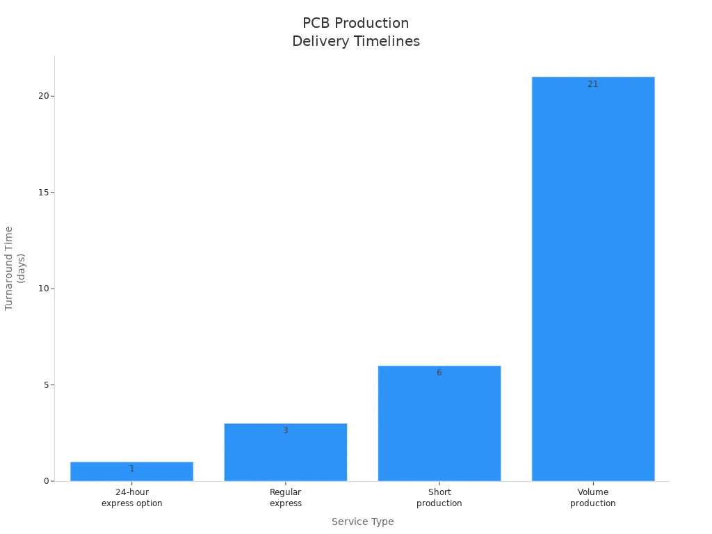
You can select the best service based on your project needs and budget. Fast turnaround options help you meet urgent deadlines, while volume production suits larger orders. Always confirm lead times and shipping methods with your supplier. If you need updates or have special requirements, reach out to the manufacturer’s support team. This approach keeps your flex project on track and ensures smooth delivery.
You can achieve reliable results when you follow each step in the design and ordering process for a flexible circuit. Focus on careful material selection, clear communication, and attention to detail at every stage.
- Review your flex pcb requirements and choose the right type for your application.
- Prepare accurate files and confirm all specifications with your manufacturer.
- Submit your order and request a price quote for your pcb project.
Reach out through the website for fast support, expert advice, or a quick quote on your next flex solution.
FAQ
What is the minimum bend radius for a flex circuit?
You should follow your manufacturer’s guidelines for minimum bend radius. Most recommend a radius at least ten times the thickness of the flex material. This helps prevent cracking and ensures long-term reliability.
How do I choose the right pcb surface finish?
You select a surface finish based on soldering needs and durability. ENIG works well for long-term reliability. HASL suits cost-sensitive projects. Ask your supplier for recommendations that match your assembly process.
Can I include stiffeners in my flex design?
You can add stiffeners to support connectors or components. Specify the location and type during the design phase. Stiffeners improve mechanical strength and help your flex circuit last longer.
What files do I need to submit for manufacturing?
You need to upload Gerber and Excellon files. These formats contain all the details for production. Double-check your files for accuracy before submitting them through the website portal.
How do I get a price quote for my project?
You request a price quote by uploading your design files and project details on the supplier’s website. Fast support teams can answer questions and help you optimize your order.
.png)
.png)
.png)
.png)

.png)

