


 2025-07-03
 BEST
BESTFlexible printed circuit boards rely on several material categories: substrate, conductive layer, adhesives, coverlay, and optional layers. The substrate forms the flexible foundation, while the conductive layer creates electrical pathways. Adhesives bond layers together, and coverlay protects circuits from external damage. Optional layers, such as stiffeners, enhance structural support in flexible circuit boards. Material selection in flex PCB material directly affects flexibility and durability, with engineering data showing that proper substrate thickness and type improve bend radius and flex cycle endurance. Bestfpc prioritises reliable, high-performance flex PCB materials for advanced flexible circuits.
Key Takeaways
- Flexible PCBs use different materials like substrates, conductive layers, adhesives, coverlay, and optional layers to ensure flexibility and durability.
- Polyimide film is the top substrate choice for tough applications due to its heat resistance and ability to bend many times without damage.
- Copper foil types, such as rolled-annealed (RA) and electro-deposited (ED), affect the PCB's flexibility and are chosen based on how much the circuit will bend.
- Adhesives and coverlay protect and hold the layers together, with acrylic adhesives and polyimide coverlay offering good flexibility and protection.
- Adding optional layers like stiffeners and EMI shielding improves support and signal quality without reducing overall flexibility.
Flex PCB Material: Substrates
Flexible PCBs depend on the right substrate to achieve the required flexibility, reliability, and performance. The substrate acts as the base layer, supporting the conductive traces and other layers. Polyimide and polyester (PET) films are the most common flexible substrates, each offering unique advantages for different applications. Adhesiveless substrates have also become important for high-reliability circuits.
The global market for flexible PCB substrates continues to grow rapidly, with organic substrates dominating the segment. Industry standards such as JEDEC and IPC ensure quality and reliability in flexible PCB production.
| Key Market Statistics and Insights | Details |
|---|---|
| Market Size (2024) | USD 40.34 billion |
| Projected Market Size (2033) | USD 90.18 billion |
| CAGR (2025-2033) | 9.35% |
| Largest Regional Market | Asia-Pacific |
| Fastest Growing Region | North America |
| Dominant Substrate Material Segment | Organic substrates |
| Major Market Players | Amkor, ASE Group, Henkel, Hitachi Chemical, Sumitomo Bakelite, LG Chem, Powertech, Toray |
| Relevant Industry Standards | Purpose |
|---|---|
| JEDEC J-STD-020F | Moisture sensitivity classification |
| IPC-A-600 | Visual acceptability of PCBs |
| IPC-2221 | Generic PCB design standards |
Polyimide Film
Polyimide film stands out as the leading flex PCB material for demanding applications. This substrate offers outstanding thermal stability, mechanical strength, and chemical resistance. Polyimide supports repeated bending and flexing without cracking, making it ideal for dynamic flexible circuits.
| Material (Polyimide Film) | Tensile Strength (MPa) | Elongation at Break (%) | Young's Modulus (GPa) | Thermal Stability (°C) | Self-Healing Efficiency (%) |
|---|---|---|---|---|---|
| IPIN | 4.28 | 250 | N/A | >160 | 50.04 (after 5 min) |
| PIM-4 | 94.5 | 6.1 | 3.5 | 434 | N/A |
| CO-PIM-75 | 62.5 | 12.9 | N/A | >242 | N/A |
| PGCS-100 | 56.5 | 20.6 | 0.439 | 227.1 | Up to 97.8 |
| PI-A1.0/T1.0 | 55.2 | 72 | 1.7 | N/A | N/A |
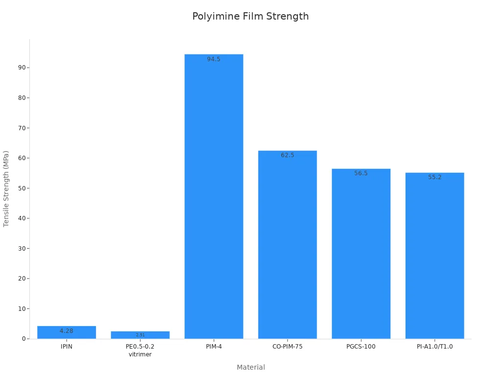
Polyimide film maintains high flexibility and durability, even after thousands of flex cycles. It resists heat and chemicals, which is essential for aerospace, automotive, and medical applications. Polyimide-based flexible copper-clad laminate provides a stable platform for fine circuit patterns. The material’s low dielectric constant and low water absorption further enhance signal integrity and reliability.
Polyester (PET) Film
Polyester (PET) film serves as a cost-effective and lightweight flexible substrate. PET offers good electrical insulation, moderate thermal resistance, and excellent flexibility. This material is popular in consumer electronics, wearable devices, and flexible displays.
| Substrate | Dielectric Constant | Dielectric Loss | Thickness |
|---|---|---|---|
| PET | 2.63 | 0.004 | 0.5 mm |
| Kapton | 3.5 | 0.002 | 100 μm |
| PDMS | 2.65 | 0.02 | 2 mm |
| LCP | 3.16 | 0.025 | 4 mm |
| Paper | 1.9 | 0.025 | 100 μm |
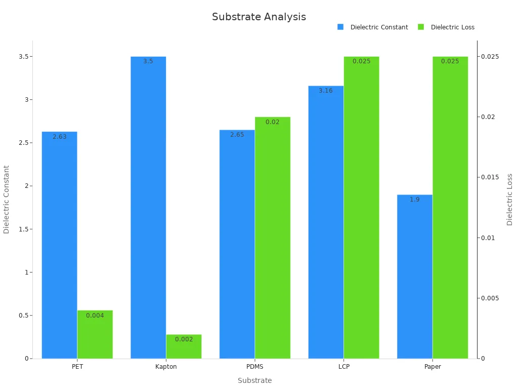
PET film balances flexibility and electromagnetic performance. It maintains stable antenna gain, even when bent, which is important for flexible antennas and wearable technology. PET’s low dielectric loss and moderate thickness make it suitable for applications where comfort and repeated bending are required. While Kapton and LCP offer better dielectric stability for high-frequency circuits, PET remains a preferred choice for cost-sensitive and lightweight designs.
Adhesiveless Substrates
Adhesiveless substrates use a direct bonding process to attach copper foil to the flexible base film, eliminating the need for adhesive layers. This approach improves flexibility, reduces thickness, and enhances reliability. Adhesiveless flexible substrates show better resistance to delamination and thermal stress, which is vital for high-reliability flex PCB applications.
Manufacturers select adhesiveless substrates for circuits that require repeated flexing, fine line patterns, or exposure to harsh environments. The absence of adhesive also reduces outgassing and improves dimensional stability. These benefits make adhesiveless laminate a top choice for advanced medical, military, and aerospace applications.
Tip: Choosing the right substrate material ensures the flex PCB meets the required flexibility, durability, and performance for its intended application.
Flexible PCB Conductive Layers
The conductive layer forms the electrical pathways in a flexible PCB. This layer allows signals and power to travel across the circuit. Most manufacturers use copper foil for this purpose because it offers excellent conductivity and reliability. The choice of copper type affects the performance and durability of the flexible circuit.
Copper Foil Types
Manufacturers select different copper foil types based on the needs of the flexible PCB. The two main types are rolled-annealed (RA) copper and electro-deposited (ED) copper. Each type has unique properties that suit specific applications.
Tip: The right copper foil type can improve the lifespan of a flexible circuit, especially in devices that bend or move often.
| Copper Foil Type | Flexibility | Grain Structure | Typical Use |
|---|---|---|---|
| RA Copper | High | Elongated | Dynamic |
| ED Copper | Moderate | Columnar | Static |
Rolled-Annealed (RA) Copper
RA copper starts as a solid copper ingot. Manufacturers roll and heat it to create thin, flexible sheets. This process gives RA copper a fine, elongated grain structure. RA copper bends easily and resists cracking. Engineers use RA copper in flexible circuits that need to move or flex many times, such as in wearable electronics or medical devices. The high flexibility of RA copper makes it ideal for dynamic applications.
Electro-Deposited (ED) Copper
ED copper forms by depositing copper ions onto a rotating drum in a chemical bath. This method creates a columnar grain structure. ED copper costs less than RA copper and works well in flexible PCBs that do not require frequent bending. Static applications, such as display connectors or simple interconnects, often use ED copper. While ED copper offers good conductivity, it does not match the flexibility of RA copper.
Note: Choosing between RA and ED copper depends on how much the flexible PCB will bend during its lifetime.
Flexible PCBs rely on the right copper foil to balance cost, flexibility, and performance. RA copper suits dynamic, high-flex environments, while ED copper fits static, cost-sensitive designs.
Flex PCB Materials: Adhesives & Coverlay
Adhesives and coverlay play a vital role in the construction of flexible PCBs. Adhesives bond the different layers together, while coverlay protects the circuits from moisture, dust, and mechanical damage. These materials help maintain the integrity and performance of the flexible circuit, especially in demanding environments.
Adhesive Types
Manufacturers use adhesives to attach copper foil to the substrate and to bond coverlay to the circuit. The most common adhesive types in flexible PCBs are acrylic and epoxy. Acrylic adhesives offer excellent flexibility and good resistance to heat and chemicals. They suit applications where the circuit will bend or flex repeatedly. Epoxy adhesives provide strong bonds and high thermal stability. Engineers often choose epoxy for circuits that require extra durability or will face high temperatures. Both adhesive types ensure that each material layer stays firmly in place during the PCB’s lifetime.
| Adhesive Type | Flexibility | Heat Resistance | Typical Use |
|---|---|---|---|
| Acrylic | High | Moderate | Dynamic |
| Epoxy | Moderate | High | Static |
Polyimide Coverlay
Polyimide coverlay acts as a protective layer for flexible circuits. This material consists of a thin polyimide film coated with adhesive. Polyimide coverlay shields the copper traces from environmental hazards and mechanical stress. It also provides electrical insulation and helps the flexible PCB maintain its shape during repeated bending. Polyimide coverlay remains stable at high temperatures and resists chemicals, making it ideal for automotive, aerospace, and medical devices. Engineers rely on this material to extend the lifespan of flexible circuits in harsh conditions.
Solder Mask Options
Some flexible PCBs use a liquid solder mask instead of a coverlay. Solder mask is a polymer-based material that protects the circuit from oxidation and prevents solder bridges during assembly. While coverlay offers better mechanical protection, solder mask provides a thinner and more precise coating. Designers may choose solder mask for flexible circuits with fine-pitch components or where space is limited. Both options help safeguard the flexible PCB and ensure reliable performance.
Tip: Selecting the right adhesive and coverlay material improves the durability and flexibility of the finished circuit.
Optional Layers
Flexible PCBs often require extra layers to meet specific mechanical or electrical needs. These optional layers include stiffeners, EMI shielding, and conformal materials. Each layer serves a unique function and helps the circuit perform better in demanding environments.
Stiffeners
Stiffeners add mechanical support to flexible PCBs. Engineers use materials such as FR4, polyimide, or stainless steel for stiffeners. These materials help the flexible circuit keep its shape during assembly or when connectors are attached. Stiffeners prevent unwanted bending in certain areas, which protects delicate components and solder joints. Designers often place stiffeners under connectors or mounting points. This approach ensures the PCB stays flat and strong where needed.
Stiffeners do not affect the flexibility of the entire circuit. They only reinforce specific sections that need extra strength.
EMI Shielding
Electromagnetic interference (EMI) can disrupt signals in flexible PCBs. EMI shielding blocks unwanted electrical noise and keeps signals clean. Engineers use materials such as copper foil, conductive tapes, or special coatings for shielding. These layers cover sensitive traces or the whole circuit, depending on the application. EMI shielding is important in medical devices, automotive electronics, and communication equipment. It helps the circuit meet strict industry standards for signal integrity.
Conformal Materials
Conformal materials protect flexible PCBs from moisture, dust, and chemicals. These coatings form a thin, flexible layer over the circuit. They keep the PCB safe in harsh environments and extend its lifespan. Recent studies show that advanced conformal materials can improve both mechanical and electrical performance. For example, capillary-stabilised liquid bridges increase the stretchability of gold films on flexible substrates from 30% to 180%. Electrical percolation strain also rises from about 10% to 160%. Small cracks remain dispersed below 80% strain, while circuits without these materials develop large cracks at just 10% strain.
| Parameter | Value (With Liquid Bridges) | Value (Without Liquid Bridges) |
|---|---|---|
| Stretchability of Au film | 180% | 30% |
| Electrical percolation strain | Up to 160% | ≈10% |
| Crack behaviour | Dispersed small cracks below 80% strain | Penetrating cracks at ≈10% strain |
Researchers have also used inkjet printing to create flexible devices on polyimide and PET substrates. They select materials such as gold and silver inks, carbon nanotubes, and various polymers. Careful processing and material choice help these conformal coatings protect circuits while keeping them flexible.
Tip: Adding the right optional layers can make a flexible PCB more reliable and suitable for tough applications.
Material Selection
Application Matching
Selecting the right flex PCB material starts with understanding the requirements of the application. Engineers look at the environment, expected movement, and electrical needs. For wearable devices, flexibility and comfort take priority. Medical and aerospace applications demand high reliability and resistance to chemicals. Consumer electronics often require lightweight and cost-effective solutions. Common applications of flex PCBs include mobile phones, cameras, and automotive sensors. Each of these uses flexible printed circuit boards to achieve unique shapes and reliable connections. Matching the correct material ensures the flexible circuit boards perform well and last longer.
Performance Factors
Performance and durability depend on several factors. Engineers consider the flexibility of the substrate, the strength of the adhesive, and the protection offered by coverlay or solder mask. They also test the copper layer for its ability to handle repeated bending. Reliability studies, such as those defined by MIL-PRF-61002, include:
- Enhanced thermal cycling to simulate extreme temperature changes
- Mechanical stress durability testing for exceptional durability
- Moisture protection assessments to prevent water damage
- Chemical resistance evaluations
- Electrical performance checks under different conditions
The MIL-PRF-61002 B revision introduces stricter material qualification and advanced testing protocols. These studies help engineers choose flex PCB materials that meet the highest standards for flexible circuit boards.
Bestfpc’s Approach
Bestfpc uses a careful process to select materials for flexible printed circuit boards. The team reviews the application, environment, and expected flex cycles. They recommend the best flex PCB material for each project, balancing flexibility, durability, and cost. Bestfpc works with trusted suppliers and tests every batch to ensure quality. Their expertise helps customers get flexible circuit boards that meet strict requirements for flexibility and reliability. Bestfpc’s approach ensures that each flexible PCB delivers strong performance in its intended application.
Selecting the right materials for printed circuit boards shapes their performance and reliability. Each category—substrate, conductive layer, adhesives, coverlay, and optional layers—plays a unique role in protecting and supporting printed circuit boards. Careful material selection helps engineers achieve the best results for each application.
- Substrates provide the base.
- Conductive layers carry signals.
- Adhesives and coverlay protect and bond.
- Optional layers add support or shielding.
For expert advice on printed circuit boards, consult Bestfpc or a trusted supplier.
FAQ
What is the most common substrate in flexible PCBs?
Polyimide film is the most common substrate. It offers excellent flexibility, heat resistance, and durability. Engineers choose polyimide for demanding applications in aerospace, automotive, and medical devices.
Why do engineers use adhesiveless substrates?
Adhesiveless substrates improve flexibility and reduce thickness. They also resist delamination and thermal stress. These benefits make them ideal for high-reliability circuits in harsh environments.
How does RA copper differ from ED copper?
RA copper has an elongated grain structure, which allows it to bend easily without cracking. ED copper has a columnar grain structure and suits static applications. RA copper works best for circuits that flex often.
When should designers add stiffeners to a flexible PCB?
Designers add stiffeners when certain areas need extra support. Stiffeners help the PCB stay flat during assembly or when connectors are attached. They do not affect the flexibility of the rest of the circuit.
Can flexible PCBs use solder mask instead of coverlay?
Yes, flexible PCBs can use a liquid solder mask. Solder mask provides a thin, precise protective layer. It works well for circuits with fine-pitch components or limited space.
.png)
.png)
.png)
.png)

.png)

