With the growing of the era of big data, electronic devices existing in everywhere we can see, everything from our smart phones to our cars includes electronic components. Most of people know the green core are the FPC bare board, but don’t know how to keep those electronic components on the bared FPC. Here we give you a brief introduction and its processes.
The process about mounting/soldering components on a bared circuit we called it as Printed Circuit Board Assembly, or short for “PCBA”, it is produced by Surface Mount Technology (SMT), it is an aspect of electronic assembly where electronic components, also called surface mount devices (SMD), are directly mounted components onto the surface of a printed circuit board.
What is Surface Mount Technology (SMT)?
Initially called Planar Mounting, the United States is the place where SMT was invented. Since 1963, when the first surface mount component appeared in the world and Philips launched the first surface mount integrated circuit, SMT has been mainly applied in highly sophisticated industries such as military, aviation and aerospace in the initial stage and gradually widely applied to computer, communication, military, industrial automation, consumer electronic products and other industries with the rapid development of electronics. SMT is growing very fast. When comes into 1980s, SMT technology has become the most popular new generation of electronic assembly technology in the world, known as a revolution in electronic assembly technology. Up to now, SMT already became a mature mounted technology in PCB industry, which can solder various electronic components on PCB surface, including resistors, capacitors, connectors, ICs, micro-chips, LEDs, DIP components, wires and so on... We know the components was solder on PCB, how? How to solder it and what we should pay attention to before SMT process?
Before SMT Manufacturing Process

A few preparation steps have to happen before starting a formal PCBA process. This helps PCB manufacturers assess the functionality of a PCB design, and primarily includes an engineering file check, here I mainly introduce about engineering file check, for other details you can click http://www.bestpcbs.com/blog/2022/02/what-should-be-prepared-before-starting-the-smt-process/
Engineering file check looks at all the design specifications. Specifically, it includes Bill of Material (BOM) check, Pick and Place, Silkscreen drawing, Orientation of Components and program of assembly. This check looks for any missing, redundant or potentially problematic features. Any of these issues may severely and negatively influence the functionality of the final project. For example, an actual component isn’t match with its pad, maybe it is a wrong specification or maybe the purchase make a mistake.
By identifying potential problems before manufacturing begins, engineering file checks can cut manufacturing costs and eliminate unforeseen expenses. This is because these checks cut down on the number of scrapped boards and components loss during assembly. As part of our commitment to quality first, engineer file check comes standard with every assembly order, Best Tech dedicate to offer good quality products to our customers.

A formal SMT process started
1.Solder Paste Printing:
This is a crucial step of assembly process, during this step, the solder paste will be applied on the soldering pads through stencil by a printer, generally, we also print the solder paste by manually, but it needs a squeegee (a tool for cleaning in printing) at an angle ranging from 45° to 60°, in this angle, the solder paste can be applied on the pads perfectly and flatness. Flux is a chemical mixture, is an auxiliary material serves as a temporary glue to hold the surface mount components in place as well as cleansing the soldering surfaces of impurities and oxidation. And in another way, we can say solder paste can ensure the smooth of welding process and the performance of flux can directly affects the quality of electronic products. Solder paste composed of 96.5% tin, 0.5% copper and 3.0% silver, Best Tech commonly use SAC305 solder paste.
Before printing solder paste, a professional operator uses a mechanical fixture holds the PCB and solder stencil in a place. Then places solder paste on the intended areas in precise amounts. The machine then spreads the paste across the stencil, applying it evenly to every open area (where we leave for solder pads). After removing the stencil, the solder paste remains in the intended locations.

2. Components Placement (Pick and Place)
Next process, placement machines are used to place SMD components on the PCB, this step requires a Pick and Place file from customers, of course, no pick and place file also is okay, but this will cause wrong place and low efficiency. Each component is removed from its packaging using a vacuum or a feeder nozzle, and the placement machine places it in its designed location. The PCB is carried on a conveyor belt while the electronic components are placed on it by the quick and accurate machines, some of which can place 80,000 individual components per hour, and our FX-3RAL high speed placement machine can achieve 90,000 components per hour.

3. Reflow Soldering
After placement, most of standard SMDs (some irregular and large components can’t to be placed in pick and place machine) are soldered on the circuit board surface, now we should remain them and through a “Reflow” process to ensure a good solderability and solidify quickly. Reflow process happened in a long and large oven, where it passes through the following zones to undergo the soldering process:
Soak zone (1-3zone): this is the first zone in the oven, where the temperature of the board and all the attached components is raised up gradually. The temperature of preheat zone is cranked up at the rate of 1.0℃-2.0℃ per second until it enters 125℃-165℃.
Preheat zone (4-7zone): here, the board will be kept at a temperature between 170℃ and 190℃ for 60-90 seconds.
Reflow zone (8-9zone): the boards then enter formal reflow zone where the temperature is go up at 1.0℃-2.0℃ per second to the maximum of 245℃-250℃ to melt the tin in the solder paste, welding the component leads to the pads on the PCB. While this is going on, the components are kept in place by the surface tension of the molten solder.
Cooling zone (10zone): this is the final section that ensures solder freezes upon exiting the heating zone to avoid joint defects, and in this zone, the temperature kept around 230℃. Note: All the temperature mentioned above is the reflow temperature ONLY used for normal aluminum board and copper board, different kind of board required a different temperature.
A whole reflowing process generally spend around 7-8 minutes and if the printed circuit board is double-sided then these processes should be repeated using either solder paste or glue to hold the SMDs in place.
4. Inspection and Quality Control
After reflowing, the board is cleaned and checked for flaws. If any is found, the defects are repaired and then the product is stored. The most common ways used for SMT inspection are include:

AOI (Automated Optical Inspection)
AOI machine using the optical principle, the camera on the equipment scans PCBAs, collects images, and compares the collected solder joint data with the qualified data of the machine database, and mark PCBA soldering status after image processing. Different quality solder connections reflect light in different ways, allowing the AOI to recognize a lower-quality solder. Using AOI inspection can improve production efficiency, save labor cost and unified detection standards.
X-ray inspection
X-ray equipment mainly uses the penetration of X-ray rays to detect whether the BGA components are false soldering. For more information about X-ray, please click http://www.bestpcbs.com/blog/2022/06/x-ray-inspection-in-pcb-assembly/
5. Post-welding
Post-welding processing refers to the circuit board after reflowing, for some components that are not suitable for wave soldering (such as through-hole components, wires, Tantalum Capacitors and so on) through manual soldering with electric iron. There are some reasons include why need to do post-welding:
The components are not resistant to high temperature
Nowadays, lead-free technology is becoming more and more popular. The temperature in the furnace is higher than that of the lead when soldering through the wave. Therefore, some components that are not resistant to high temperature cannot pass wave soldering.

The components are too high
Wave soldering is limited to the height of components, components will be too high to lead to wave welding.
There are a few plug-ins on the side of the wave
In a circuit board, there will be some plugins on the over-wave soldering side, if it is a small number of plugins, then you can use the post welding to improve efficiency.
Component plug-in is close to the process edge
The position of the component plug-in near the board edge will encounter the assembly line, which will affect the normal welding.
Special components
For sensitive components with special requirements of customers, wave soldering is not allowed.
Post welding is a very important welding method in PCBA processing, which can make up for the shortcomings of wave welding and improve the welding efficiency. When the whole soldering process be finished, we can move to next step – final inspection.
6. Final Inspection
Final inspection includes appearance inspection and functional inspection. Before performing inspection, we know the whole soldering process is complex and filthy, the most obvious one is solder paste leaves some flux while operators or repairers manually soldering, and at the same time, some stains leave from their fingers and clothing to the PCBA surface, this requires a alcohol cleaning to remove those dirties.
Then IPQC inspect the PCBAs one by one to check component missing, dirty on surface, copper exposure or burrs on the edge issues.

A functional inspection will test the PCBA for its functionality. In this process, Best Tech always customize a special testing jig for performance test if it is mass production, and for small quantity and prototypes, the test puts the FPC through its paces, simulating the normal circumstances in which the FPC will operate. Power, voltage, resistance and simulated signals run through the FPC in this test while testers monitor the FPC's electrical characteristics. If the detector detects some signal over its normal value, then it means the testing failure and now our inspector will pick it out and ask for a repair.
Once IPQC inspection completed, QA inspectors will random inspect the FPC Assembly (include performance test) to double check they are in good quality.
Testing is the final and most important step in FPC assembly process, as it determines the success or failure of the process. That’s why Best Tech put much attention to the SMT operator trains and studies, we want to make sure all of our operators have this capability to inspect out defective board and all of them can serve as IPQC when QCs are busying to checking.
When above steps be finished and there is no other failure, then we can say your FPC assembly process are completed.
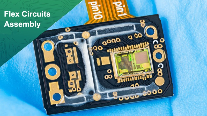
And maybe there are some designers will ask: does flexible FPC can assembly? -- Yes, of course, as above picture shown, you also can see the assembled FPC. However, FPC is the more difficult to assemble than PCB. As we know, flexibility is good feature of FPC, but also because of its flexibility, we should take more attention to it when assembly, since it is easier to occur false welding. So in order to solve this problem, some designers will request to stick stiffener on the surface, which will convenient for assembling.
Now because of its cheap price, good features and small volume, FPC assembly is widely used in most of areas, such as mobile phone, computer port, flex sensor, Flex Flat Cable, battery charger and so forth.
Choose Best Technology
As a professional FPC manufacturer in Asia, Best Technology offers premier solutions and One-Stop service to customers from flexible circuits bare board manufacturing, electronic components sourcing to PCB Assembly.

Our assembly service certificated by RoHS, ISO9001 and ISO13485 quality system, we proceed each step of the way conform to IPC quality standard, so when you choose Best Technology as your FPC assembly supplier, you’re choosing a best partner with quality assurance and on time delivery.
In addition, we can assemble any kind of circuit boards, whatever it is FPC Board, Rigid-flex PCB, FR4 PCB, Ceramic PCB, Metal Core PCB or Sink PAD PCB, whether it is double side or single side, we all can do.