


 2024-05-23
 BEST
BESTA Flexible Printed Circuit Board (Flex PCB) is a highly versatile electronic component made from a flexible polyimide or polyester film. These boards are designed to bend and flex, making them ideal for modern electronic devices where space is at a premium and complex configurations are necessary. The importance of Flexible Printed Circuit Board design cannot be overstated, as it directly impacts the functionality and reliability of devices ranging from precision medical equipment to everyday consumer electronics. BEST FPC, a prominent manufacturer in Asia, is committed to producing top-tier Flexible Circuits and PCBs, aiming to meet the growing demands of both global industries and everyday consumers.
Understanding Flex PCB Materials
Types of Substrates
Flexible PCBs utilize various substrates to ensure flexibility and durability. The most common substrates include polyimide (PI), polyester (PET), and polyethylene naphthalate (PEN). These materials are chosen for their excellent thermal stability, chemical resistance, and mechanical properties.
Material Selection Criteria
When selecting materials for Flex PCBs, several factors must be considered:
- Thermal endurance: The material must withstand the temperatures encountered during both manufacturing and operation without degrading.
- Electrical properties: High dielectric strength and low dielectric constant are crucial for effective insulation and minimal signal loss.
- Mechanical flexibility: The material should be capable of bending and flexing without breaking, particularly important for dynamic applications.
Considerations for Flexible Circuitry
Designing flexible circuits requires special considerations to maximize reliability and performance:
- Bend radius: A tighter bend radius can lead to increased stress on the circuit, potentially causing cracks or component failure.
- Circuit layout: Strategic placement of components can help distribute stress evenly across the PCB during flexing.
- Adhesive selection: Choosing the right adhesive is critical for ensuring that layers of the Flex PCB remain intact under stress.
Best FPC Flex PCB Design Innovation
Flexible Circuit Board Design
At Best FPC, we distinguish between OEM and ODM PCB design tailored to customer purposes:
- OEM Flex PCB Design: Factories produce batches according to the original designs and materials provided by the customers.
- ODM PCB Design: After understanding the customer's product applications and performance parameters, Best FPC offers customized design and IC material selection.
ODM Flex PCB Design
Schematic Drawing For Your Specified Product: We provide bespoke design services based on application requirements such as performance, impedance, current, voltage, and bending cycles, without needing a prior schematic diagram.
Custom Printed Design Flex Circuit Layout: For clients less familiar with PCBs or those updating products iteratively, our engineers design the shape and wiring based on the product's specifications, utilizing our 16 years of industry experience to provide optimal ODM design solutions.
OEM FPC Routing
Engineer Reviews Client's Files: Customers submit their design files in formats like Gerber or Boom, and our engineers review and confirm the viability of production. This stage helps identify any design flaws and suggest cost-effective material alternatives that meet quality standards.
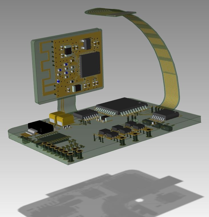
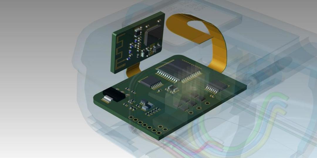
3D PCB Display
Enhanced Visualization and Verification: The 3D model displays enable a comprehensive review of the PCB's design from all angles, ensuring that no potential design issues are overlooked. After validation by our engineering team, the PCB can move to prototyping or mass production, with each parameter meticulously verified through instrumentation.
Manufacturing and Assembly Best Practices
The era of big data has transformed our lives, embedding electronic devices in everything from smartphones to vehicles. While many recognize the familiar green core of a Flexible Printed Circuit (FPC) board, few understand the critical steps required to attach electronic components to these bare boards. Here, we outline the essential processes involved.
Surface Mount Technology (SMT)
Printed Circuit Board Assembly (PCBA) is the process where electronic components, known as Surface Mount Devices (SMD), are mounted onto the surface of an FPC. This process begins with applying solder paste to the soldering pads using a stencil through a printer. Although solder paste can also be applied manually, it requires using a squeegee at an angle between 45° to 60° to ensure perfect, flat application on the pads.
The Role of Flux and Solder Paste
Flux, a chemical mixture, acts as a temporary adhesive holding the components in place and cleaning the soldering surfaces of impurities and oxidation. The quality of flux significantly affects the outcome of the soldering process and, by extension, the quality of the electronic product. Best Tech typically uses SAC305 solder paste, composed of 96.5% tin, 0.5% copper, and 3.0% silver, for its excellent soldering properties.
Testing and Quality Assurance
Ensuring the reliability of electronic components through rigorous testing is critical. Below are some of the advanced methods used:
AOI (Automated Optical Inspection)
This technique involves an AOI machine using cameras to scan PCBAs and collect images. These images are then compared to a database of qualified solder joint data to evaluate the soldering quality on the PCBAs. Different qualities of solder connections reflect light differently, enabling the AOI to detect lower-quality solders. This method enhances production efficiency, reduces labor costs, and standardizes detection criteria.
X-Ray Inspection
X-ray equipment detects issues like false soldering in Ball Grid Array (BGA) components by utilizing the penetrating power of X-ray rays.
Testing Protocols
- In-Circuit Testing: Tests electrical performance to ensure components and circuits function correctly.
- Mechanical Stress Testing: Assesses the PCB's ability to withstand physical stresses it might encounter during its lifecycle.
- Environmental Testing: Examines how environmental factors such as temperature and humidity affect the PCB.
- Reliability Testing: Evaluates the longevity and durability of the PCB under repeated stress conditions.
Case Studies and Examples
Real-World Applications of Flex PCBs
Flex PCBs are utilized in a variety of sectors due to their flexibility and resilience, allowing them to fit into tight and unconventional spaces in advanced electronic devices.
Success Stories and Lessons Learned
Case studies highlight the pivotal role Flex PCBs have played in enhancing product design and functionality across multiple industries. These examples not only showcase the adaptability and efficiency of Flex PCBs but also impart valuable lessons in design and application, contributing to the continuous improvement of electronic manufacturing practices.
In Conclusion
Adopting best practices in Flex PCB design is crucial for ensuring the durability and functionality of electronic devices. This involves selecting appropriate materials, utilizing advanced manufacturing techniques such as Surface Mount Technology, and adhering to rigorous testing protocols like AOI and X-ray inspections. By integrating these methods, designers and manufacturers like Best Tech can optimize the performance and reliability of Flex PCBs. Embracing these standards not only enhances product quality but also positions companies to lead in the competitive landscape of electronics manufacturing, meeting the demands of an increasingly digital world.
.png)
.png)
.png)
.png)

.png)

