


 2023-10-25
 BEST
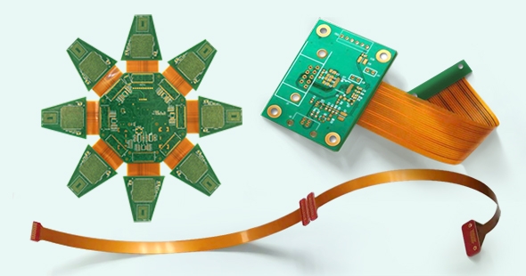
BESTA Rigid-Flex Printed Circuit Board (PCB) represents an advanced and hybrid circuitry solution, blending the benefits of both hardboard (rigid PCB) and flexible circuits (flex PCB). It comprises multiple layers of flexible circuit substrates attached to one or more rigid boards. These are designed to be in a continuous application where both the strength of the rigid boards and the flexibility of the flex circuits are required.
The evolution of modern electronics is synonymous with the relentless pursuit of miniaturization while maximizing functionality. As devices become more compact, designers face the challenge of fitting increasingly complex circuits into smaller footprints.
Advantages of Rigid-Flex PCB Design
Rigid-flex PCBs, a type of Printed Circuit Board design, offer several significant advantages across various applications. Below are key benefits associated with the utilization of rigid-flex PCBs:
Space-saving and Weight Reduction
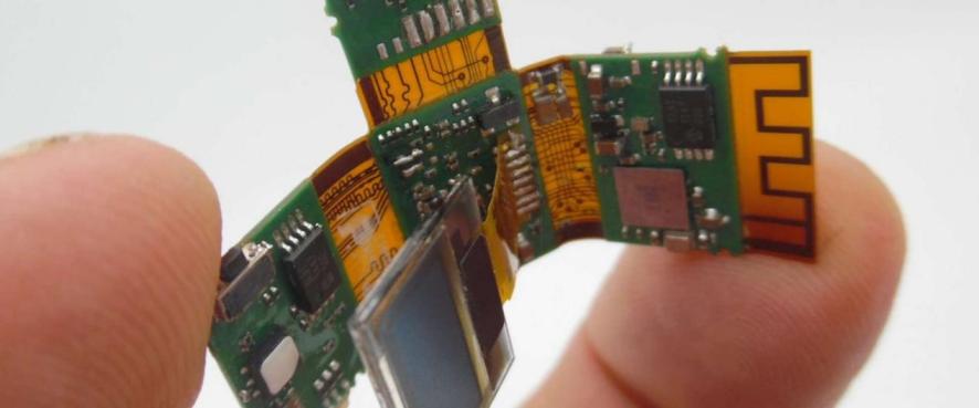
Rigid-flex PCBs exhibit exceptional form-factor flexibility, enabling designers to fold or bend them to snugly fit within confined spaces or unconventional shapes. This adaptability translates into valuable space savings within electronic devices, resulting in enhanced compactness and reduced overall weight.
Enhanced Reliability and Durability
Engineered to endure mechanical stresses like bending and flexing, rigid-flex PCBs maintain their structural integrity and electrical performance. This robustness enhances their reliability and durability, minimizing the risk of failures due to physical strains.
Cost-Effectiveness for Long-Term Projects
While the initial manufacturing cost of rigid-flex PCBs may surpass that of traditional rigid PCBs, they prove cost-effective in extended projects. They can replace multiple individual PCBs and connectors, reducing assembly and maintenance expenses, as well as the potential for connector failures over time.
Seamless Integration of Multiple PCBs
Rigid-flex PCBs facilitate the seamless amalgamation of multiple PCBs into a unified unit. This eliminates the need for connectors and cables, streamlining the design's overall complexity and enhancing signal integrity. Moreover, it simplifies the assembly process while diminishing the likelihood of connection errors.
Enhanced Signal Integrity
Thanks to their absence of connectors and shorter signal paths, rigid-flex PCBs offer superior signal integrity. This translates to superior signal quality, reduced electromagnetic interference (EMI), and overall improved electronic device performance.
Key Design Principles for Rigid-Flex PCB
Designing a Rigid-Flex PCB entails adhering to several fundamental principles to guarantee optimum functionality, reliability, and manufacturability. The following are essential guidelines for creating rigid-flex PCBs:
Comprehending Flex and Rigid Zones
It is imperative to possess a clear comprehension of the flexible and rigid regions within your design. Place flexible sections in areas requiring bending or flexing, while employing rigid zones for components or sections necessitating stability. Accurately defining these regions is crucial to ensure that the PCB bends and flexes as intended, safeguarding vital components from damage.
Utilization of Suitable Software and Design Tools
Employ dedicated PCB design software and tools designed to accommodate rigid-flex designs. These tools allow you to delineate and visualize flexible and rigid areas, manage layer stack-ups, and guarantee proper connectivity between them. This ensures that your design satisfies both mechanical and electrical prerequisites.
Adherence to the Bend Radius
One of the pivotal aspects of rigid-flex PCB design is adherence to the prescribed bend radius. The bend radius represents the minimum permissible curvature at which the flexible segment of the PCB can flex without inducing stress or harm to copper traces, vias, or components. Failing to conform to bend radius specifications can result in electrical and mechanical complications, including signal degradation and breakage.
Incorporation of Strain Alleviation
To avert excessive mechanical stress on the flexible segments of the PCB during bending or flexing, it is indispensable to integrate strain relief features. These may encompass teardrop-shaped pads, rounded corners, or additional material in high-stress zones. Adequate strain relief facilitates even distribution of mechanical stress, thereby diminishing the likelihood of PCB failure.
Consideration of ZIF Connectors, Shielding, and Grounding
In the context of rigid-flex designs, deliberate the use of Zero Insertion Force (ZIF) connectors in areas necessitating connections between rigid and flexible sections. Furthermore, implement sound shielding and grounding methodologies to mitigate electromagnetic interference (EMI) and ensure signal integrity. Proper grounding also contributes to the maintenance of a stable reference voltage throughout the entire PCB.
By heeding these fundamental design principles for rigid-flex PCBs, you can create designs that exhibit reliability, functionality, and manufacturability while meeting the specific requirements of your application.
Testing and Quality Assurance
Testing and quality assurance are pivotal phases in the production of rigid-flex PCBs, guaranteeing their functionality, dependability, and adherence to industry standards. Here are crucial facets of testing and quality assurance for rigid-flex PCBs:
Electrical Testing
Open & Short Testing: This procedure involves scrutinizing the PCB for open circuits (unintentional discontinuities) and short circuits (unintended connections). Specialized testing equipment is employed to confirm the continuity of conductive traces and pinpoint any faults.
Impedance Testing: Sustaining the correct impedance is paramount for preserving signal integrity in high-speed applications. Impedance testing validates that the electrical properties of the PCB align with design specifications, thereby reducing the risk of signal distortion.
Physical Testing
Bend & Flex Testing: Rigid-flex PCBs are engineered to bend and flex in designated areas. During testing, the PCB undergoes bending and flexing assessments to gauge its mechanical resilience. This ensures that the PCB can endure its intended use without harm or performance degradation.
Peel Strength Testing: This evaluation quantifies the adhesive bond's strength between the flexible and rigid layers of the PCB. Sufficient peel strength is indispensable to avert delamination or separation of the layers during bending or flexing.
Optical and X-ray Inspection
Optical Inspection: Visual examination employing magnification and optical instruments is employed to spot any apparent defects, such as solder joint irregularities or component placement issues.
X-ray Inspection: X-ray inspection is utilized to probe the inner structure of the PCB, including concealed solder joints and traces. This aids in detecting defects that might remain concealed to the naked eye, enhancing the reliability of the inspection process.
Ensuring IPC Standards Compliance
The IPC (Association Connecting Electronics Industries) has instituted industry standards governing PCB manufacturing and testing. Ensuring conformity with IPC standards is imperative for quality assurance. Manufacturers must adhere to specific IPC guidelines pertinent to rigid-flex PCBs to meet industry expectations regarding quality and dependability.
1) Functional Testing:
In addition to the aforementioned assessments, functional testing may be conducted to validate the PCB's performance under real-world conditions. This encompasses testing the PCB with actual components and simulating its intended application to ascertain that it meets functional prerequisites.
2) Environmental Testing:
Depending on the application, rigid-flex PCBs may be subjected to environmental tests to assess their performance under varying conditions, such as extreme temperatures, humidity, and vibration. This ensures the PCB's dependable operation within its intended environment.
3) Documentation and Traceability:
Comprehensive documentation and traceability are indispensable elements of quality assurance. This encompasses maintaining records of test results, inspection reports, and alignment with design specifications. Traceability facilitates the identification and rectification of any issues that may surface during testing or in the field.
Testing and quality assurance are integral in delivering rigid-flex PCBs that are reliable and meet the rigorous demands of contemporary electronic applications. Rigorous testing protocols enable the detection and correction of any defects before the PCBs are deployed in actual products, ensuring their enduring performance and reliability.
CONCLUSION
To sum up, achieving proficiency in the realm of Rigid-Flex PCB design and manufacturing is a complex undertaking that melds creativity, precision, and meticulousness. Rigid-flex PCBs stand as an exceptional solution for scenarios prioritizing space efficiency, dependability, and versatility.
Nevertheless, they pose distinct challenges that necessitate thoughtful deliberation and mastery to surmount. As technology progresses, the need for compact, resilient, and trustworthy electronic solutions remains ever-present. In this context, rigid-flex PCBs will maintain their critical role in satisfying these requirements.
.png)
.png)
.png)
.png)

.png)

