


 2026-01-04
 BEST
BEST
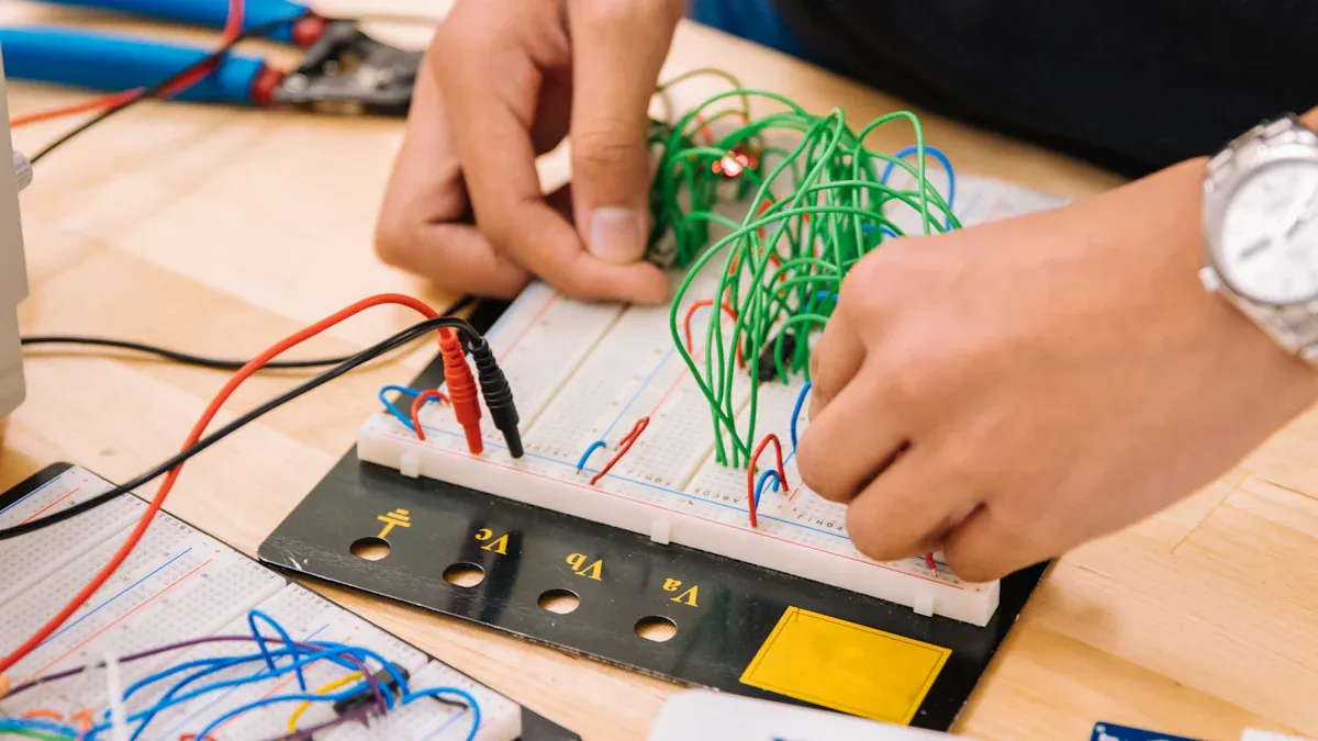
When you design a robot flexible board, you face special problems. These problems need careful thinking. Flexible pcbs in robotics must move a lot. They must fit in small spaces. They must work well all the time. Picking the right material for your flexible pcb is important. It helps the board last longer against water and bending. You also need to think about how much the board can bend. You must put the board together very carefully. You should also think about how much it costs. These problems make flexible pcbs different from other pcbs in robotics. Every choice you make is very important for success.
Key Takeaways
- Pick the best materials for flexible PCBs so they bend easily and do not break. Do not use standard prepreg with a lot of resin.
- Always follow the smallest bend radius rules. This stops copper from breaking or coming off. It is very important to keep the PCB safe when it moves.
- Keep parts away from flex zones. This stops the board from getting stiff or cracking. Mark these spots clearly so no one makes mistakes when putting it together.
- Make sure the stack-up is even in rigid-flex PCBs. This helps them bend the right way and fit well in robots. A balanced stack-up makes the board work better.
- Talk with manufacturers early and often. This helps find problems before making the board. Working together makes sure the design fits what the robot needs.
The Most Common Mistakes to Avoid When Designing Flexible PCBs for Robotics Applications
Making flexible pcbs for robots is hard. You need to watch out for mistakes. If you make a mistake, your board might not work. It could break, take longer to fix, or cost more money. Here are some mistakes and how they hurt flexible pcb performance.
Material Selection for Flexible PCBs
Pick materials that fit what robots need. Some designers use regular prepreg or forget low-flow types. These choices can make flexible pcbs stiff or easy to break. The table below shows mistakes and what happens:
| Mistake | Impact |
|---|---|
| Using standard prepreg with high resin content | Too much resin makes flexible parts stiff. |
| Not using no-flow or low-flow prepreg | The pcb can get stiff and not bend well. |
| Using fewer than 3 layers of prepregs | Air gaps can form and cause shorts. |
If you pick the wrong material, your flexible pcb may not bend right. This can cause cracks or shorts. Robots move a lot, so this is a big problem. Always follow rules for picking materials. This keeps your flexible pcb working well.
Bend Radius and Flex Zones
You must follow the minimum bend radius for flexible circuits. If you ignore this, copper can break or peel off. In robots, these problems happen when parts move or get hot and cold. Here are some things to remember:
- Acrylic adhesives in flex layers can stress copper barrels.
- Connections can fail when the board heats and cools.
- Use adhesive-less cores in rigid areas.
- Add teardrops to via pads for strength.
| Challenge | Empirical Solution / Best Practice |
|---|---|
| Bend radius considerations | Follow bend rules to stop breaks and signal loss |
| Mechanical reliability | Use anchors and teardrops, avoid sharp turns for strong traces |
| Copper breaks due to bending | Keep vias out of flex areas; run traces across bend lines |
| Trace lifting | Make traces bigger to stick better and lower stress |
Line up copper grain with the flex arm and use rolled annealed copper. This stops cracks and helps your flexible pcb last longer.
Trace Routing Issues
Trace routing in flexible printed circuit design needs care. Designers often make these mistakes:
- Running traces along the bend axis, which stretches them.
- Using traces thinner than 0.1mm, which can overheat.
- Putting vias in bend zones, which can crack.
Always run traces across bend lines. Do not put lots of vias in flex areas. This makes your flex circuits stronger and less likely to fail in robots.
Component Placement in Flex Areas
Putting parts in flex zones is a common mistake. Parts make the board stiff and can cause cracks. Solder joints can also break. Robots move a lot, so these areas get extra stress. Keep parts in stiff sections and mark flex zones clearly. This keeps both the board and parts safe.
Tip: Use clear silkscreen marks to show flex and stiff areas. This helps during building and stops mistakes with part placement.
Stack-Up Symmetry Problems
Keeping your rigid-flex pcb stack-up even is very important. If you do not, your pcb can bend the wrong way when made. Bent boards do not fit or work well in robots. Uneven stack-ups also make rigid-flex pcbs weaker and less reliable.
Design your stack-up with the same number of layers and balanced materials. This keeps your flexible printed boards flat and working right.
Manufacturability Oversights
Making flexible pcbs is tricky. Designers often miss these problems:
| Oversight Type | Description |
|---|---|
| Inflexible Processes | Rigid lines cannot handle lots of changes or new parts, which happens often in robot building. |
| Inconsistent Quality at Scale | Moving from hand-made boards to machines can cause new problems, like weak solder or crooked parts. |
| High Upfront Tooling Costs | Old ways of making boards cost a lot at first, which is hard for small projects. |
| Supply Chain Fragility | Getting parts for many boards is hard and can stop production if something goes wrong. |
Work with your manufacturer and plan for changes early. This helps avoid delays and makes sure your flexible pcb fits robot needs.
Note: Following these tips helps you avoid mistakes and makes your flex pcb design better for robots.
If you know these mistakes and what they do, you can make flexible pcbs that work well and last long in robots.
The Critical Role and Unique Advantages of Flexible PCBs in Modern Robotics Applications
Space and Weight Benefits
Robots today need to fit more parts in small spaces. Flexible pcbs help make robots smaller and lighter. They let you build systems that do not take up much room. Rigid-flex pcb solutions mix stiff and bendy parts together. This means you can run circuits around corners and through joints that move. The table below shows how flexible pcbs save space and weight in robots:
| Benefit Type | Description |
|---|---|
| Space Savings | Rigid-flex pcbs can save 30–50% more space than traditional pcb designs. |
| Weight Reduction | You can cut 20–30% of the weight, which is key for mobile robotics. |
| Wearable Example | A fitness tracker with rigid-flex pcb weighed 25% less and lasted longer. |
| Medical Application | Endoscopes with rigid-flex pcb are 40% thinner, making them easier to use. |
These benefits are important in new robots. Every bit of space and weight matters a lot.
Dynamic Movement Needs
Robots often have parts that move or twist. Flexible pcbs are better for these jobs than regular boards. You can use them in robot arms, joints, and wearable robots. They do not break when bent many times. The table below shows how strong flexible pcbs are:
| Feature | Advantage |
|---|---|
| Withstands bending and twisting | High durability for moving robotics parts |
| Used in wearables and automotive systems | Reliable in dynamic, flexible environments |
| Survives millions of bending cycles | Perfect for robotic arms and moving joints |
Flexible pcbs keep working even when robots move all the time.
Reliability Under Stress
Robots must work well without stopping. Flexible pcbs help by linking sensors, motors, and controllers. They work even when the robot moves a lot. Rigid-flex pcb designs do not need as many connectors. Connectors can break when stressed. Fewer connectors make the board stronger and last longer. Here are some main ideas:
- Flexible pcbs help make new robot designs and improve how they work.
- Rigid-flex pcb parts add strength and keep pieces in place.
- Less connectors means less things can go wrong in your robot.
- Flexible designs let robots move without losing power.
Flexible pcbs give you steady performance in tough robot jobs.
Comprehensive Solutions and Best Practices for Flexible PCB Design in Robotics
Optimizing Material Selection
Start by thinking about how your robot will move. Will your flex circuits bend a lot or stay still? Polyimide is a good choice for most robots. It can handle heat and bends without problems. Plan your stack-up so flexible and rigid parts join smoothly. Do not put parts in places that get a lot of stress. Use stiffeners if you need extra support. These steps help you avoid mistakes and make your flex pcb work well in robots.
Calculating Bend Radius
You need to figure out the bend radius before you design. The neutral bend radius is where the flex circuit does not stretch or squeeze. Use this formula: R = T × N. T means thickness and N is a ratio. For static flex, use N = 10. For dynamic flex, use N = 100. This rule keeps your flexible pcbs from cracking or breaking when used.
| PCB Type | Static Ratio (N) | Dynamic Ratio (N) |
|---|---|---|
| Single-layer | 10:1 | 100:1 |
Marking Flex Zones
Always show where your pcb will bend. Use clear silkscreen lines to mark flex zones. Do not put parts, vias, or pads in these spots. This keeps your flexible printed circuit safe from stress and breaking. Marking flex zones is very important in flexible pcb design for robots.
Gradual Transitions in Design
Make smooth changes between rigid and flexible parts. Sharp changes can cause cracks or signals to stop working. Use good materials and smooth curves at the flex-to-rigid spot. This helps your flex circuit last longer, even if it bends a lot in robots.
Symmetrical Stack-Up for Rigid-Flex PCB
Keep your rigid-flex pcb stack-up even on both sides. Spread copper out the same way and use the same number of layers. Put power and ground planes so they match each other. Run traces across bend lines and curve them around corners. These tips stop warping and help your flexible printed boards work better.
Manufacturability Best Practices
Follow these best practices for making flex pcbs:
- Mark all flex zones and keep parts out of these spots.
- Use curved traces and do not make sharp angles.
- Stagger traces in multi-layer flex pcbs for more strength.
- Add stiffeners in rigid parts for mounting.
- Use tooling holes to make assembly easy.
- Leave space for heat to escape and keep trace widths the same.
If you follow these steps, your flexible pcb design for robots will work well. You will have fewer problems and your flex pcbs will be strong and last longer.
Tip: Always check your flexible pcb with your manufacturer before making it. This helps you find problems early and makes sure your design is right for robots.
Effective Collaboration and Prototyping Strategies for Successful Flexible PCB Design in Robotics
Working with Manufacturers
Start talking to your manufacturer early in your project. This helps you stop mistakes before they happen. Share your design files and explain your goals. Ask about materials, stack-up, and how the pcb will bend. Good communication helps you fix problems before building anything. Manufacturers can give advice on making rigid-flex pcbs for your robot. They help you pick the best flexible materials and avoid common errors.
Tip: Meet with your manufacturer often. This helps everyone understand the plan and spot problems quickly.
Using DFM Tools
Design for Manufacturability tools help you make better flexible pcbs. These tools check your design for problems before you build. DFM tools look at pad sizes and thermal reliefs. They also check polarity marks and keep-out zones. Run a full DFM check before finishing your Gerber files. Check tolerances, drill-to-copper space, and solder paste coverage. Ask your assembly house to look for issues with your rigid-flex pcb. DFM tools help you choose good materials and make sure your flexible pcbs last.
- DFM tools help you:
- Make sure pad sizes are right.
- Add thermal reliefs where needed.
- Mark polarity and pin 1 clearly.
- Use keep-out zones for safety.
Prototyping and Testing
Test your flexible pcbs before using them in robots. Prototyping helps you find and fix problems fast. Use different tests to check electrical and mechanical strength. The table below shows ways to test flexible and rigid-flex pcbs in robots:
| Method | Description |
|---|---|
| Electrical Testing | Checks for open and short circuits to make sure the pcb works. |
| Flying Probe Testing (FPT) | Uses robotic arms to test connections without custom fixtures. Great for changing designs. |
| In-Circuit Testing (ICT) | Uses a bed-of-nails fixture to measure circuit quality after assembly. |
| Bend Test | Tests if the flexible pcb can handle many bends without breaking. |
Repeat these tests as you change your design. This helps you make flexible pcbs for robots that work well and last a long time.
Checklist for Robot Flexible Board Design
A clear checklist helps you stop expensive mistakes when making a robot flexible board. Use this guide to make sure your flexible pcbs work well and last long.
Pre-Design Planning
Plan carefully before you start using your CAD tool. You should:
- Follow rules for creasing, folding, and bending flexible materials. This stops layers from coming apart and wires from breaking.
- Make sure your pcb can be made. Talk to your supplier early to fix problems before they get big.
- Match your design to what your robot needs. Think about using a rigid-flex structure if you need more support.
- Add stiffeners if your robot needs extra strength or has size limits.
- Put parts only on stiff or rigid areas. Keep them away from bend lines and places with lots of stress.
- Use light and thin parts to lower stress on your pcb.
- Leave enough space between traces and pads—at least 0.13 mm—to stop shorts and help with etching.
- Set good tolerances for drilling vias, like ±0.08 mm, so drills do not wander.
- Add fiducial markers to help line up layers right.
Tip: Good planning now saves you time and money later.
Design Review Steps
You need to check your pcb design with a step-by-step process. Use the table below to help you review:
| Procedure Type | Description |
|---|---|
| Design for Excellence (DFX) Review | Work with your team to check if it can be made, tested, and will last. |
| Incoming Material Inspection | Make sure all parts match the BOM and check if they can handle moisture. |
| Process Control During Assembly | Watch key steps during assembly to keep quality high. |
| Automated Optical Inspection (AOI) | Find solder bridges, parts that are not lined up, and missing pieces. |
| X-Ray Inspection |
Look at hidden solder joints to make sure they are good.
|
| Functional Testing (FCT) | Turn on the pcb and test all inputs, outputs, and logic. |
Repeat these steps for every new batch of pcbs to catch mistakes early.
Final Validation
After assembly, you must check your robot flexible board to make sure it will last in robots. Use these tests:
| Validation Technique | Description |
|---|---|
| Dynamic Flex (Bend Cycle) Testing | Bend the board many times to check copper and glue strength. |
| Flexural Endurance Testing | Check glue strength during moving and long use. |
| Peel Strength Testing | Measure how much bending the board can take before getting tired. |
| Thermal Cycling | Test how the pcb handles changes in temperature. |
| Heat Resistance Testing | See if the pcb can handle short bursts of high heat. |
| High Temperature/Humidity Testing | Put the pcb in 85°C and 85% humidity for a long time. |
| Electrical Continuity Testing | Make sure signals work before, during, and after stress. |
| Optical & X-ray Inspection | Find inside cracks and tired spots after mechanical tests. |
Note: These steps help you make flexible pcbs that work well in tough robot jobs.
If you follow this checklist, you can build pcbs that meet robot needs and avoid common mistakes.
You can stop common mistakes in flexible pcb design for robots by doing a few important things. Make sure connector pitch matches trace spacing. Use ZIF or LIF connectors. Follow controlled impedance rules and add ground planes for fast signals. Protect your boards with conformal coatings to keep out water. Do DFM reviews before you start making the boards. Use this checklist to help your robotics projects work well and last a long time.
.png)
.png)
.png)
.png)

.png)

