


 2025-07-29
 BEST
BEST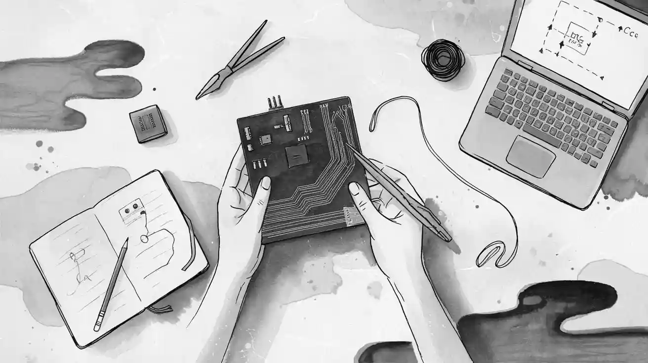
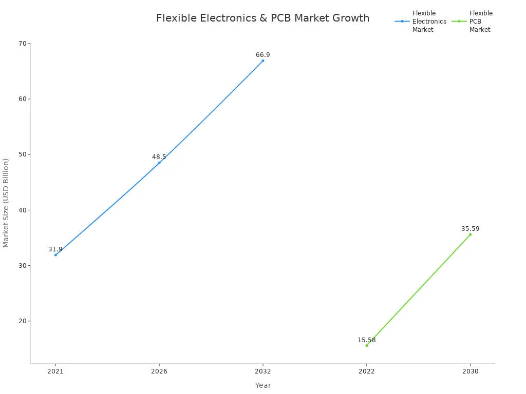
You can begin learning electronics with a soft pcb. It can bend and twist to fit many shapes. These pcb types help you build wearable devices and smartwatches. They also make robotics projects easier for beginners. Soft pcb projects are easy to try because they use simple tools. They also use easy-to-find materials. The need for flexible electronics is growing quickly, as you can see below:
Soft pcb solutions help make small and strong designs. These work for both gadgets and big machines.
Key Takeaways
- Soft PCBs can bend and twist to fit small spaces. They also fit curved spaces. This makes devices lighter. It also makes them more reliable.
- Pick soft PCBs for projects that need to bend. Use them if you want things to be light. They are good for tight spots. Wearables and smart gadgets often use them.
- Try beginner software like EasyEDA or KiCad to design your soft PCB. Plan your work carefully so you do not make mistakes.
- Get your design files ready. Think about using professional fabrication services. This can give you better quality and faster results.
- Join online groups and use tutorials to learn more. Practice and ask for help when building your flexible PCB projects.
What is a Soft PCB?

Features
A soft PCB is a printed circuit board made with bendable materials. You can twist or fold these boards to fit small spaces. This helps when you need electronics that are light and small.
Here is a table that shows what makes a soft PCB special:
| Aspect | Description |
|---|---|
| Definition | Soft PCBs are printed circuit boards made on soft insulating materials like polyimide films, polyester, polytetrafluoroethylene, or soft epoxy glass cloth. |
| Flexibility | You can bend or shape them to fit 3D spaces. They are good for wiring that needs to be packed tightly. |
| Layer Types | There are single-sided, double-sided, and multilayer soft PCBs. Each kind has a different number of conductor and cover layers. |
| Material Properties | Most use polyimide films because they handle heat and bend well. Copper is used for the main wires. |
| Classification Examples | There are single-sided, double-sided, multilayer, and rigid-flex PCBs. Rigid-flex has both flexible and stiff layers. |
| Applications | Used in airplanes, cars, and small electronic devices that must be dependable. |
Soft PCBs weigh less than hard ones. They can make a device up to 75% lighter. They also handle bumps and shaking better than regular boards. This is why they work well in things that move or get hit a lot.
Applications
Soft PCBs are used in many fields. In medicine, they power health monitors you can wear, like heart and blood pressure trackers. They are also found in machines like CT and ultrasound scanners. Doctors use them in infusion pumps and even inside pacemakers. Their flexibility helps these devices fit the body and follow safety rules.
In cars and planes, soft PCBs help run control systems. They save space and make things more reliable. You will also see them in smartwatches and foldable phones. Because they bend and fit in tight spots, they are important for new gadgets.
Tip: If your device needs to move or fit in a small spot, a soft PCB is usually the best pick.
Why Use Soft PCBs?
Advantages
Soft pcbs give you many good things. They can bend and twist to fit small or strange spaces. This is great for smart gadgets, foldable phones, and things you wear. Devices can be lighter and thinner because of special materials like polyimide. These materials stand up to sweat, heat, and rough use. Your device will last longer because of this.
Here are some main advantages:
- You can make smaller and more comfy devices for the body or tight spots.
- Flexible boards mean you need fewer connectors inside your device. Fewer connectors means fewer things can break.
- Your device works better because the pcb can handle shaking and bending.
- You save space and weight, which helps with portable electronics, drones, and medical tools.
- The flexible design lets the board move with the body and helps sensors work better.
Note: Flexible pcbs can cost more at first, but you save money later because you use fewer connectors and wires.
When to Choose
Pick a flexible pcb if your project needs to bend or fit in a small place. These boards are best for things that move a lot or must stay light. Wearable biosensors and medical tools use flexible boards because they must fit the body and last a long time. You also find them in cars, planes, and portable gadgets where space and weight are important.
Here is a table to help you know when to use a flexible pcb:
| Scenario | Why Choose Flexible PCB? |
|---|---|
| Space-Constrained Designs | Fits tight spaces and needs fewer connectors. |
| Weight-Sensitive | Makes things lighter, which helps in cars, planes, and wearables. |
| High Reliability | Handles shaking, bumps, and heat better than hard boards. |
| Custom Shapes | Bends and folds to fit special shapes or body parts. |
| Simplified Assembly | Makes building and connecting parts easier and saves time and money. |
Use a flexible pcb if your device must bend, move, or fit a special shape. Hard boards are good for flat and simple designs. Flexible boards give you more choices for cool and new projects.
Tools and Materials
PCB Design Software
To begin your soft PCB project, you need software. The right program lets you draw circuits and put parts in place. It also helps you check your design for mistakes. Many programs are easy for beginners to use. Some let you drag and drop parts to make things simple. Others have more tools for bigger or harder projects. Here is a table that lists popular programs and what makes them good for soft PCB work:
| Software | Key Features for Beginners and Soft PCBs |
|---|---|
| Upverter | Automated routing, BOM management, 3D models, easy documentation |
| PCBWeb | Multi-page schematics, design rule checking, copper pouring, Digi-Key parts catalog, simple library editor |
| LibrePCB | Intuitive interface, multi-layer support, live 3D viewer, design rule check |
| DipTrace | Easy interface, multi-sheet schematics, smart routing, wide import/export support |
| EasyEDA | Cloud-based, real-time collaboration, large component libraries, integrated fabrication |
| EAGLE | Basic schematics, single/double-sided PCBs, big component library, good for small projects |
| DesignSpark PCB | Unlimited schematic sheets, export to mechanical design, design rules checker |
| KiCad | Full schematic capture, industry-standard outputs, cross-platform, 3D viewer, open-source |
| Fritzing | User-friendly for DIY, auto and hand-routing, routing guidelines, Gerber export |
| Altium Designer | Large component library, 3D visualization, advanced routing, multi-sheet schematics, DRC and DFM outputs |
Tip: If you are just starting, try EasyEDA or KiCad. These programs have lots of guides and a big group of people who can help you learn.
Materials
You need special materials to build a soft PCB. The most important part is the flexible substrate. Polyimide is the best choice for most projects. It bends easily, stays strong, and can take high heat. You can solder parts on it many times and it will not break. Polyester is cheaper but cannot take much heat. Liquid Crystal Polymer is good if you need it to resist water, but it costs more.
Here is a table to help you see the main materials:
| Material | Temperature Resistance | Cost | Dielectric Constant | Moisture Resistance | Tensile Strength |
|---|---|---|---|---|---|
| Polyimide (PI) | High (-200 °C to 300 °C) | Inexpensive | 2.78 - 3.48 | Low | High |
| Polyester (PET) | Low | Inexpensive | 2.4 | Low | High |
| LCP | High | Expensive | 2.85 | High | High |
You also need copper foil to make the circuit lines. Coverlay films, made from Polyimide or Polyester, protect the circuit from damage. When you pick your materials, think about how hot your project will get and how much money you want to spend.
Note: Polyimide is the best choice for most soft PCB projects. It gives you strength, bends well, and can take heat.
PCB Design Process
Making a soft PCB needs careful steps. You must plan for bending. Pick the best materials for your project. Use special software tools to help you. Each step helps you build a board that bends and lasts.
Planning
Start with a good plan for your pcb. Good planning keeps your board strong and bendy. Here are the main things to do:
- Choose the right base material. Polyimide is best for most projects. It bends, handles heat, and lasts long. Polyester is good for simple boards.
- Use strong glue and copper. These hold the layers together. They also help with heat when the board bends.
- Draw your pcb with smooth lines. Keep parts away from places that will bend. This stops damage and stress.
- Plan where power and ground lines go. A good layout keeps current moving and stops overheating.
- Test your design early. Use computer tools to find problems before building.
- Think about where your board will be used. Pick materials that can handle heat, water, and pressure.
- For flex-rigid boards, balance stiff and bendy layers. This gives you both support and flexibility.
Tip: Testing early with computer tools saves time and money.
Schematic
A clear schematic makes your pcb easy to build. Follow these tips for good schematics:
| Best Practice | Explanation | Benefit |
|---|---|---|
| Clear Planning | Make a plan before you start drawing. | Saves time and stops mistakes. |
| Predefined Templates | Use ready-made parts and layouts. | Makes your work faster and keeps things the same. |
| Version Control | Use programs like Git to track changes. | Stops errors from people working together. |
| Minimize trace lengths | Keep lines short to stop signal loss. | Signals stay strong and clear. |
| Use ground planes | Use a big ground area for steady signals. | Less noise and better working board. |
| Separate power and signals | Keep power lines away from signal lines. | Stops signals from getting mixed up. |
Keep part shapes and symbols the same. This helps parts fit and stops build problems. Use standard libraries for correct shapes and pins. Check your schematic with friends or computer tools. Label all parts and wires clearly. Follow rules like IPC to make your board work everywhere.
Layout
The layout is where your pcb design becomes real. Soft PCB layouts need extra care. Remember these points:
- Mark where the board is bendy or stiff. This helps you place parts right.
- Put heavy or hot parts on stiff areas. These spots give support and help with heat.
- Only put bendy parts on flexible areas.
- Draw lines with smooth curves and some extra length. This lets the board bend without breaking.
- Place parts in line with the bendy direction. This lowers stress when bending.
- Leave space around bendy spots. Follow the smallest bend size to stop damage.
- Always think about stress and bend size. This keeps your board working well.
Note: Some software helps with these layout needs. Look for tools with bend checks, 3D views, and material choices.
Best Practices
You can make designing easier with the right software. New tools have many helpful features:
- Use ready-made templates for flexible boards. These save time and lower mistakes.
- Pick software that is easy to use and has guides. This helps you learn faster.
- Test your design in the program before building. Find and fix mistakes early.
- Try 3D views to see your board from all sides. This helps you spot stress points.
- Use tools that let you design both flexible and stiff boards. These help you mix both in one project.
- Use bend calculators to warn if you bend too much.
- Check for build rules. Good software warns you if you break any rules.
- Connect your pcb design with case design tools. This helps your board fit in cases or wearables.
| Software Feature | Description and Importance |
|---|---|
| Support for Flex and Rigid-Flex | Lets you design boards with both stiff and bendy parts. |
| Bend Radius Calculation Tools | Warns you if you bend the board too far. |
| Material Library and Selection | Helps you pick the best bendy materials. |
| 3D Visualization and Simulation | Shows how your board will look and bend before building. |
| Manufacturing Output and DFM Checks | Makes sure your design is ready for the factory. |
| Integration with Mechanical CAD | Matches your board with cases for a perfect fit. |
| Automated Routing for Flex Areas | Draws lines in bendy zones to keep signals strong. |
| Multi-Zone Layer Management | Handles different bendy and stiff zones in one board. |
| Impedance Control | Keeps signals clear in fast circuits. |
| Design Violation Warnings | Alerts you to problems before you build the board. |
Remember: The right software makes designing easier and helps you avoid mistakes.
Soft PCB Fabrication
Preparing Files
You need to get your design files ready before making your pcb. Getting files ready helps you avoid mistakes and work faster. Most companies want Gerber files. These files show each board layer, like copper lines, solder mask, and silkscreen. You also need drill files, board outlines, and sometimes drawings for making many boards at once.
Here is a checklist of what files you need:
- Gerber files for every layer (top, bottom, inside)
- Solder mask and silkscreen layers
- Drill files (Excellon or IPC-NC-349)
- Board outline and mechanical layers
- Panelization drawings if you want more than one board
- Optional: stack-up diagrams, netlists, and 3D assembly models
Some companies use IPC-2581 or ODB++ files. These files put all your design, making, and building info together. If your board is simple, Gerber files are best. For harder or thicker boards, use IPC-2581 or ODB++.
Always check your files before you send them. Follow these steps to make sure your files are good:
- Check your files with a Gerber viewer or other tools. This helps you find mistakes before you send them.
- Run a Design Rule Check (DRC) in your software. This checks if your design matches the company’s rules.
- Check your Bill of Materials (BOM) and Pick-and-Place files. Make sure the parts list and placement are the same.
- Look at your Gerber files to check if layers line up and details are right.
- Use online platforms to send files. These help you share, work together, and keep track of changes.
- Talk to your company. Ask about file types and size limits.
- Give clear drawings for where parts go and how to solder them.
Tip: Checking your files twice saves time and money when making your pcb.
Fabrication Methods
You can make pcbs at home or use a company. Each way has its own steps and tools.
DIY Fabrication
If you want to make a soft PCB at home, be gentle with the flexible base. Here are the main steps:
- Design and Layout: Plan your circuit with the right bend and line width. Keep parts away from places that will bend.
- Lamination and Layering: Stick copper foil to the flexible base with special glue. Make sure the layers match up well.
- Etching and Patterning: Use chemicals or a laser to take away extra copper. This makes your circuit paths.
- Cutting and Shaping: Cut the board to the right shape. Round corners and smooth edges so it bends better.
Work in a clean place and wear gloves to protect the base. Keep your boards flat in antistatic bags. Do not bend the board before you put on parts to keep it strong.
Professional Fabrication Services
Many beginners use companies like JLCPCB or PCBWay to make pcbs. These companies have good machines and check quality. You upload your files, pick your materials, and choose things like board thickness and finish.
Professional companies give you:
- Very good detail for small lines and parts
- Better checks and testing
- Fast making times
- Choices for thick and flex-rigid boards
You still need to get your files ready. Most companies have online tools to check your files before you order.
Note: Using a company to make your pcb saves time and gives better results, especially for hard or wearable projects.
Assembly Tips
Putting together a soft PCB needs gentle care. Flexible boards can rip or bend wrong if you are rough. Use these tips for easy assembly:
- Use gentle pick-and-place machines to put on parts. This keeps the base safe.
- Put stiffeners under heavy or tiny parts. Stiffeners help hold the board and stop stress.
- Use fiducial markers to line up parts. This helps you place parts right.
- Solder with careful heat. Use reflow soldering with a soft heat curve. Low-heat solder is best for soft materials.
- Hold the board flat with heat-safe holders when soldering. This stops the board from bending.
- Check your board after you finish. Use machines to look for mistakes. Test if the board bends and if power flows right.
| Step | What to Do | Why It Matters |
|---|---|---|
| Component Placement | Use gentle pressure and stiffeners | Stops damage and keeps parts straight |
| Soldering | Watch the heat and keep board flat | Stops bending and mistakes |
| Inspection | Look closely and test bending | Makes sure it works and lasts |
Remember: Take your time when putting your board together. Careful work and testing help your soft PCB last longer and work better.
Troubleshooting
Common Mistakes
When you work on a soft PCB, you can make mistakes. Knowing about these mistakes helps you do better next time.
- Sometimes, people forget to add a ground plane. This can make signals weak or noisy.
- If you skip checking clearances, your board might short out.
- Not using decoupling capacitors can mess up the power supply.
- If you do not label parts, you might get mixed up later.
- Skipping design rule checks in your software causes hard-to-fix errors.
- If you do not get the right layer stackup, your board may not work.
- Picking the wrong copper weight can limit how much current flows.
- Bad trace placement can cause electromagnetic problems.
- Putting parts in the wrong place makes assembly tough and can cause heat issues.
- If you do not test or make a prototype, your project might fail.
- Weak power lines can make voltage drop and hurt performance.
- If you do not write down your design, fixing or upgrading is harder.
Tip: Always use your software’s checks and talk to your fabricator early.
Solutions
You can fix many soft PCB problems if you are careful. If you see a cracked trace, clean it with isopropyl alcohol and a soft brush. Gently scrape off the solder mask with a small blade to show the copper. Use conductive glue or solder a thin wire to fix the break. Make sure the fix follows the same path as before to keep signals strong. Cover the fix with UV epoxy or kapton tape to stop shorts.
If your board layers come apart, heat the spot with a heat gun at 150°C. This makes the glue soft but does not hurt the polyimide. Put epoxy glue between the layers with a small syringe. Spread it out, clamp it gently, and let it dry for 24 hours.
After any fix, test your flexible PCB to see if it works. Use the right tools and watch the temperature so you do not cause more damage. Careful repairs and testing help your soft PCB last longer and work better.
Remember: Careful fixes and regular tests keep your soft PCB safe and strong.
Resources
Tutorials
You can find many trusted online places to learn soft PCB design and fabrication. EasyEDA lets you design circuits for free. You can also test your circuits and order boards there. Their tutorials show you each step, like drawing a schematic and looking at your board in 3D. You get real-time parts libraries and tools to manage your projects. This helps you start and finish your first flexible PCB project easily.
Altium Education gives beginners a full learning path. You can use a free student license to try Altium Designer, which is a top tool in the industry. Their lessons teach you everything from simple schematics to making boards in factories. You do hands-on projects and get certificates when you finish. This helps you learn skills and get ready for harder designs.
Tip: Try beginner tutorials and make small projects to practice. You will learn more by doing things yourself.
Communities
You can join online groups to get help and share your work. Many forums and groups talk about flexible PCB and bendable electronics. Here are some good places:
- EasyEDA Community Forum: Ask questions and show your designs.
- Reddit r/PrintedCircuitBoard: Get advice, ideas, and help with problems.
- All About Circuits: Talk about soft PCB design and fabrication.
- Hackaday.io: Share your projects and get tips from other makers.
These groups help you fix problems and keep you excited. You can also look for local maker spaces or electronics clubs for help in person.
Suppliers
You need good suppliers for flexible PCB materials and making boards. The table below lists top companies for hobbyists and professionals:
| Supplier | Materials Offered | Key Features and Services | Pricing (USD/sq in) | Lead Time (Days) | Min. Order | Notes |
|---|---|---|---|---|---|---|
| PCBWay | Flexible PCBs, FR-4, Aluminum | Flexible and HDI PCBs, assembly, good price-quality balance | $3 - $6 | 3-7 | 5 boards | Great for complex and custom projects |
| BESTFPC | Flexible PCBs, FR-4, Aluminum | Fast turnaround, low cost, easy online ordering | $2 - $5 | 3-7 | 5 boards | Popular for quick and affordable fabrication |
| DigiKey Red | FR-4 | Component sourcing, PCB fabrication, rapid prototyping | $7 - $12 | 10-14 | 1 board | One-stop shop for parts and boards |
| Aisler | FR-4 | High quality, user-friendly, shared panel service | $6 - $10 | 7-10 | 1 board | Good for small batches and precision |
| Bittele Electronics | Flexible PCBs, FR-4, Aluminum | Assembly, turn-key solutions, testing | $4 - $8 | 5-10 | 1 board | Offers assembly and testing services |
| OSH Park | FR-4 | US-based, shared panel production | $5 - $10 | 12-15 | 3 boards | High quality, mainly FR-4 boards |
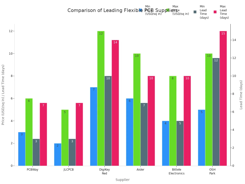
Note: Check prices, wait times, and services before you buy. This helps you choose the best supplier for your soft PCB project.


.png)
.png)
.png)
.png)

.png)

