


 2025-07-28
 BEST
BEST
When I select a Car Flex PCB for automotive electronics, I focus on reliability above all else. I have seen how harsh environments can cause failures. The most common issues I notice include:
- Mechanical stress from bending leads to micro-cracks in traces.
- Thermal expansion mismatch causes stress at connections.
- Improper assembly can damage circuits.
- Temperature changes and humidity affect stability.
Choosing the right materials and design helps me avoid these problems and ensures lasting performance.
Key Takeaways
- Choose materials like polyimide that handle heat, chemicals, and bending to ensure long-lasting performance in harsh car environments.
- Design flex PCBs with proper bend radii, avoid sharp bends, and place components away from flex zones to prevent mechanical damage.
- Test your flex PCBs thoroughly for vibration, thermal shock, and electrical performance to catch problems before production.
- Work with manufacturers who have automotive certifications and offer strong technical support and customization options.
- Use a detailed checklist covering application needs, materials, design, manufacturing, testing, and quality control to build reliable car electronics.
Application Needs
Function Requirements
When I choose a Car Flex PCB for automotive electronics, I always start by listing the main functions it must support. In my experience, these boards must handle much more than simple connections. They need to deliver high performance and reliability, especially in systems like infotainment, ADAS, and powertrain controls. Here are the main requirements I look for:
- High current and voltage handling, especially for powertrain and battery systems.
- Strong thermal management, using heat sinks or thermal vias to move heat away from sensitive parts.
- Resistance to vibration and mechanical stress, which means using reinforced structures and durable adhesives.
- Excellent electromagnetic compatibility, with shielding and ground planes to prevent interference.
- Advanced design features, such as multi-layer or rigid-flex construction, to fit complex circuits into small spaces.
- Compliance with strict automotive standards for safety and reliability.
I always check that the flex PCB meets these needs before moving forward.
Environment & Stress
Automotive environments can be harsh. I have seen how temperature swings, humidity, and constant vibration can damage electronics. To make sure my designs last, I pay close attention to these factors:
| Environmental Stress | Typical Range / Conditions | Impact on Automotive Flex PCBs | Testing Standards / Methods |
|---|---|---|---|
| Temperature | -40°C to 85°C (operating), -55°C to 125°C (thermal shock) | Thermal expansion, solder cracks, delamination | IPC-TM-650, HALT, ALT |
| Humidity | Up to 85% RH | Corrosion, material breakdown | ALT (1000 hours at 85% RH) |
| Vibration | 5 Hz to 2000 Hz, up to 20 G | Cracked joints, broken traces | MIL-STD-810, ISO 16750-3 |
I always select materials that resist corrosion and match thermal expansion rates. I also make sure connectors can survive at least 100,000 flex cycles.
Space & Flexibility
Space is always tight in cars. I need my flex PCBs to bend and fit into small, odd-shaped areas. I follow these guidelines:
- For single-layer flex, I use a minimum bend radius of 6 times the material thickness.
- For two-layer flex, I use 12 times the thickness.
- For four or more layers, I use 24 times the thickness.
I avoid placing components or vias in bend zones. I also choose polyimide materials for their flexibility and thermal stability. Smooth curves, not sharp bends, help prevent cracks and keep the board working longer.
Car Flex PCB Selection Criteria
Material Choice
When I select materials for a Car Flex PCB, I always start with the substrate. Polyimide films are my top choice because they offer excellent flexibility and can handle high temperatures. Most automotive applications require materials that work from -40°C up to 150°C, but some parts of the car, like under the hood, need even higher temperature resistance. For those, I use DuPont Pyralux® all-polyimide, which can operate above 250°C. This gives me confidence that the board will not fail in extreme heat.
I also pay attention to adhesives. Acrylic-based adhesives work well for thermal cycling between -40°C and 125°C. For rigid sections, I use FR-4 epoxy glass, which has a glass transition temperature between 130°C and 180°C. I always check that the materials meet IPC-4203 standards for quality and reliability.
| Material Type | Application Section | Temperature Rating Range |
|---|---|---|
| Polyimide Films | Flexible sections in flex PCBs | -40°C to 150°C (automotive typical), up to 200°C general flex use |
| FR-4 Epoxy Glass | Rigid sections in rigid-flex PCBs | 130°C to 180°C (glass transition temperature) |
| Acrylic-based Adhesives | Bonding layers in flex PCBs | -40°C to 125°C (thermal cycling resistance) |
| DuPont Pyralux® All-Polyimide | High-temperature flex circuits | >250°C (specialized automotive/high-temp use) |
Tip: I always match the material’s temperature rating to the specific area of the car where the PCB will be used. This helps prevent failures from overheating or thermal shock.
Layer & Design
The number of layers and the design layout play a big role in how well a Car Flex PCB performs. For simple circuits, I use single-layer designs. When I need to fit more functions into a small space, I choose multi-layer or rigid-flex designs. This lets me route signals efficiently and add ground planes for better electromagnetic compatibility.
I follow these best practices for layout and stack-up:
- I use uniform dielectric layers and control the spacing between traces and ground planes.
- I avoid sharp 90° bends and keep bend radii large to reduce mechanical stress.
- I minimize the number of vias, since each via can cause impedance changes and signal loss.
- I use simulation tools to check impedance and signal integrity before finalizing the design.
Here are some layout tips I always follow:
- Use low dielectric constant materials for high-speed signals.
- Control trace width and spacing to achieve the target impedance.
- Validate impedance in production using Time-Domain Reflectometry (TDR).
Thermal & Chemical Resistance
Automotive environments expose PCBs to heat, oil, and chemicals. I always choose polyimide because it resists both high temperatures and harsh chemicals. Polyimide can handle short bursts up to 400°C and resists solvents and oils. This makes it perfect for under-hood or powertrain applications.
| Material | Thermal Stability (°C) | Chemical Resistance | Flexibility and Durability | Typical Applications |
|---|---|---|---|---|
| Polyimide (PI) | Up to 400°C (short bursts) | Excellent resistance to solvents and oils | Endures over 100,000 bending cycles, highly flexible and durable | Automotive, aerospace, industrial (harsh environments) |
| PET | Up to 150°C (continuous) | Lower chemical resistance | Less durable, suitable for static or low-bend uses | Consumer electronics, keypads |
| PEN | Around 120-180°C (glass transition) | Moderate chemical resistance | Less flexible and durable than PI | Automotive sensors, moderate heat applications |
| LCP | Up to 300°C (continuous) | Good chemical resistance, low moisture absorption | Good flexibility but more expensive, less common in automotive flex PCBs | RF, microwave, 5G devices |
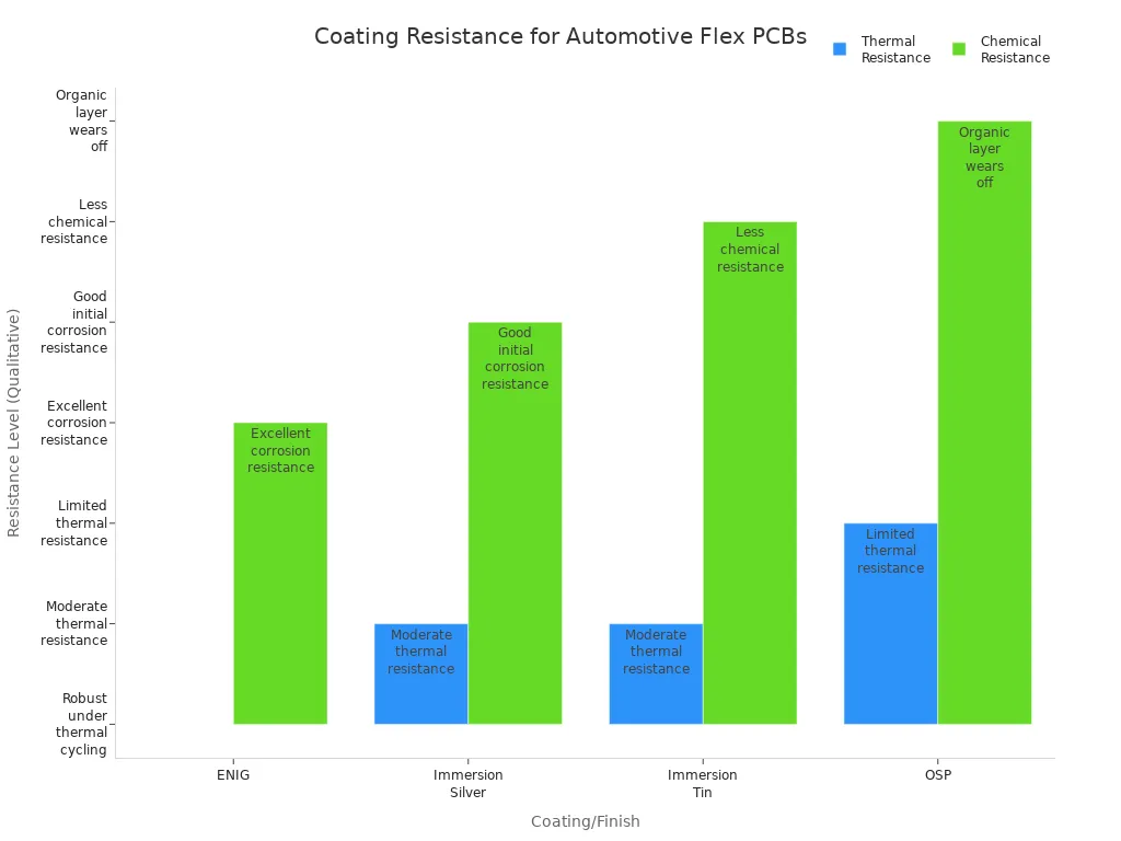
I also use coatings and adhesives to boost resistance. Electroless Nickel Immersion Gold (ENIG) is my preferred surface finish because it stands up to corrosion and thermal cycling. For extra protection, I use advanced epoxy potting compounds and N-Phenylmaleimide (NPMI)-based adhesives. These materials increase the board’s resistance to heat and chemicals, making sure the Car Flex PCB lasts longer.
Note: I always check that the materials and coatings meet UL94-V0 flame retardancy and ISO/IPC standards for automotive use.
Vibration & Durability
Cars create constant vibration and sudden shocks. I make sure my Car Flex PCB can survive these stresses by choosing tough materials and testing them thoroughly. Polyimide stands out because it can handle over 100,000 bending cycles without cracking. I also use reinforced adhesives and stiffeners in high-stress areas.
I test my designs using industry standards like MIL-STD-810 and ISO 16750-3. These tests simulate real-world conditions, such as:
- Vibration from 5 Hz to 2,000 Hz at up to 20 G acceleration.
- Thermal shock cycling from -55°C to 125°C.
- Highly Accelerated Life Testing (HALT) to find weak points before production.
| Test Type | Frequency / Temperature Range | Acceleration / Duration | Standards Referenced | Purpose / Notes |
|---|---|---|---|---|
| Vibration Testing | 5 Hz to 2,000 Hz | Up to 20 G (standard), 50 G (HALT); e.g., 10 G for 8 hours | MIL-STD-810, ISO 16750-3 | Simulates road vibrations to detect mechanical failures like cracked solder joints or broken traces. |
| Thermal Shock | -55°C to 125°C | 100-500 cycles, rapid transitions (<10 seconds) | IPC-TM-650 | Tests resistance to rapid temperature changes causing thermal expansion stresses. |
| HALT (Highly Accelerated Life Testing) | -100°C to 200°C (temperature), vibration up to 50 G | Extreme conditions to failure | Internal HALT protocols based on above standards | Identifies design weaknesses during design phase by pushing boards beyond normal limits. |
| HASS (Highly Accelerated Stress Screening) | Based on HALT results, e.g., 120°C and 20 G vibration | ~30 minutes per test | Internal production screening protocols | Screens production units for defects ensuring reliability. |
Alert: I never skip vibration and thermal shock tests. These tests help me catch problems before the PCB goes into a car.
Electrical Performance
Electrical performance is critical for every Car Flex PCB I design. I focus on signal integrity, current carrying capacity, and noise immunity. High-speed automotive systems use advanced data transmission methods, so I use controlled impedance traces and robust connectors to keep signals clean.
I balance trace width to support enough current without causing impedance mismatches. For example, a 0.3 mm trace on FR-4 achieves about 50-ohm impedance, which is ideal for many automotive signals. I use simulation tools and test equipment like oscilloscopes and vector network analyzers to check for reflections, crosstalk, and data errors.
Here are the key steps I follow:
- I test current carrying capacity by applying different loads and checking for overheating.
- I measure noise levels to make sure they stay within safe limits.
- I validate signal integrity using eye diagrams and bit error rate testers.
- I follow IPC-6013 standards for electrical and mechanical testing, including flex endurance and environmental resistance.
Pro Tip: I always use test coupons that match the actual PCB stack-up to ensure accurate impedance and signal integrity measurements.
Manufacturer Evaluation
Certifications & Standards
When I choose a manufacturer for automotive flex PCBs, I always check their certifications and standards. These certifications show that the manufacturer follows strict rules for quality, safety, and environmental care. I look for the following:
| Certification / Standard | Description |
|---|---|
| ISO 14001:2015 | Environmental management system certification ensuring sustainable manufacturing practices. |
| ISO 9001:2015 | Quality management system certification ensuring consistent product quality. |
| IATF 16949:2016 | Automotive industry-specific quality management system standard. |
| UL Mark | Safety certification for electrical components. |
| RoHS | Restriction of hazardous substances compliance for environmental safety. |
| GB | Chinese national standards applied in manufacturing. |
| IPC-650 | Standard for printed board testing and inspection. |
| IPC-6012 | Qualification and performance specification for rigid PCBs. |
| IPC-6013II / IPC-6013III | Qualification and acceptance criteria for flexible circuits, including automotive flex PCBs. |
I always make sure the manufacturer meets IATF 16949 and IPC-6013 standards. These prove that the company can deliver reliable and safe products for cars. I also check if they use strong testing methods like in-circuit testing, functional testing, and environmental stress testing. These tests help catch problems early and ensure the flex PCBs work well in real-world conditions.
Customization
Every car model has unique needs, so I look for manufacturers who offer a wide range of customization options. I often request polyimide as the base material because it handles heat and chemicals well. For the copper traces, I prefer rolled annealed copper foil since it bends without cracking. I also ask for custom shapes to fit tight spaces inside vehicles.
- I make sure the bend radius matches the application, especially for parts that move or flex often.
- I work with the manufacturer to place heavy components in areas that do not bend much.
- I often add stiffeners, like polyimide or FR4, to support connectors and large parts. This helps the board survive vibration and keeps everything stable.
Testing prototypes under real conditions is a must for me. I want to see that the custom design can handle the stress of daily driving.
Support
Strong technical support from the manufacturer makes my projects much smoother. I value companies that offer expert engineering help, such as design reviews and advice on manufacturability. When I work with a good partner, they help me solve problems with vibration, humidity, and heat. They also guide me through compliance with automotive standards and provide services like prototyping, assembly, and testing.
Tip: I always choose manufacturers who keep communication open and provide clear documentation. This helps me avoid delays and ensures my designs meet all requirements.
Manufacturers who offer ongoing support and quick feedback help me finish projects faster and with fewer risks. Their experience with automotive flex PCBs gives me confidence that my designs will work reliably in the field.
Mistakes to Avoid
Ignoring Environment
I have learned that ignoring the environment where the PCB will operate leads to early failures. Temperature swings, humidity, and exposure to chemicals can damage even the best-designed boards. I always check the operating temperature range and humidity levels for each application. For example, under-hood electronics face much higher heat and vibration than dashboard controls. I select materials and coatings that resist corrosion and thermal shock. I also make sure to review the placement of the PCB to avoid areas with direct exposure to oil or water.
Tip: Always match the material and design to the harshest conditions the board will face. This step prevents costly replacements and keeps the system running safely.
Overlooking Reliability
Reliability is not just about using strong materials. I focus on how the board will perform over time. Vibration, repeated bending, and thermal cycling can cause micro-cracks or solder joint failures. I reinforce high-stress areas with stiffeners and use adhesives that can handle temperature changes. I also check that the design meets automotive standards for durability. Skipping these steps can lead to breakdowns that are hard to diagnose and expensive to fix.
- I always ask myself: Will this board survive 100,000 flex cycles?
- I test for vibration and thermal shock before approving a design.
Skipping Validation
Skipping validation is one of the biggest mistakes I see. I follow a strict process to make sure every board meets quality and safety standards before mass production. Here are the steps I use:
- I check that the design follows ISO 26262, IPC-A-600, and AEC-Q100 standards.
- I run functional tests that simulate real-world conditions, such as sensor input and response time.
- I perform environmental tests, including temperature cycling and humidity exposure.
- I use accelerated life testing to predict long-term reliability.
- I measure signal integrity and EMI in controlled environments.
- I test for mechanical strength with vibration and shock tests.
- I design for testability by adding test points and connectors.
- I use automated inspections to catch defects early.
- I repeat tests at every stage, from prototype to post-assembly.
- I keep detailed records of all tests and results.
- I optimize the stack-up and material selection for each application.
- I work closely with my team to address any issues quickly.
Skipping even one of these steps can lead to failures in the field. I always validate thoroughly to ensure long-term success.
Car Flex PCB Checklist
When I work on a Car Flex PCB project, I always rely on a detailed checklist. This approach helps me avoid mistakes and ensures every step meets strict automotive standards. I have learned that a checklist keeps my process organized and reduces the risk of missing important details.
Here is the checklist I use for every Car Flex PCB:
Define Application Needs
I start by listing all the functions the PCB must support. I check the operating environment, including temperature, humidity, and vibration levels.
Select Proper Materials
I choose materials that match the temperature range and chemical exposure of the application. Polyimide is my go-to for flexibility and heat resistance.
Review Design and Layout
I verify the number of layers, bend radius, and placement of components. I avoid sharp bends and keep critical traces away from flex zones.
Confirm Manufacturing Tolerances
I check that the manufacturer can meet the required tolerances for trace width, spacing, and hole size.
Prepare a Complete Bill of Materials (BOM)
I make sure all part numbers, footprints, and quantities are correct. This step prevents delays and assembly errors.
Validate Assembly Process
I confirm the use of precise SMT stencils and proper solder paste application. I check that component placement matches the design files.
Test for Electrical and Mechanical Performance
I run tests for signal integrity, current capacity, and resistance to vibration and thermal shock.
Inspect Quality Control Measures
I review inspection reports for misalignment, insufficient solder, or material issues. Early detection helps me fix problems before production.
Using this checklist gives me confidence that my Car Flex PCB will perform reliably in any automotive environment. I recommend following a similar list for every project.
Selecting the right Car Flex PCB means following a clear process:
- Choose materials like polyimide and FR4 for durability and flexibility.
- Design with wide copper traces and avoid vias in bend zones.
- Test for heat, vibration, and signal integrity.
- Work with skilled manufacturers who follow strict standards.
I always use my checklist to catch every detail. Smart choices now lead to reliable, eco-friendly automotive electronics that last.
.png)
.png)
.png)
.png)

.png)

