


 2026-11-04

 BEST
A rigid-flex PCB for automotive applications must fit compact electronic modules while maintaining reliable connections under temperature changes, vibration, and mechanical stress. Incorrect stackups, tight bends, or poorly supported transitions can cause failures even when the initial electrical test passes.
This guide covers automotive applications, stackup selection, bend rules, and reliability verification, helping engineers make informed decisions before PCB manufacturing.
Where Are Rigid-Flex PCBs Used in Automotive Electronics?
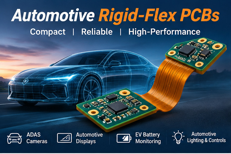
Rigid-flex PCBs are used in automotive modules where rigid component-mounting sections require flexible interconnections within limited installation space.
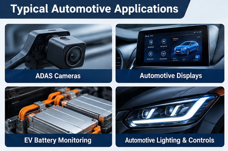
Common applications include:
-
ADAS Cameras: Connect image sensors, processing circuits, and interface boards inside compact camera housings. High-speed signal routing and controlled impedance are important design requirements.
-
Automotive Displays: Connect display controllers and interface circuits positioned at different angles inside dashboard assemblies.
-
Automotive Sensor Modules: Integrate sensing elements, signal-conditioning circuits, and control electronics where a conventional flat PCB cannot fit.
-
EV Battery Monitoring: Support compact monitoring modules requiring integrated rigid and flexible sections. Distributed cell-sensing connections may be better served by conventional FPC.
-
Automotive Lighting and Controls: Connect switches, sensors, and control circuits inside irregular enclosures where separate connectors occupy valuable space.
The right application is one where integrated rigid and flexible sections solve a specific mechanical or interconnection problem.
When Should Automotive Electronics Use Rigid-Flex Instead of Rigid PCB or FPC?
Choose rigid-flex PCB when the design requires integrated component support and flexible connections. Conventional PCB structures remain suitable when separate connectors already meet the installation and reliability requirements.
| Design Factor | Rigid PCB + Connectors | FPC + Connectors | Rigid-Flex PCB |
|---|---|---|---|
| Component support | Separate rigid boards | Reinforcement where needed | Integrated rigid sections |
| Installation geometry | Connectors or cables | Flexible interconnections | Integrated folded structure |
| Connector requirements | Usually required | Required between separate boards | Can eliminate selected connectors |
| Assembly | Multiple board connections | Connector and reinforcement handling | Integrated assembly |
| Best suited for | Modular electronics | Thin, distributed connections | Compact three-dimensional modules |
For automotive applications that need only a thin interconnection without integrated rigid circuitry, flexible PCB for automotive applications may be a simpler solution.
Which Rigid-Flex PCB Stackups Are Suitable for Automotive Applications?
Automotive rigid-flex PCB stackups should match routing density, signal integrity, and mechanical requirements. The number of copper layers extending through the flexible section is particularly important.
| Stackup Example | Rigid Layers | Flex Layers | Suitable Design Requirements |
|---|---|---|---|
| 4-Layer Rigid-Flex PCB | 4 | 2 | Compact sensors and moderate-density circuits |
| 6-Layer Rigid-Flex PCB | 6 | 2 | Higher-density routing and additional reference layers |
| 8-Layer Rigid-Flex PCB | 8 | 2 | Complex interfaces and multilayer control circuits |
These are example configurations, not mandatory automotive stackups.
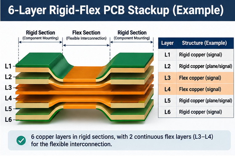
A typical 6-layer rigid-flex PCB can use four rigid-only copper layers and two continuous flexible layers:
-
L1–L2: Rigid-only copper layers for component connections and circuit routing.
-
L3–L4: Continuous flexible copper layers connecting the rigid sections.
-
L5–L6: Additional rigid-only copper layers for routing, power, or reference-plane functions.
The functions of individual layers must be assigned according to the circuit design.
This construction provides six copper layers in the rigid sections while keeping the flexible interconnection to two copper layers.
Before approving the stackup, verify:
-
Layer Arrangement: Identify which copper layers continue through each flexible region.
-
Rigid and Flex Thickness: Confirm compatibility with the enclosure and bending requirements.
-
Signal Reference Paths: Maintain suitable return paths for high-speed and controlled-impedance signals.
-
Copper and Dielectric Construction: Match the materials to electrical and mechanical requirements.
-
Transition Geometry: Define how rigid materials terminate at the flexible connection.
A higher layer count does not automatically improve reliability. The preferred construction meets the circuit requirements without unnecessary thickness or mechanical complexity.
How Should Materials Be Selected for Automotive Rigid-Flex PCBs?
Material selection depends on operating temperature, bending requirements, electrical performance, and assembly conditions. The substrate, copper, coverlay, and bonding system must function as a compatible construction.
-
Polyimide (PI): Commonly used for flexible substrates because of its thermal stability and flexibility. Thickness and material grade depend on the application.
-
Rigid Laminates: FR-4 or other suitable laminates provide component support. Thermal expansion and compatibility with the flexible core must be evaluated.
-
Rolled Annealed (RA) Copper: Often considered for repeated bending because of its ductility. The selected copper grade and complete construction still determine fatigue performance.
-
Electrodeposited (ED) Copper: May be suitable for static-bend applications when the material meets the mechanical requirements.
-
Adhesiveless Flexible Laminates: Can reduce flexible-core thickness by eliminating a separate copper-to-polyimide adhesive layer.
-
Polyimide Coverlay: Protects exposed flexible circuitry. Its thickness and adhesive properties must suit the manufacturing and assembly process.
For automotive projects, material specifications should remain controlled between prototype approval and production. Substitutions affecting electrical or mechanical performance require engineering review.
What Are the Critical Bend Design Rules for Automotive Rigid-Flex PCBs?
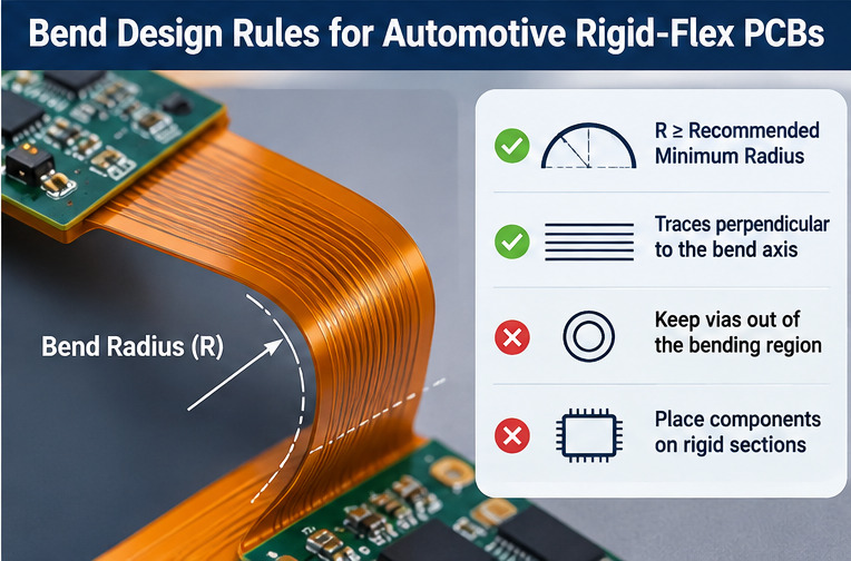
Reliable bending depends on the flexible construction, bend radius, and final installed geometry. A bend radius suitable for one stackup may damage another.
The following rules should be established before fabrication:
-
Static vs. Dynamic Bending: Static bends are formed during installation and remain fixed. Dynamic bends involve repeated movement and require a construction qualified for cyclic strain.
-
Bend Radius: Determine the minimum radius from the complete flexible stackup, copper thickness, conductor layers, and intended movement. Avoid applying one fixed thickness multiplier to every design.
-
Flexible Length: Provide enough length to achieve the required bend angle without exceeding the construction's bending limits.
-
Rigid-to-Flex Transition: Avoid concentrating bending loads directly at the stiffness transition. Provide appropriate strain relief and mechanical support.
-
Installed Geometry: Define the bend location, direction, angle, and final shape in the mechanical drawing.
IPC-2223F provides design guidance for flexible and rigid-flex printed boards. Final bending requirements should also follow the selected material specifications and actual mechanical conditions.
How Should Traces, Vias, and Components Be Placed in Automotive Rigid-Flex PCBs?
Automotive rigid-flex PCB layout must maintain electrical performance while keeping sensitive circuit features away from mechanically stressed regions.
Key layout rules include:
-
Trace Direction: Route conductors approximately perpendicular to the bend axis, following the bending direction. Use smooth transitions rather than sharp corners.
-
Trace Arrangement: Consider staggered conductors in multilayer flexible regions to reduce unnecessary copper concentration at the same bending location.
-
Via Placement: Keep plated through-holes and other vias outside designated bending regions. Place layer transitions in mechanically suitable locations.
-
Component Placement: Mount components on rigid or appropriately supported sections, with adequate clearance from mechanical boundaries.
-
Copper Distribution: Avoid unnecessary solid copper areas in bending regions. Modified copper patterns must still meet electrical requirements.
-
Controlled Impedance: Account for dielectric and reference-plane changes between rigid and flexible regions, particularly for high-speed camera interfaces.
Mechanical layout and electrical performance must be verified together. A flexible connection that fits the enclosure is unsuitable if its routing compromises signal integrity.
What Causes Automotive Rigid-Flex PCB Failures Under Heat and Vibration?
Automotive rigid-flex PCB failures commonly involve conductor fatigue, thermal expansion, interconnection damage, or mechanical loading from the enclosure.
Typical failure mechanisms include:
-
Copper Trace Cracking: Repeated strain can cause intermittent or permanent open circuits. Investigate the fracture location and actual movement conditions.
-
Rigid-to-Flex Transition Damage: Concentrated mechanical loads may cause conductor cracks or protective-layer separation. Examine the transition and surrounding supports.
-
Interlayer Delamination: Thermal expansion mismatch or inadequate adhesion can cause material separation during thermal exposure.
-
Plated-Hole Failure: Temperature cycling may expose weaknesses in plated-hole structures. Microsection analysis can help determine the cause.
-
Solder Joint Fatigue: Vibration and insufficient mechanical support may transfer loads into solder connections.
Similar electrical failures can have different root causes. Electrical inspection, microsection analysis, and mechanical examination may be needed before selecting corrective actions.
How Can Automotive Rigid-Flex PCB Reliability Be Tested and Verified?
Reliability verification should combine bare-board inspection with testing based on the intended automotive environment. Test conditions and acceptance criteria must be defined before qualification.
-
Electrical Testing: Checks continuity and isolation before assembly and, when required, after environmental exposure.
-
Microsection Inspection: Evaluates plated-hole integrity, dielectric separation, copper structures, and critical rigid-to-flex areas.
-
Thermal Cycling: Assesses the effects of repeated temperature changes on electrical connections and structural integrity.
-
Vibration Testing: Evaluates the assembled module using representative mounting arrangements and specified vibration conditions.
-
Humidity Testing: Examines moisture-related risks when required by the operating environment.
-
Post-Test Evaluation: Compares electrical and physical results against documented acceptance criteria.
IPC-6013F defines qualification and performance requirements for flexible and rigid-flex printed boards, including requirements relevant to rigid-to-flex transitions and interconnections.
Automotive projects may also require customer-specific quality plans, traceability, and validation records. IATF 16949 addresses automotive quality management systems, not the standalone qualification of an individual PCB.
Passing bare-board electrical testing does not establish that the complete automotive module has passed environmental qualification.
Why Choose BestFPC for Automotive Rigid-Flex PCB Manufacturing?
BestFPC helps automotive electronics developers turn complex rigid-flex PCB designs into manufacturable products through engineering support, custom fabrication, and assembly services.
-
Free DFM Review – Reduce Design Rework: Identify potential stackup, bending, and manufacturing issues before fabrication, helping avoid unnecessary prototype revisions.
-
Custom Rigid-Flex Solutions – Fit Your Automotive Module: Receive stackup and construction recommendations based on your enclosure, electrical, and mechanical requirements.
-
One-Stop PCB Fabrication and Assembly – Simplify Supplier Coordination: Combine rigid-flex PCB manufacturing, component sourcing, and assembly services through one supplier.
-
Prototype to Mass Production – Maintain Design Consistency: Support prototype evaluation, engineering changes, and subsequent production using controlled design files and approved requirements.
-
Quality and Engineering Support – Meet Project Requirements: Obtain support for agreed inspection, testing, traceability, and documentation requirements to assist with supplier qualification.
BestFPC's advanced rigid-flex PCB fabrication services also cover complex multilayer constructions and HDI interconnections, subject to project-specific manufacturing review.
Need a custom rigid-flex PCB for your automotive project? Send your Gerber files, stackup, mechanical drawings, bending requirements, quantity, required delivery date, and delivery location to sales@bestfpc.com for a preliminary DFM review and quotation.
FAQ About Automotive Rigid-Flex PCBs
Q1: Can Automotive Rigid-Flex PCBs Be Shipped in a Pre-Folded Shape?
A1: Yes, if the approved construction and packaging permit it. The packaging must protect the intended bend geometry against unwanted mechanical loading.
Q2: Can Components Be Reworked After Rigid-Flex PCB Assembly?
A2: Rework may be possible on suitable rigid sections using an approved process. Excessive heat or unsupported handling can damage nearby flexible materials.
Q3: Is ENIG Suitable for Automotive Rigid-Flex PCBs?
A3: ENIG is suitable for many soldering and contact areas. Nickel-bearing finishes should generally be excluded from active bending regions unless specifically qualified.
Q4: Can Conformal Coating Be Applied to Automotive Rigid-Flex PCB Assemblies?
A4: Yes, provided the coating material and application process are compatible with the assembly. Areas exposed to bending require special consideration.
Q5: How Should Automotive Rigid-Flex PCBs Be Stored Before Assembly?
A5: Follow the supplier's packaging and storage instructions. Moisture exposure, contamination, and handling damage should be controlled before assembly.
Q6: Can Customers Supply Their Own Components for PCB Assembly?
A6: Yes, subject to the agreed assembly arrangement. Components should include verified part numbers, quantities, suitable packaging, and relevant documentation.
Q7: Can Press-Fit Connectors Be Used on Automotive Rigid-Flex PCBs?
A7: They may be used on properly designed rigid sections. Board thickness, hole specifications, insertion force, and mechanical support must suit the connector.
Q8: What Happens if the Design Changes After Prototype Approval?
A8: Revised fabrication and assembly files require engineering review and revision control. Changes affecting critical materials or structures may require additional validation.


.png)
.png)
.png)
.png)

.png)