
FLEXIBLE PCB PRODUCT
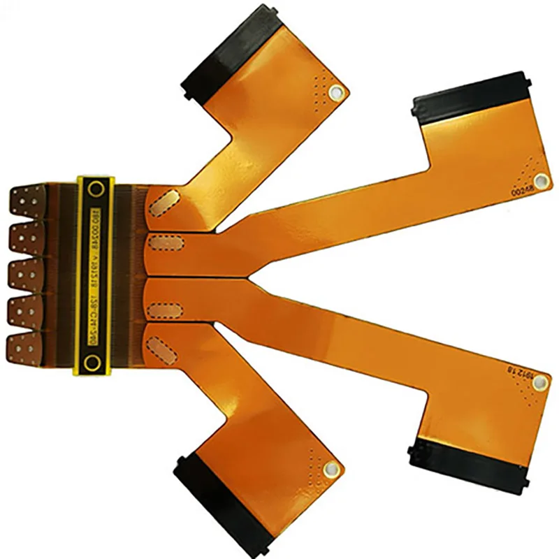
Multilayer Shaped Flexible PCB
- Review focus
- Layer stackup and shaped outline
- Input
- Gerber and fabrication drawing
- Purpose
- Manufacturability review
CUSTOM FLEX PCB FABRICATION & MANUFACTURING
Custom single-sided, double-sided, and multilayer flexible circuits with engineering support, material options, and quality-controlled fabrication for prototypes and production orders.
FLEXIBLE PCB PRODUCT
20+ YEARS. ONE FPC PARTNER.
Engineering Support · Prototype · Production
FREE DFM BEFORE YOU ORDER.
Stackup · Bend Areas · Stiffeners · Tolerances
NO MOQ. ORDER WHAT YOU NEED.
Prototype · Small Batch · Volume Production
QUALITY CHECKED. DELIVERED ON TIME.
Process Control · Electrical Test · Delivery Follow-Up
CUSTOM FLEXIBLE PCB PRODUCTS
Choose the bare-board construction that fits your routing, bend and installation requirements. Final capability is confirmed against the supplied fabrication files.
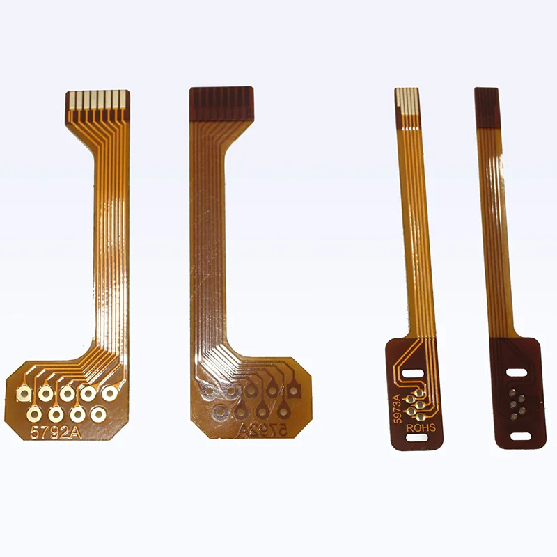
A compact bare FPC option for straightforward routing and space-constrained interconnects.
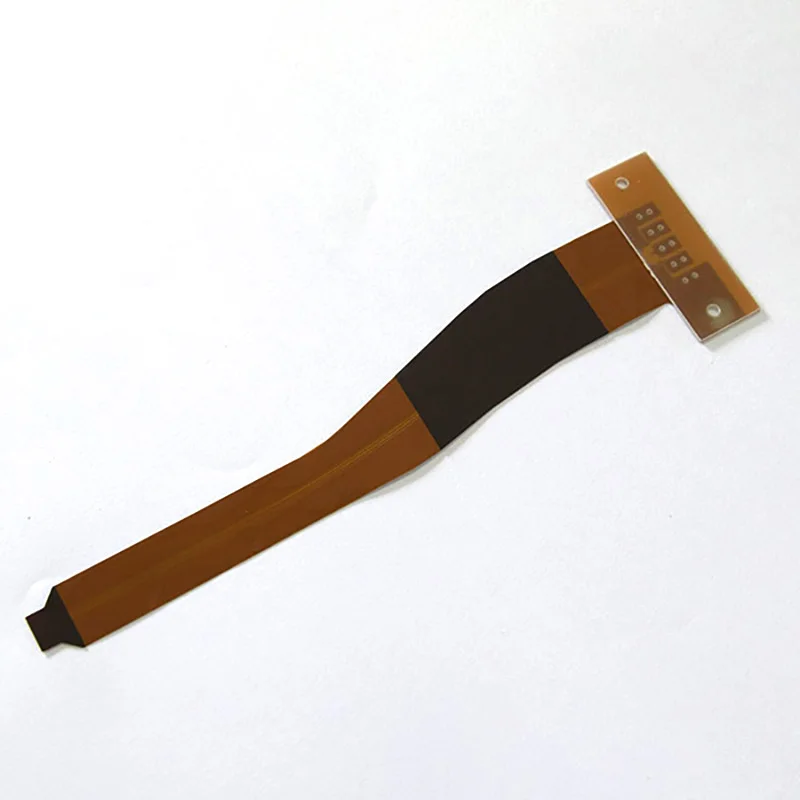
Custom outline, contact and stiffener details for board-to-board flexible connections.
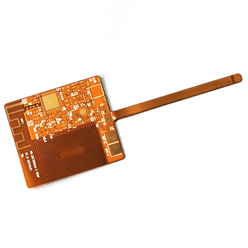
Multilayer routing with project-defined stackup and impedance requirements.
Custom branching outlines and reinforced connection areas for compact installations.
The values below are planning guidance from the supplied FPC capability source. Final values depend on construction, copper thickness, material availability and engineering review.
Need rigid-flex construction? View the separate rigid-flex product route →| Item | Typical FPC range | Review note |
|---|---|---|
| Layers | 1–4 layers | Higher layer counts require project review |
| Finished thickness | 0.06–0.60 mm | Construction-dependent |
| Fine line / space | From 3 / 3 mil at 18 μm finished copper | Special values require review |
| Base materials | Adhesive and adhesiveless PI | Material brand and thickness by project |
| Copper options | 0.33 oz, 0.5 oz, 1 oz; selected builds up to 2 oz | Availability and bend needs reviewed |
| Surface finish | ENIG, plated gold, OSP, immersion tin | Selected finish confirmed per drawing |
| Stiffeners | PI and pressure-sensitive tape options | Outline, thickness and adhesive reviewed |
| Controlled impedance | Project-defined | Stackup and tolerance confirmed before quote |
Share your files or critical specifications so our engineering team can review manufacturability before quotation.
Check My Design FeasibilityENGINEERING BEFORE RELEASE
Bend areas, copper construction, coverlay openings, and reinforcement details can affect bare-board fabrication and final installation. Share your design requirements so our engineering team can identify questions that should be resolved before manufacturing.
Define bend location, direction, radius and whether movement is static or repeated.
Align PI, copper type, finished thickness and layer arrangement with the application.
Review openings, reinforcement boundaries, connector support and adhesive needs.
Check critical features against copper thickness, registration and outline requirements.
FPC PROCESS & QUALITY EVIDENCE
Actual FPC fabrication equipment is shown below. Inspection and acceptance requirements are confirmed against the released construction and order documents.
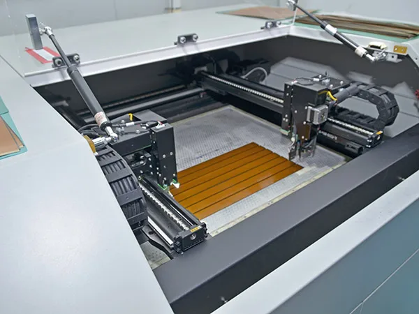
Process: Flying-probe testing is used for sample and small-batch FPC electrical checks.
Review: Test requirements are confirmed for the released fabrication data.
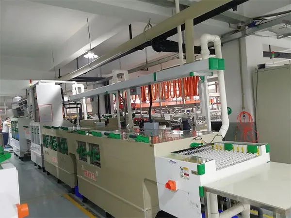
Process: Circuit patterns are formed through the developing, etching and stripping line.
Review: Copper construction and critical features are checked against the approved artwork.
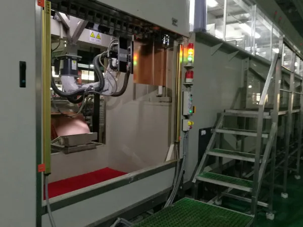
Process: VCP copper-plating equipment supports flexible PCB fabrication.
Review: The applicable copper construction is confirmed for each released build.
BARE FLEXIBLE PCB EVIDENCE
These are unpopulated flexible PCB manufacturing samples, not populated electronic modules or named customer success stories. Final construction is reviewed against each project’s files.
Review focus: trace routing, contact finish, outline and PI reinforcement.
Request a Similar Build Quote →Review focus: stackup, copper construction, impedance and fine features.
Request a Similar Build Quote →Review focus: routing density, branching outline, contact areas and stiffeners.
Request a Similar Build Quote →CHOOSE YOUR NEXT STEP
Share preliminary drawings or requirements to discuss fabrication feasibility and prototype pricing.
Request Prototype QuoteDiscuss approved specifications, production quantities, materials, and inspection requirements.
Request Production PricingStart with the requirements and concerns you can share. A complete file transfer is not required for the first discussion.
Evaluate an Alternative SupplierBUILT AROUND APPROVED REQUIREMENTS
Your flexible PCB supplier should help you confirm manufacturability, identify design concerns, and plan production around approved specifications—not simply accept a Gerber file.
Review layer count, materials, copper thickness, and critical tolerances against the actual construction.
Discuss bend areas, stackups, coverlay openings, and stiffeners before production release.
Align relevant inspection and acceptance criteria with your approved build requirements.
Coordinate early builds and repeat orders using approved fabrication data and revisions.

ENGINEERING CONTINUITY FOR LONG-TERM PROGRAMS
Bring flexible PCB design review, material selection, prototyping, bare-board fabrication and quality control together with an experienced manufacturing team.
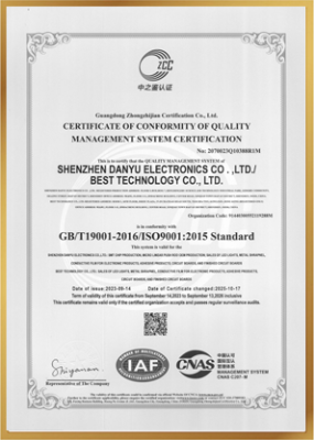
Match regulated and customer-controlled projects with the certificate and compliance documents applicable to the specific company, facility and order.
Learn More About Best FPC →QUALITY CERTIFICATIONS
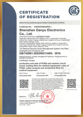
Give engineering and purchasing teams clearer evidence for material control, fabrication, inspection and final release within the approved manufacturing scope.
Request the current certificate, facility and scope documents required for your supplier review.
FLEXIBLE PCB INSIGHTS
Explore practical BestFPC articles on flex materials, reliability, compact routing and prototype planning.
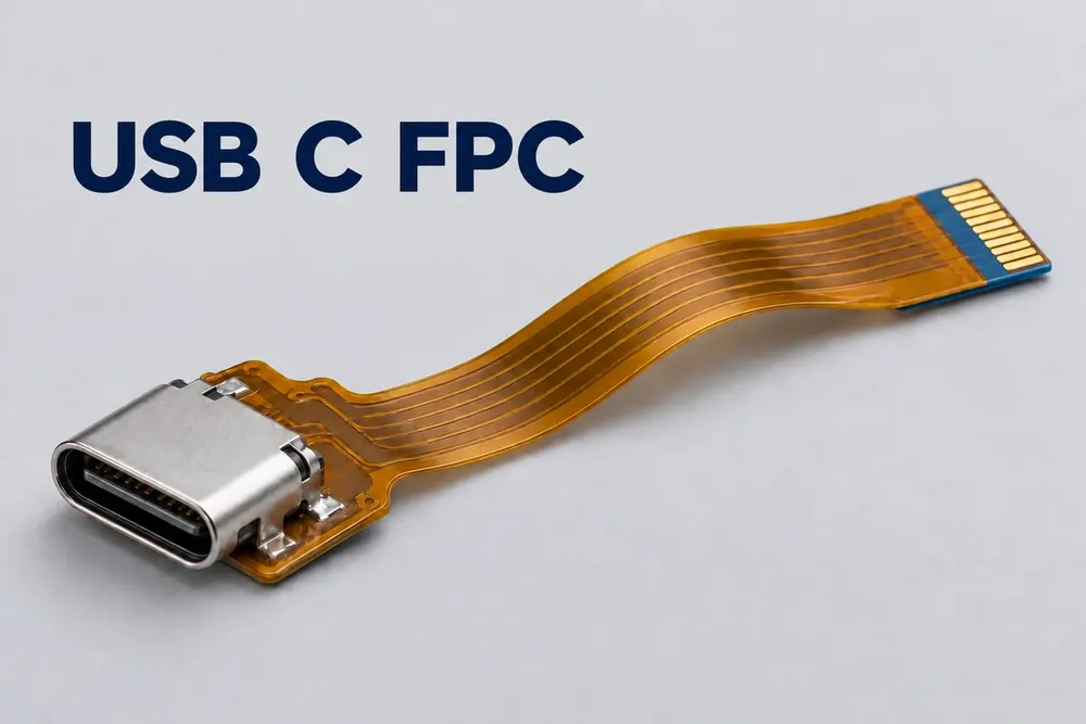
Review connector orientation, installed routing and electrical requirements before choosing a custom USB-C flex circuit.
Read More →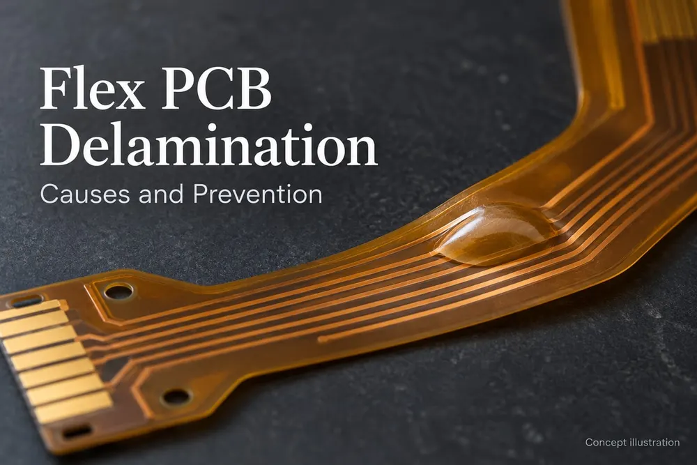
Understand how moisture, heat, bonding quality and mechanical loads can contribute to layer separation.
Read More →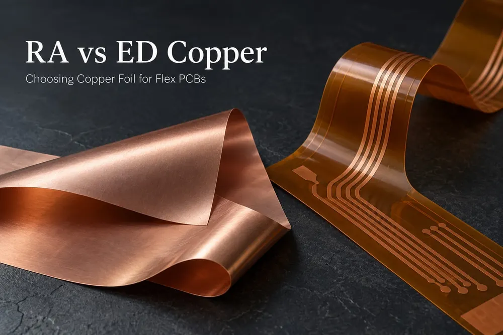
Compare copper choices against the installation, bend behavior, foil thickness and complete FPC stackup.
Read More →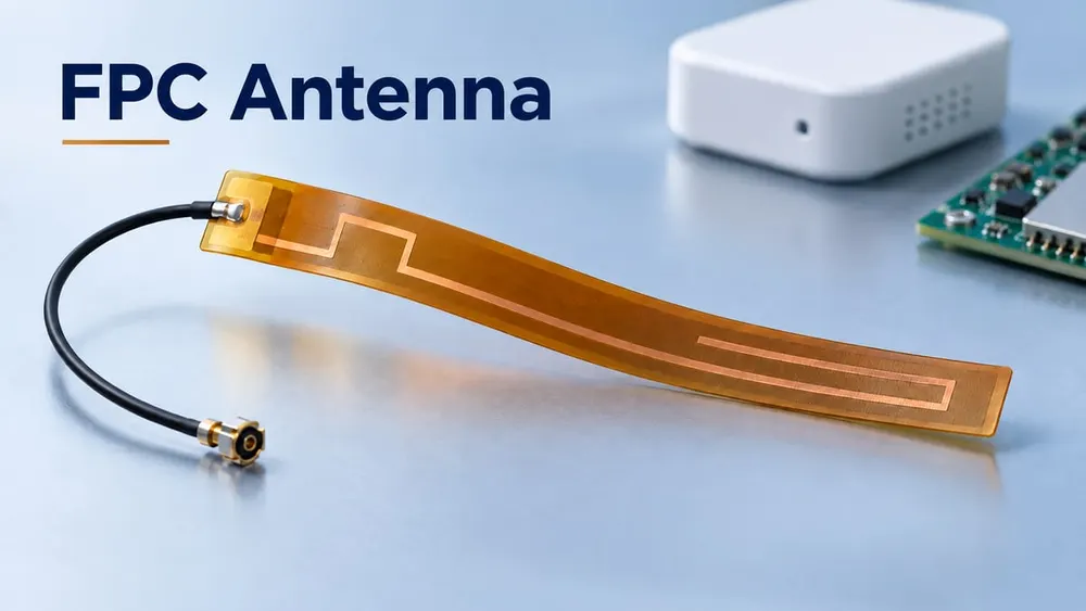
Plan band coverage, antenna placement, cable routing and available device space as one installed system.
Read More →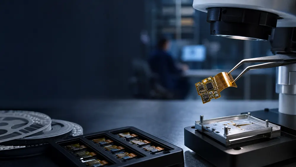
See how material selection, stackup control and manufacturability shape miniaturized multilayer FPC designs.
Read More →
Compare design inputs, manufacturing constraints and planning considerations for faster flex PCB prototypes.
Read More →START WITH THE ACTUAL PROJECT
Share your Gerber files, drawings, estimated quantities, and critical requirements. Our team can review your bare flexible PCB project and prepare a quotation based on your actual design.
Prefer email? sales@bestfpc.com →
BUYER QUESTIONS
Practical questions engineers and sourcing teams raise before releasing a bare flexible circuit for quotation.
Send your Gerber files if available, plus the outline or fabrication drawing, layer count, target thickness, copper, surface finish, bend and stiffener requirements, and quantity. If the package is incomplete—or you are transferring an existing supplier stackup—send what you have. We will identify the missing inputs and the shortest path to a reliable quotation.
No MOQ. Start with one prototype, order a small batch or request volume pricing when you are ready. Validate the design first and scale when the project is proven instead of committing to more boards than you need.
Layer count, finished size, panel utilization, material and copper construction, fine features, impedance, surface finish, stiffeners, tooling and quantity can all affect price. Share the requirements that are truly critical, and our free DFM review can help identify avoidable cost before you order.
Timing depends on the construction, material availability, quantity, tooling and special processes. We confirm a project-based schedule after reviewing the build, then track the approved order through production and delivery follow-up so you receive a realistic plan—not an unsupported generic promise.
Tell us whether the circuit is bent once for installation or moves repeatedly, then provide the bend location, direction, installed radius, expected cycles and operating environment. We will review the construction around the actual motion so fatigue risks can be addressed before production.
The right construction depends on bend behavior, layer count, routing density, impedance, finished thickness and operating conditions. We can review adhesive or adhesiveless PI, copper type and weight, and the proposed layer arrangement so the quotation is based on a build that fits the application.
Stiffeners are commonly used at connector, contact and component-support areas. Mark the side, outline, thickness and installed-height limit on the drawing. PI and pressure-sensitive-tape options can be reviewed directly; FR4 and other requested materials are confirmed for the specific build.
Tell us whether the exposed area is a solder pad, connector tail or repeated-wear contact. We will review ENIG, plated gold, OSP or immersion tin against the actual use so you can avoid both an under-specified contact and unnecessary finishing cost.
Requirements are confirmed against the released fabrication data. The documented FPC process includes circuit-formation and copper-process controls plus flying-probe open/short testing for sample and small-batch builds. Add any required report or acceptance criteria to the RFQ so it can be included in the reviewed manufacturing scope.
Yes. BESTFPC provides a free pre-order DFM review covering the proposed stackup, bend areas, coverlay openings, stiffeners, critical features and tolerances. Catching open issues before release can prevent avoidable revisions, delays and costly remakes.