


 2026-10-13
 BEST
BESTChoosing between RA vs ED copper starts with how your flex PCB will move. A circuit that bends during installation has different demands from one that moves repeatedly throughout the product’s life. The copper foil grade, finished copper thickness, and layer construction all influence that decision.
RA copper is a common starting point for repeated-flex applications, while suitable ED grades can serve both fixed installations and demanding flex designs. BestFPC can help review the manufacturing implications of your proposed material and stackup. To discuss your project, contact sales@bestfpc.com.
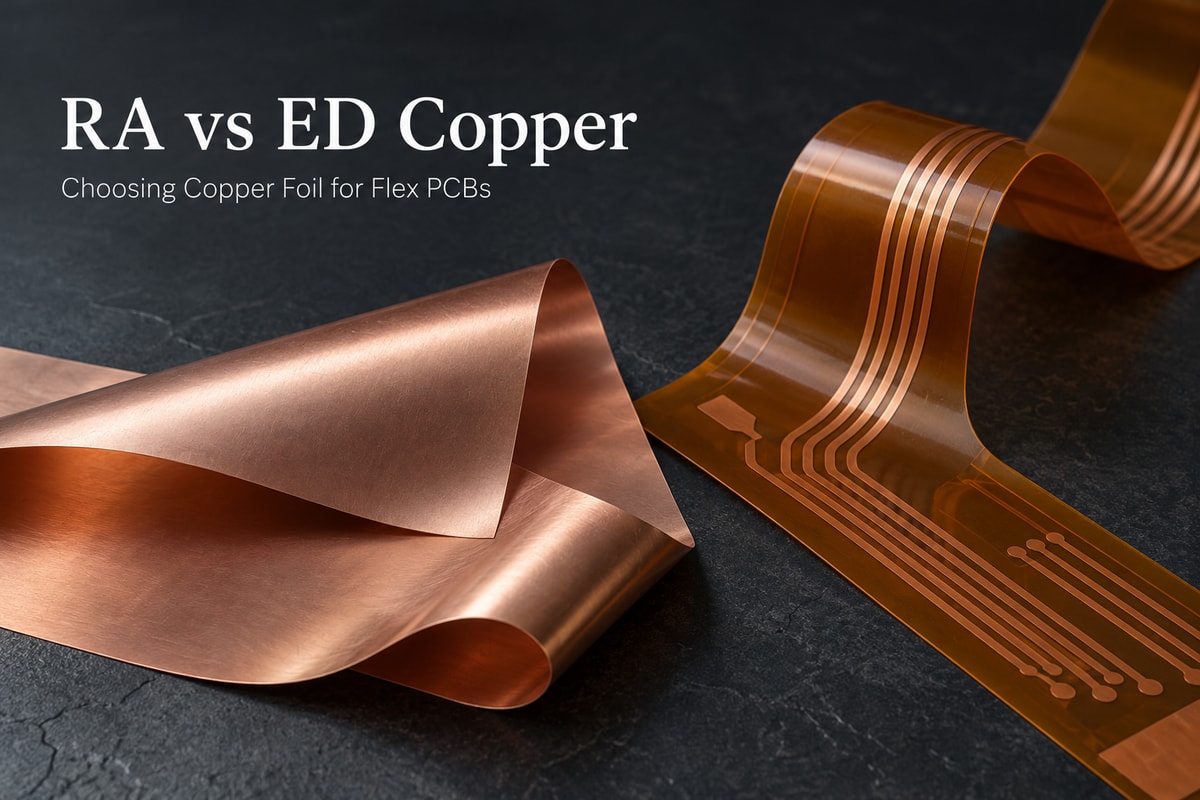
RA vs ED Copper: What Is the Difference?
RA stands for rolled annealed copper, while ED stands for electrodeposited copper. The names describe different manufacturing routes. These routes influence the foil’s grain structure, but the specific grade and processing condition determine its properties.
The two copper foils are produced differently:
- Rolled annealed copper foil: Copper is mechanically rolled to reduce its thickness and annealed to change its metallurgical condition. The resulting properties depend on the rolling and heat-treatment process.
- Electrodeposited copper foil: Copper is deposited from an electrolyte onto a rotating drum and removed as foil. Deposition conditions and subsequent treatment help control its structure and surface characteristics.
| Comparison | RA copper | ED copper |
|---|---|---|
| Repeated bending | Commonly considered for dynamic flex circuits | Specialized grades are available for repeated bending |
| Material selection | Compare the specific rolled foil grade and condition | Compare the specific deposited foil grade and treatment |
| Surface characteristics | Depend on the foil and its surface treatment | Include conventional and low-profile options |
| Practical choice | Evaluate against the required motion and stackup | Evaluate against the same motion and stackup requirements |
For an ED copper vs RA copper comparison, the useful question is which available material meets the circuit’s electrical and mechanical needs. The label alone cannot establish finished-board reliability.
Which Copper Foil Is Better for Dynamic Flex PCBs?
RA copper is often a strong candidate for dynamic flex PCBs because suitable grades are developed for repeated deformation. However, ED copper should be evaluated by grade rather than automatically excluded.
For example, JX Advanced Metals describes rolled copper grades whose recrystallized grain structure supports flexible applications. Mitsui Kinzoku also offers electrodeposited copper foil developed for repeated bending. These are reasons to compare actual material options rather than apply a blanket rule.
Start with the circuit’s motion:
- Bending during installation: A circuit formed into position and then held still may use a suitable RA or ED construction. The installation bend still needs to avoid excessive strain.
- Repeated movement in service: Compare fatigue performance for the proposed foil and stackup under representative bend radius, travel, and cycle conditions.
- Combined bending and twisting: Evaluate the actual motion path. Results from a simple bending test may not represent torsion or movement concentrated at an attachment point.
A supplier’s foil test is useful for comparing materials under that test’s conditions. Prototype testing of the finished circuit is needed to assess the intended application.
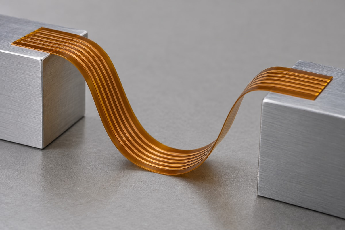
How Do Copper Thickness and Stackup Affect Flex Life?
Copper thickness and layer construction affect the strain imposed on a conductor during bending. A well-chosen foil can still fail early if the finished circuit concentrates too much strain in the flexing area.
For a given bend radius, conductors farther from the stackup’s neutral axis—the region with little longitudinal stretching or compression—experience more strain. Increasing thickness or changing the layer arrangement can therefore change the mechanical demands on the copper.
Three construction details deserve particular attention:
- Finished copper thickness: Review the base foil plus any added plating in the bend area. The starting foil thickness may differ from the conductor thickness in the finished board.
- Complete flexible stackup: Polyimide, adhesive, coverlay, and copper layers collectively determine the structure that bends. Comparing foil samples alone leaves out these effects.
- Local stiffness changes: Stiffener edges, component areas, and rigid-to-flex transitions can concentrate movement. Their placement affects where the circuit actually bends.
Flexible PCB copper thickness also affects resistance and current-carrying requirements. The aim is to balance electrical needs with mechanical flexibility, then validate the selected construction under the intended motion.
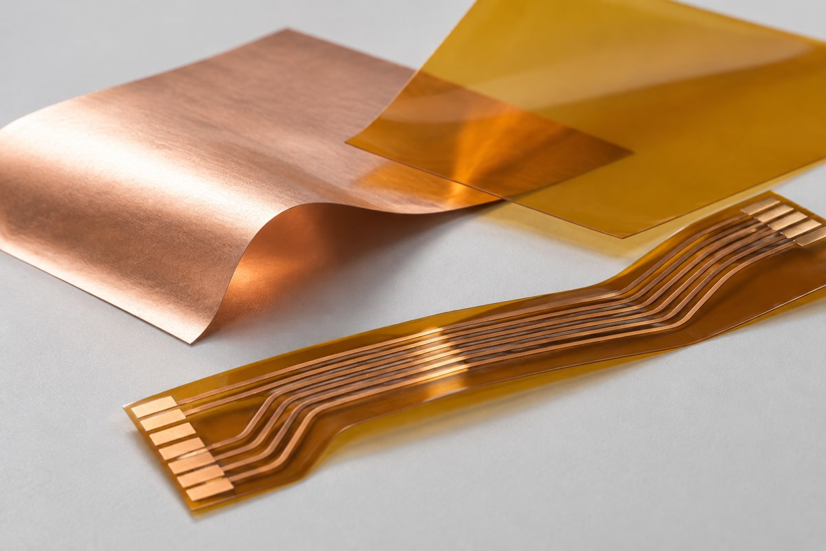
Can Both RA and ED Copper Be Used in Adhesiveless Flex PCBs?
Yes. Copper foil type and the presence of an adhesive layer are separate material choices. RA copper does not inherently require an adhesive between the copper and polyimide.
DuPont’s Pyralux AP data sheet, for example, describes an adhesiveless all-polyimide laminate available with RA, ED, and double-treated RA copper options. Availability depends on the particular laminate construction.
Keep these two specifications separate:
- Copper foil specification: The foil grade, thickness, treatment, and required mechanical or electrical properties.
- Laminate specification: The dielectric material, thickness, and adhesive or adhesiveless construction.
An adhesiveless base laminate can still be used with an adhesive-backed coverlay elsewhere in the finished circuit. Review the complete stackup when assessing thickness and flexibility.
Is RA or ED Copper Better for High-Frequency Flex PCBs?
Neither label guarantees lower signal loss. For high-frequency flex PCBs, copper surface characteristics must be considered alongside the dielectric, conductor geometry, and operating frequency.
Copper roughness can contribute to conductor loss as high-frequency current becomes concentrated near the conductor surface. Compare the relevant treated surface using consistent roughness measurements.
Low-profile ED copper demonstrates why the manufacturing label is insufficient. Rogers offers a reverse-treated ED foil with a surface treatment intended to reduce conductor loss. This is evidence about foil characteristics, not a recommendation to use its rigid laminate system in a dynamic flex circuit.
For a high-frequency flex design, compare:
- Foil surface data: Identify the relevant surface and measurement method; roughness values obtained using different metrics are not directly interchangeable.
- The complete transmission line: Include dielectric properties, trace dimensions, and the surrounding copper structure.
- Mechanical requirements: A low-loss material option must also suit the intended bending conditions.
Use material data and, where needed, measurements on a representative circuit to assess the combined electrical and mechanical result.
RA vs ED Copper Cost: What Affects the Price?
RA vs ED copper cost depends on the specified material and manufacturing route. A fixed percentage premium is not a reliable basis for every flex PCB project.
The main price factors include:
- Copper grade and treatment: Specialized flex performance or a particular surface profile can change material cost.
- Laminate construction: Copper thickness, dielectric thickness, and adhesive structure affect the available material options.
- Availability and order quantity: Stocked materials, minimum purchasing quantities, and production volume can change the quotation.
- Fabrication requirements: Layer count, plating, feature sizes, and processing requirements influence the finished-board price.
A meaningful RA vs ED copper price comparison uses equivalent board requirements and clearly identifies the material difference.
For a circuit that remains fixed after assembly, a material proven suitable for that construction may provide the best value. For repeated movement, the comparison should also account for validation effort and the consequences of premature failure. The lower-priced foil is useful only when the finished circuit meets the application’s needs.
Why Choose BestFPC for Your Flex PCB Project?
BestFPC brings FPC manufacturing and assembly support together to help engineers turn an approved circuit design into practical prototypes and production builds. For an RA or ED copper decision, that means reviewing the proposed material alongside the construction that will actually be manufactured.
- DFM review before fabrication: Experienced FPC engineers review the proposed construction and provide process compatibility advice, helping identify manufacturing concerns before samples are built.
- Prototype and small-batch support: Sample production gives engineering teams boards for assembly, fit checks, and application-specific validation before a larger order.
- Integrated FPC and PCBA services: FPC fabrication, component sourcing, assembly, and agreed testing can be coordinated through one supplier.
- Engineering support through production: Reviewing fabrication and assembly requirements together helps keep material, stackup, and process decisions consistent as the project progresses.
This coordinated approach helps you evaluate a manufacturable flex PCB construction and carry the approved requirements into production.
FAQs About RA vs ED Copper
Is RA copper always better than ED copper?
No. RA is often considered for repeated-flex applications, but the better choice depends on the foil grade, finished construction, and use conditions. A suitable ED material may meet the requirements without a change to RA.
Can ED copper be replaced with RA copper without changing the design?
Treat it as a material change requiring review. Even when the nominal copper thickness is unchanged, laminate availability, surface treatment, processing, and mechanical performance may differ. Determine which fabrication and application tests need to be repeated.
Does RA copper guarantee a specific number of bend cycles?
No. Bend life depends on the entire circuit and its operating conditions. A cycle count is meaningful only with a defined stackup, bend radius, motion, test method, and failure criterion.
Is a copper foil bend test enough to approve a dynamic flex PCB?
A foil test helps characterize the material. Approval of a dynamic flex PCB should also consider representative finished-circuit testing, including the intended mounting arrangement and movement.
Should the PCB drawing specify only “RA copper” or “ED copper”?
Use the material definition needed to preserve the design’s requirements. This may include the laminate or foil grade, thickness, surface treatment, and agreed substitution limits. Coordinate that definition with the fabricator so acceptable alternatives can be evaluated consistently.
Planning a flex PCB with RA or ED copper? Send your Gerber files, proposed stackup, quantity, and intended bending conditions to sales@bestfpc.com. Include a BOM if assembly is required. BestFPC can review manufacturing feasibility and discuss suitable production options for your project.


.png)
.png)
.png)
.png)

.png)