


 2026-10-13
 BEST
BESTAn FPC antenna gives a compact wireless device more options for antenna placement, especially when the main board is crowded. To choose one, start with three questions: does it cover the required radio bands, can it fit in a suitable location, and does it perform well inside the assembled enclosure?
BestFPC supports FPC prototyping, fabrication, and assembly for customer-approved circuit designs. If you are developing a custom antenna circuit, send your files and construction requirements to sales@bestfpc.com to discuss manufacturability and sample production.
What Is an FPC Antenna?
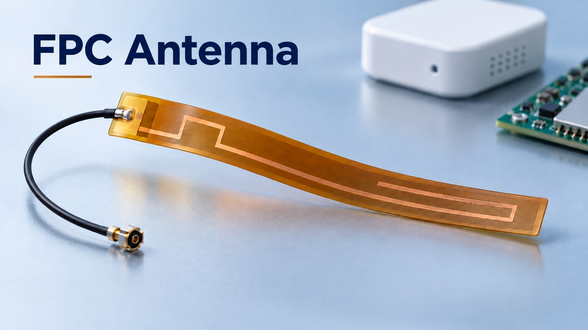
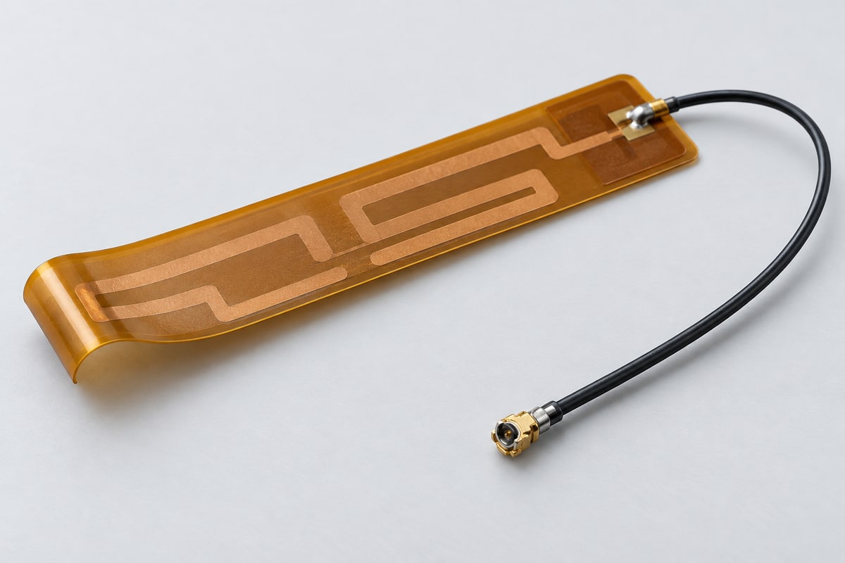
An FPC antenna is an antenna formed on a flexible printed circuit. A conductive pattern on an insulating film provides the antenna structure. Many embedded versions use a polyimide substrate, adhesive backing, and a coaxial cable connected to the radio board.
The practical advantage of this flexible antenna is placement freedom: the radiating element can occupy a suitable area of the housing away from the main board. This can help when the board edge has little room for an antenna and its required clearance.
FPC describes the construction. The particular antenna design determines its frequency bands, feed connection, and mounting requirements.
FPC Antenna vs. PCB Antenna: Which Fits Your Device?
Choose an FPC antenna when a separate mounting location helps you use the available space. A main-board trace antenna is worth considering when the PCB can accommodate the required antenna area and keepout.
Because an FPC is also a printed circuit, the comparison below uses PCB antenna to mean a main-board trace antenna or a separate rigid antenna board.
| Antenna construction | When it is worth considering | Main integration tradeoff |
|---|---|---|
| Separate FPC antenna | A suitable housing surface is available away from the main board | Adds mounting and a feed connection; performance depends on the chosen location |
| Main-board trace antenna | The board layout can reserve the antenna area and clearance | Saves a separate antenna mounting operation but commits space on the host PCB |
| Separate rigid PCB antenna | A dedicated antenna board fits the product's mechanical layout | Needs room and support for a fixed board shape and its connection |
Flex antennas may suit a product with an accessible plastic wall above the electronics. A trace antenna may suit a layout with a clear board edge. Compare both in the intended enclosure: construction alone does not determine wireless range.
When Should You Choose a 2.4 GHz FPC Antenna?
A 2.4 GHz FPC antenna can suit Bluetooth and 2.4 GHz Wi-Fi devices when its operating band and installation requirements match the product. Make the choice around the radio configuration:
- Bluetooth or 2.4 GHz Wi-Fi: Check performance across the channels the device uses, along with the specified feed interface and mounting conditions.
- Wi-Fi using additional bands: If the device also uses 5 GHz or 6 GHz, select an antenna arrangement specified for those bands. A 2.4 GHz rating alone does not establish that coverage.
- Several radios in one enclosure: Evaluate antenna locations together so the layout accommodates their spacing and possible interactions.
For a board-integrated alternative, the 2.4GHz PCB antenna pattern and keepout also need to be preserved during manufacturing. Choose the frequency coverage and installation approach before committing to the antenna outline.
How Do Materials and Geometry Affect FPC Antenna Design?
FPC antenna design depends on both the conductive pattern and the materials around it. A part can fit mechanically yet behave differently if its electrical construction changes.
Four details deserve particular attention:
- Conductor geometry: The pattern and feed dimensions help establish the antenna's response. Preserve the approved artwork, and have the RF designer assess changes to critical features.
- Substrate and thickness: The dielectric material surrounding the conductor is part of the design. Specify the material and layer thicknesses so a substitution is reviewed before production.
- Coverlay and adhesive: These layers add material around the antenna. Define their construction and openings so the manufactured part represents the version evaluated during development.
- Installed bend: Evaluate the shape the antenna will take in the product. A flat sample and a curved installation should not be assumed to perform identically.
Single-layer flex antennas use one conductor layer for the circuit pattern, but layer count alone does not establish suitability. The pattern, material construction, and installed condition must work together. DFM review can identify fabrication constraints; changes affecting the RF design need the design owner's assessment.
Where Should a Flex Antenna Be Placed Inside the Enclosure?
Place a flex antenna where its mounting and clearance requirements can be maintained after the product is assembled. Select the location while the enclosure and board layout can still be adjusted.
Evaluate each candidate position in three steps:
- Check the surroundings: Identify nearby PCB ground areas, batteries, displays, and metal parts. Apply the selected antenna's clearance guidance to the actual arrangement.
- Check the mounting surface: Confirm that the housing material, coating, and curvature suit the antenna's installation requirements. An available adhesive area is only useful if the antenna can operate there.
- Compare installed performance: Test candidate locations with the enclosure closed and the internal parts in position. Use the same setup so the comparison reflects the placement change.
Record the selected location and orientation in the assembly drawing. Use the model's specified clearances; there is no single separation distance that applies to every FPC antenna.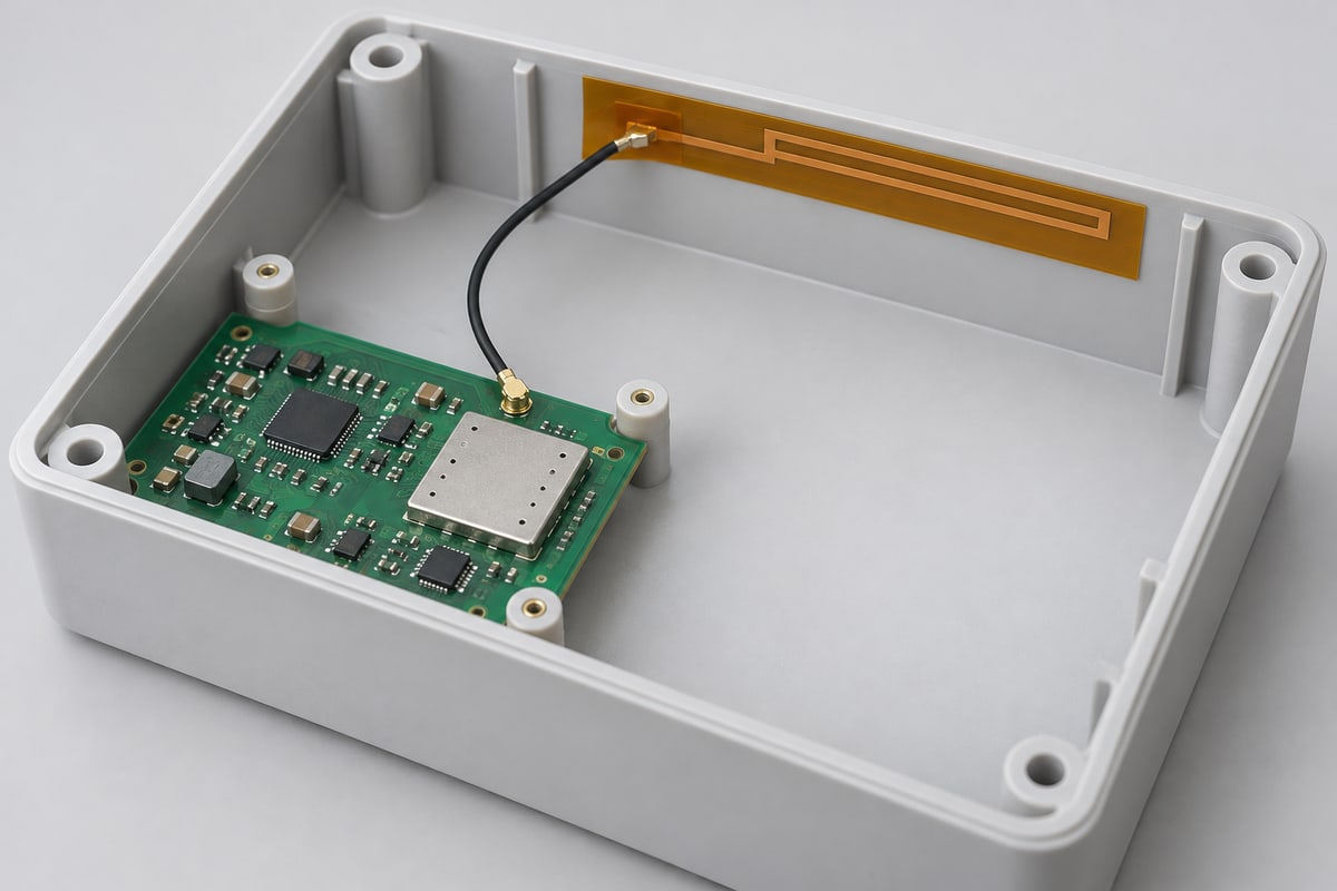
How Do Coaxial Cables and Connectors Affect Antenna Performance?
Cable length, routing, and connector fit affect signal loss, interference, and connection reliability. Focus on these three factors when connecting the antenna to the radio board:
- Cable length: For the same cable type and frequency, a longer run adds loss. Choose a length that reaches the mounting location without excess cable, while leaving enough slack to avoid tension.
- Cable routing: Keep the route away from noisy circuitry and follow the cable's bend limits. Avoid pinching it when the enclosure closes, and support it so movement does not pull on the connector.
- Connector fit: U.FL and MHF4 are different systems. Match the cable connector to the specified board receptacle; a similar appearance does not establish compatibility.
Once this arrangement has been tested, keep the cable type, length, route, and mating parts consistent in production. Review substitutions before using them in the build.
How Should Antenna Performance Be Verified in the Finished Device?
Test the antenna with the enclosure closed and the battery, display, and cables in their intended positions. Then answer three questions about the assembled product:
- Does it remain matched across the required band? Measure return loss or VSWR in the installed configuration. If the response changes after assembly, investigate the mounting position and nearby parts before releasing the design.
- Does it radiate effectively in the directions that matter? Check efficiency and radiation patterns. A good match can coexist with poor radiation performance, so a favorable VSWR reading alone cannot establish usable wireless coverage.
- Does the device maintain the required connection in use? Evaluate communication at the intended distances and orientations, including representative hand or body proximity for products used that way. Record relevant pass/fail measures, such as packet loss or connection stability.
Dimensional and electrical inspections remain part of manufacturing control. RF validation establishes whether the completed device performs as intended, using acceptance limits defined by the product requirements. Agree on the test scope with the responsible RF engineering team or test provider.
Why Choose BestFPC for Your FPC Antenna Project?
BestFPC helps engineering teams turn an approved flexible circuit design into parts for evaluation and production. For an antenna project, this means coordinating fabrication and assembly around the construction your team has specified.
- DFM review before fabrication: Identify manufacturing constraints in the proposed FPC construction before samples are built, giving your engineers time to assess necessary changes.
- Prototype and small-batch support: Obtain evaluation quantities to check the circuit in its intended assembly before committing to a larger production run.
- FPC manufacturing and assembly coordination: Combine fabrication, component procurement, and applicable assembly work under an agreed scope, reducing separate supplier handoffs.
- Engineering support through revisions: Keep material choices, drawing revisions, and assembly requirements aligned as the project moves from samples to production.
This support helps your team address manufacturing issues early and carry the approved construction into subsequent builds. Antenna performance remains tied to the RF design and its validation in the finished device.
FAQs About FPC Antennas
Can an FPC antenna be bent to fit a curved housing?
Yes, when the selected design permits that bend. Follow its bend limits and evaluate the installed shape. Sharp folding or repeated flexing requires specific qualification.
Does an FPC antenna need a ground plane?
It depends on the design. Some commercial FPC antennas are ground-plane independent. Check the particular model's requirements and its clearance from nearby metal and the host board.
Can the antenna be cut shorter to fit the enclosure?
Trimming the conductive pattern changes the antenna design. Have the antenna designer assess and validate the revised part before using it.
Can the same FPC antenna be used in several products?
Possibly, if its bands and installation requirements suit each product. Evaluate it in each enclosure because mounting positions and internal arrangements can differ.
Why can performance change after the enclosure is assembled?
The housing and nearby parts become part of the antenna's operating environment. If performance changes, compare the installed position, cable route, and surrounding parts with the evaluated configuration.
Ready to move your FPC antenna circuit into prototype production? Send your Gerber files, construction drawing, quantity, and relevant assembly details to sales@bestfpc.com. BestFPC can review the proposed build and discuss fabrication and assembly support for your next development stage.


.png)
.png)
.png)
.png)

.png)