


 2026-10-13
 BEST
BESTAn endoscope PCB must fit into an assembly that also needs room for optics, electrical connections and, depending on the instrument, working channels and articulation mechanisms. Choosing the board by outline alone can leave too little space for the assembled components or force the interconnect into an unsuitable bend.
For medical device developers, the useful starting point is the board’s location and movement. A compact camera connection, a flexible section inside the handle and a processor board have different priorities. Matching each circuit to its actual role helps control assembly complexity without sacrificing the electrical path that carries the image. If you are preparing an endoscope PCB prototype, contact BestFPC at sales@bestfpc.com to discuss whether your proposed flex or rigid-flex construction is practical to manufacture.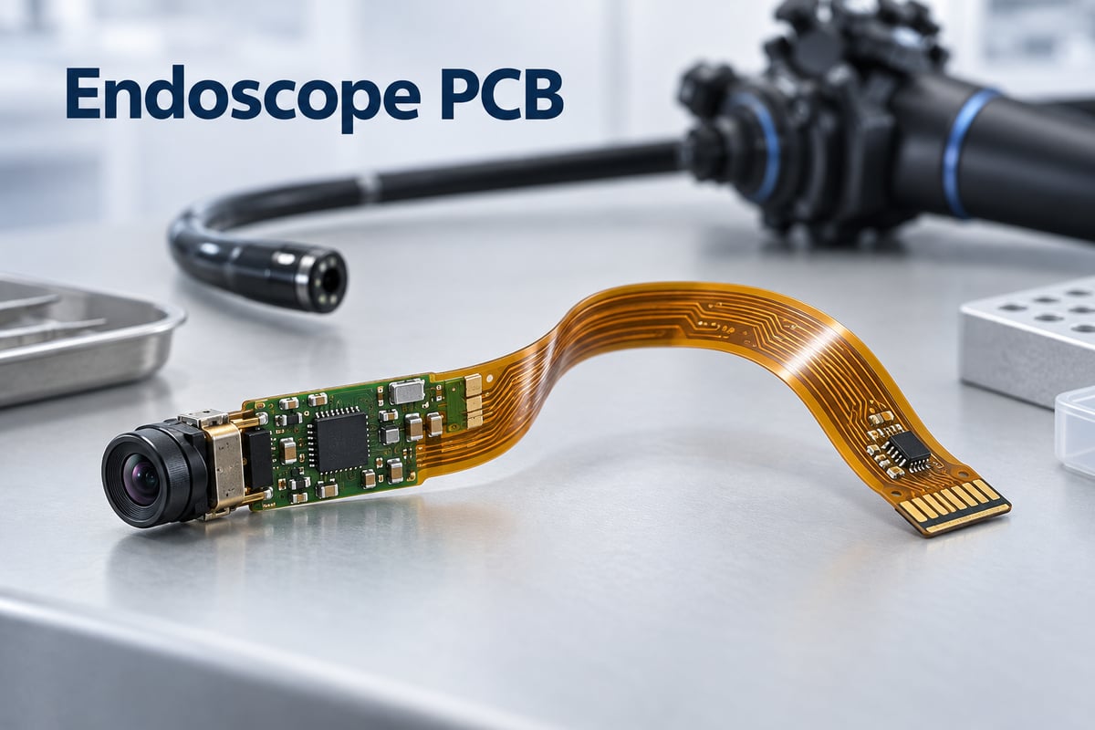
Where Does the PCB Fit Inside a Medical Endoscope?
An endoscope can contain several circuit assemblies, and their locations determine whether compact dimensions, flexibility or component support matters most.
| Location | Possible electronic role | Main PCB consideration |
|---|---|---|
| Distal tip | Camera-module connection and, in some architectures, local illumination | Assembled size, connection access and heat generation |
| Insertion section | Connection between the distal electronics and the proximal system | Available cross-section, movement and interconnect construction |
| Control handle | Buttons, connectors and interface electronics | Three-dimensional fit and support around mounted components |
| External processor or control unit | Image processing, power and system interfaces | Routing, power integrity and component density |
These are possible functions, not a requirement to place a PCB in every section. For example, OMNIVISION’s OVMed cable modules connect miniature camera modules through thin micro-coaxial cables. A long flex circuit is therefore one possible interconnect approach, rather than a universal feature of an endoscope.
At the distal tip, compare the complete assembled envelope with the space available beside the optics. Sensor-package height, solder connections and any local LEDs can matter as much as the bare-board dimensions. Where illumination is located elsewhere, the tip has a different electrical and thermal arrangement.
When Does an Endoscope Need Flex or Rigid-Flex PCB?
Choose flex when the circuit must follow the enclosure or provide a compliant connection. Consider rigid-flex when populated rigid sections need an integrated flexible connection between them.
Medical flex circuits with local stiffeners can support connectors or component areas while allowing other sections to conform to the endoscope handle. A stiffener supplies mechanical support; it does not turn that area into a multilayer rigid PCB. Rigid-flex becomes useful when the rigid sections themselves need more routing or component-mounting space.
The distinction between installation and operation is equally important. A circuit folded into a fixed position during assembly has a different duty from a circuit that moves whenever the scope articulates. A construction that fits successfully once has not demonstrated suitability for repeated movement.
Use the simplest construction that satisfies both the electrical layout and the mechanical motion. Adding layers to solve routing congestion also changes the bending behavior, so a denser rigid area may be preferable to increasing layers throughout the flexible section.
How Can the Flex Circuit Handle Endoscope Bending?
The flexible section needs a construction matched to its actual bend path, including where motion begins and where the circuit is constrained. Flexibility of the base film alone does not establish circuit life.
For a moving section, the design review should address four connected choices:
- Copper and stackup: Rolled annealed copper is commonly preferred for repeated flexing. Copper thickness and the complete dielectric, adhesive and coverlay construction affect mechanical behavior.
- Bend geometry: A controlled curve distributes movement more predictably than a sharp crease. The permitted radius must reflect the finished construction and required service life.
- Feature placement: Keep component joints and vias out of the active bending zone where practical. Place them in supported areas so movement is carried by the intended flexible span.
- Transition support: Avoid forcing the circuit to hinge directly at a stiffener edge or rigid-to-flex junction. The installed routing must accommodate the transition into the moving area.
A broad loop that looks acceptable outside the housing can become a tight bend once the handle closes. Mechanical trials should therefore reproduce the installed position, not just test a loose circuit on the bench. Evaluate copper, thickness, layer count and shielding together; no single bend-radius multiplier proves life for every endoscope construction.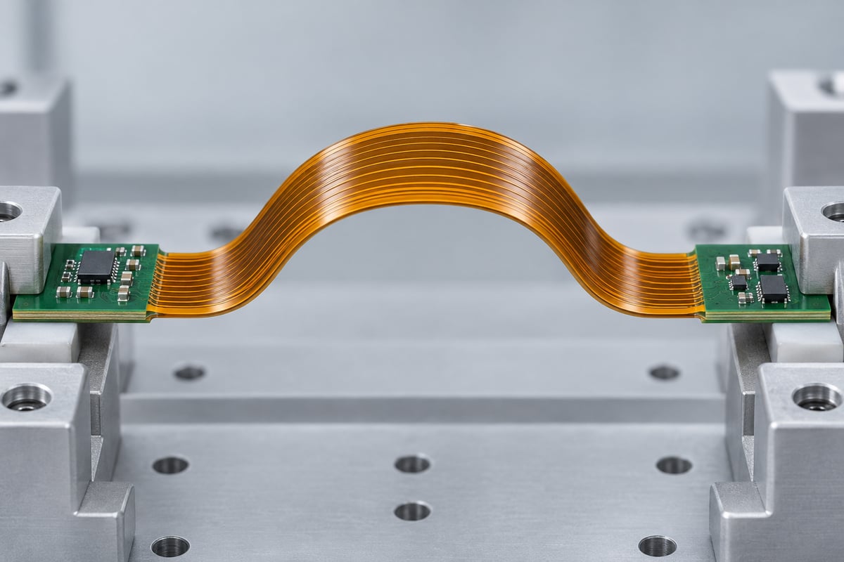
How Does the PCB Connection Affect Endoscope Image Quality?
The PCB connection must carry the selected camera interface while maintaining stable power and appropriate signal return paths. Image resolution alone does not specify the required interconnect.
Start with the actual sensor or camera module’s interface requirements. Analog outputs, differential links and other digital interfaces place different demands on routing and termination. Do not assign a generic impedance target simply because the assembly is called an endoscope PCB.
Where controlled impedance is required, trace geometry and the manufactured stackup must work together. Include the connector, flex section and any cable transitions when evaluating the complete connection. A well-controlled trace cannot compensate for an unsuitable transition elsewhere in the path.
Power integrity also matters. Camera load changes can disturb supply rails, while switching circuits can couple noise into sensitive nodes. Supply ripple, current-loop geometry and power/ground continuity can affect camera performance. Evaluate these together with the selected camera module and its interface requirements.
During development, compare image behavior across the intended operating modes. If a disturbance appears only during illumination changes or articulation, that timing provides a useful starting point for investigating power coupling or an intermittent connection. It does not, by itself, identify the fault.
What Changes Between Single-Use and Reusable Endoscope PCBs?
The difference is the operating and processing lifecycle the assembly must survive. That lifecycle changes material and construction decisions as well as the validation program.
A single-use instrument can still undergo substantial articulation during one procedure. Its electronics must also tolerate assembly, storage and the specified sterilization process where applicable. Single-use does not mean a flex circuit can be designed without considering fatigue or environmental exposure.
For a reusable instrument, repeated processing may introduce additional chemical, moisture and thermal exposure. The relevant conditions depend on the device’s validated process and how well the electronics are isolated from it. Coverlay, adhesives, solder joints and protective materials must be considered as part of the assembled construction.
Do not assume every reusable endoscope is steam sterilized. Reprocessing compatibility must be established for the actual instrument and its accessories. A substrate’s temperature rating cannot establish the compatibility of the complete endoscope assembly.
What Drives Endoscope PCB Manufacturing Cost?
Cost depends on how difficult the circuit is to fabricate, handle, assemble and verify—not just how little material the finished board occupies.
A miniature outline may require tighter registration, finer features or more demanding assembly handling. Likewise, an integrated rigid-flex construction can increase board fabrication cost while removing separate interconnect assembly steps. Compare these options at the assembled-product level.
| Cost driver | Why it matters | Practical way to control it |
|---|---|---|
| Fine features and small holes | Increase fabrication demands | Use them where the approved routing requires them |
| Layer count and rigid-flex construction | Add processing and stackup complexity | Keep complexity concentrated in the sections that need it |
| Irregular outlines and long flex tails | Affect panel utilization and handling | Review panel layout before fixing the production format |
| Component placement and access | Influence tooling and assembly difficulty | Consider the assembled shape as well as the flat artwork |
| Inspection and functional coverage | Require time, access and sometimes fixtures | Define tests around the defects they need to detect |
A useful cost comparison holds the construction and acceptance requirements constant. Comparing an unassembled flex quotation with a populated rigid-flex quotation will not show which route is more economical for the finished product.
How Are Endoscope PCBs Tested for Reliable Imaging and Bending?
Different tests address different failure modes. Electrical continuity, assembly inspection, image operation and bend endurance should have separate acceptance criteria.
Bare-board electrical testing checks the circuit’s connections and isolation. Dimensional and visual inspection help establish whether the supplied circuit matches its drawing. After assembly, inspection addresses component placement and solder-joint quality.
Functional imaging requires a suitable powered setup with the relevant camera, interface and receiving electronics. A board that passes a continuity test has not yet demonstrated correct image operation. The functional test should exercise the operating modes defined for the project, rather than rely only on a single successful startup.
Bend validation must also reproduce meaningful mechanical conditions. Radius, travel, constraint points and cycle count need to represent the intended duty. Where intermittent faults are a concern, monitoring the electrical connection during movement can reveal problems that a stationary end-of-test check misses.
Development qualification and routine production screening serve different purposes. Establish endurance on representative assemblies, then agree on production checks that can consistently detect manufacturing defects. Device-level safety and reprocessing validation remain part of the medical device manufacturer’s qualification program.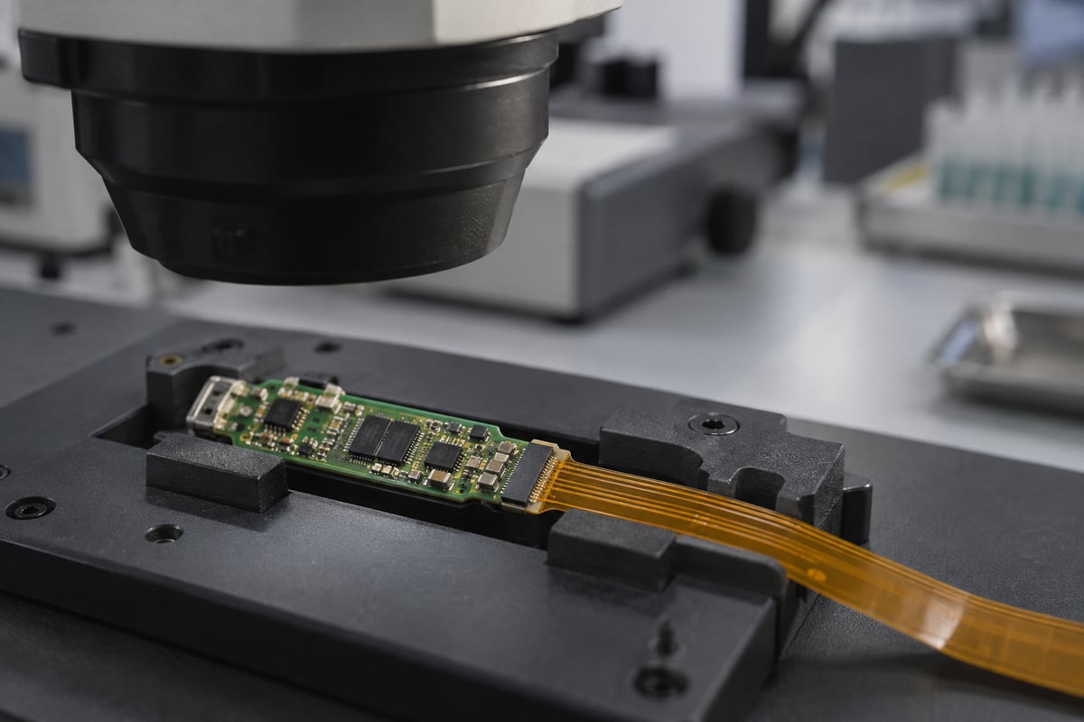
Why Choose BestFPC for Your Endoscope PCB?
For an endoscope PCB, compact dimensions, flex construction and assembly quality must work together. BestFPC combines engineering support with in-house FPC and PCBA manufacturing to help turn your approved design into prototypes and assemblies for evaluation.
- DFM support from experienced engineers: Our FPC and PCBA engineers with 20 years of experience provide DFM pre-review reports and process recommendations. For an endoscope board, the review can focus on the proposed stackup, bend transitions, component support and assembly access, helping identify manufacturing concerns before fabrication.
- Integrated fabrication, sourcing and assembly: For projects using flex circuits or rigid flex circuits for medical devices, BestFPC coordinates fabrication, component procurement, PCBA assembly and agreed testing. BOM optimization recommendations are submitted for your review, so component or assembly changes can be assessed against the camera interface and mechanical requirements before approval.
- Prototype and small-batch support: Build evaluation quantities before committing to volume production. This gives your engineering team boards and assemblies for checking fit, imaging operation and the intended bend arrangement, with an opportunity to refine the design before scaling up.
- Quality systems relevant to medical projects: BestFPC holds ISO 9001 and ISO 13485 certifications, supporting a structured approach to quality management for medical electronics manufacturing. Inspection requirements, test coverage and acceptance criteria are agreed for the specific PCB assembly; finished-device validation remains with the medical device manufacturer.
- Batch traceability and production visibility: Our digital workshop supports tracking of material and product batches, production cycles and job progress. This helps connect an evaluation result or quality issue to the relevant build and gives your team visibility when planning prototype reviews or subsequent orders.
Together, these capabilities help you address manufacturing risks early and carry an approved endoscope PCB design through fabrication and assembly. To discuss your project, email sales@bestfpc.com with your Gerber files, board drawing, quantity and BOM if assembly is required. Include the intended bend arrangement and testing needs so BestFPC can review feasibility and prepare a quotation.
FAQs About Endoscope PCB
Does a smaller PCB automatically allow a thinner endoscope?
No. Optics, working channels, articulation parts and the assembled electronics also occupy space. Reducing the board outline helps only if the PCB assembly is a limiting feature of the proposed enclosure.
Can an endoscope PCB replace a board in any scope model?
No. Mechanical fit is only one condition. Electrical interfaces, pin assignments, camera compatibility and system configuration must also match. A custom fabrication service should not be treated as a source of universally interchangeable repair boards.
Can a stiffener replace the rigid section of a rigid-flex PCB?
A stiffener can provide local mechanical support, but it does not provide the additional electrical routing of a rigid multilayer section. Whether it is sufficient depends on what that section must do.
Is conformal coating enough to make the assembly waterproof?
Coating alone does not establish a waterproof assembly. Connectors, exposed contacts, housing seals and the specified exposure conditions still matter. Protection needs to be evaluated in the completed assembly.
Can prototype results be used to approve volume production?
Prototype results are useful only within the construction and conditions tested. Changes to materials, copper, stackup, assembly or mechanical routing may require further evaluation. Keep the production revision aligned with the qualified configuration.
Ready to move your endoscope PCB toward prototyping? Send your Gerber files, board drawing and target quantity to BestFPC at sales@bestfpc.com for a manufacturing review and quotation. Include the intended bend arrangement and a BOM if assembly is required, so we can assess the proposed build against your project requirements.


.png)
.png)
.png)
.png)

.png)