


 2026-10-21

 BEST
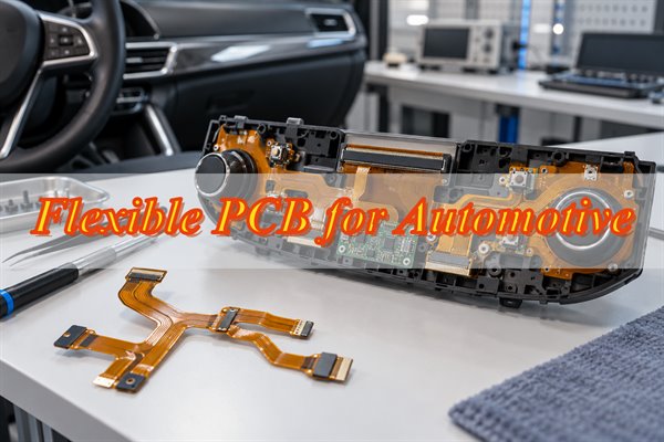
Flexible PCB for automotive applications provides compact, lightweight electrical connections in EV battery monitoring systems, ADAS cameras, automotive displays, and interior controls. Its flexible construction allows circuits to fit curved housings and narrow installation spaces where conventional wiring or rigid PCBs may be impractical.
However, battery sensing, camera interfaces, and display modules require different FPC structures, materials, and connection methods. BestFPC manufactures custom single-sided, double-sided, and multilayer flexible PCBs to match these automotive requirements, with DFM review and assembly support.
Where Are Flexible PCBs Used in Automotive Applications?
Flexible PCBs connect electronic components in vehicles where space, weight, and installation geometry make conventional wiring less practical. Their functions vary across automotive systems, from low-current battery sensing to high-speed camera interfaces.
| Automotive Application | FPC Function | Manufacturing Requirements |
|---|---|---|
| EV Battery Management Systems | Cell voltage and temperature sensing connections | Electrical insulation, custom circuit outlines, precise sensing contacts |
| ADAS Cameras | Image sensor and camera board interconnections | Fine-line routing, signal integrity, connector accuracy |
| Radar and Sensor Modules | Internal sensor-to-board connections | Compact construction, dimensional accuracy, signal routing |
| Dashboard and Infotainment Displays | Display, touch interface, and control connections | Thin construction, accurate connector alignment, installation bending |
| Automotive LED Lighting | LED and lighting control interconnections | Current capacity, temperature compatibility, mechanical reinforcement |
| Steering Wheel and Interior Controls | Switch, sensor, and control module connections | Flexible installation, reinforced contacts, vibration resistance |
The actual manufacturing requirements become clearer when examining three common automotive applications: EV battery monitoring, ADAS camera modules, and automotive displays.
How Are Flexible PCBs Used in EV Battery Monitoring Systems?
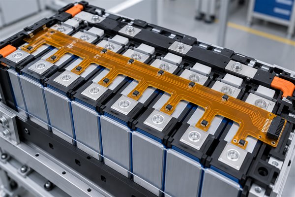
EV battery monitoring FPCs connect cell voltage sensing points and temperature sensors to battery monitoring electronics. They can replace multiple individual sensing wires with a shaped circuit that follows the battery module layout.
In cell contacting assemblies, the FPC may have multiple branches extending to designated sensing locations. Each connection must align with the battery module without excessive mechanical stress.
- Electrical Insulation: Copper spacing and dielectric materials must satisfy the battery system's electrical and insulation requirements.
- Sensing Connections: Contact dimensions and connection resistance must support reliable voltage and temperature measurement.
- Custom Outlines: Branches, slots, and mounting features must match cell positions and assembly clearances.
- Mechanical Stability: Sensing branches and terminations must withstand the specified vibration, temperature changes, and installation stresses.
A common manufacturing concern is stress concentration near narrow branches and connection points. Incorrect stiffener placement or insufficient installation clearance can place tension on the circuit during assembly.
For battery applications, the FPC normally carries low-current monitoring signals rather than the main battery power current. High-current paths require separately engineered conductors and electrical protection.
What Do ADAS Cameras and Sensors Require from Flexible PCBs?
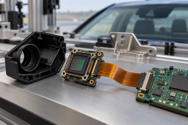
ADAS camera FPCs require compact routing, accurate connector geometry, and stable signal transmission. Camera housings often contain closely spaced image sensors and processing electronics, leaving limited room for conventional cable connections.
Four manufacturing requirements deserve particular attention:
-
High-Speed Signal Routing: Camera interfaces may require controlled impedance, differential pairs, and defined signal return paths.
-
Fine-Line Circuits: Narrow traces and close spacing support high-density interconnections within compact modules.
-
Connector Precision: Contact pitch, exposed pad dimensions, and stiffener thickness must match the mating connector.
-
Bending Clearance: Vias, solder joints, and abrupt reinforcement transitions should be kept away from stressed bending areas where practical.
For example, an FPC connecting an image sensor to a nearby processing board may be folded during assembly. The installed bend must not pull against the connector or place excessive stress on its termination.
When manufacturing a flexible PCB for automotive camera modules, signal routing and connector accuracy are often more critical than minimizing board thickness alone.
How Are Flexible PCBs Used in Automotive Displays and Interior Controls?
Automotive flexible PCBs connect display panels, touch interfaces, switches, and control circuits within dashboards and interior assemblies. Their thin construction accommodates curved surfaces and folded connections behind screens.
In instrument clusters and infotainment systems, an FPC may carry display signals, touch inputs, or backlight connections. Interior control modules use flexible circuits to connect buttons and sensors positioned at different angles.
The manufacturing focus is primarily on:
-
Connector Contact Dimensions: Exposed contact length, pitch, and reinforced thickness must match the connector specification.
-
Installation Geometry: Circuit outlines and bend positions must fit the dashboard or control housing.
-
Localized Stiffeners: Reinforcement supports connector tails and component mounting areas without restricting the intended flexible regions.
-
Assembly Compatibility: Accurate pad positions and stable mounting areas support connector installation and component assembly.
A display FPC that fits when flat may still experience connector stress after installation. The approved drawing should therefore specify the installed bend location, contact geometry, and reinforcement requirements.
For curved displays and interior controls, custom FPC construction allows the electrical connection to follow the product's mechanical arrangement rather than relying on a standard cable shape.
Which Flexible PCB Structures Are Suitable for Automotive Applications?
Single-sided and double-sided FPCs suit many automotive sensing and control connections. Multilayer FPCs are more appropriate when routing density or electrical requirements exceed the capabilities of simpler constructions.
| PCB Structure | Automotive Applications | Advantages | Limitations |
|---|---|---|---|
| Single-Sided Flexible PCB | Basic sensors, switches, simple lighting connections | Thin construction, relatively simple fabrication | Limited routing density |
| Double-Sided Flexible PCB | Display interfaces, sensor and control modules | More routing options with interlayer connections | Additional manufacturing complexity and reduced flexibility compared with similar single-layer constructions |
| Multilayer Flexible PCB | Compact camera modules, high-density electronic interconnections | Higher routing density and additional signal/ground arrangements | Increased thickness, cost, and bending restrictions |
| Rigid-Flex PCB | Compact electronic assemblies requiring rigid mounting areas | Combines component support with flexible interconnections | More complex construction and manufacturing |
Rigid-flex PCBs are a separate construction from fully flexible PCBs, but they may be considered when components require rigid mounting sections.
A multilayer flexible PCB for automotive electronics should be selected when its additional routing layers provide a clear electrical or mechanical benefit. Otherwise, a simpler FPC may offer lower cost and greater flexibility.
What Material, Bend, and Connector Requirements Should You Consider?
Polyimide materials, copper construction, bend radius, and connector reinforcement directly affect how an automotive FPC performs after installation. Material specifications should reflect the actual operating conditions rather than using one standard stackup for every application.
-
Polyimide Substrate: Provides a flexible insulating base with good thermal stability. Material grade and thickness must suit the specified operating environment.
-
Copper Foil: Rolled-annealed (RA) copper is often considered for repeated bending. Suitable electrodeposited (ED) copper may be used for static installations, depending on the complete construction.
-
Coverlay: Protects copper traces and leaves connection pads exposed. Its openings and edges must be positioned to avoid unnecessary stress.
-
Finished Thickness: Copper layers, PI thickness, adhesive, and coverlay determine the finished construction and influence its bending behavior.
-
Bend Radius: Must account for the circuit stackup, bending direction, and whether the FPC is installed in a fixed position or subjected to repeated movement.
-
Connector Stiffeners: PI or other approved reinforcement materials provide localized support. The finished contact-tail thickness must match the mating connector.
Surface finishes also affect mechanical performance. Conventional nickel-bearing ENIG should generally be kept away from repeatedly bending regions, unless the construction has been specifically qualified for that use.
For a flexible PCB for automotive applications, bending specifications should identify the exact bend location, radius, direction, and expected movement. This allows manufacturing feasibility to be assessed against the actual circuit construction.
How Does BestFPC Manufacture Custom Automotive Flexible PCBs?
BestFPC manufactures automotive FPCs using customer-approved circuit files, material specifications, and mechanical drawings. Customization covers circuit patterns, stackups, shaped outlines, coverlay, stiffeners, surface finishes, and SMT assembly where required.
The manufacturing approach is adjusted according to the application rather than treating every automotive FPC as the same construction.
Step 1: Manufacturing File and DFM Review
BestFPC reviews the supplied Gerber files, stackup, material specifications, and fabrication drawings. Particular attention is given to bend areas, trace spacing, connector dimensions, coverlay openings, and stiffener positions.
For branched battery sensing circuits, the review includes narrow sections and connection locations. Camera and display FPCs require particular attention to routing density and reinforced connector geometry.
Step 2: Circuit Fabrication and Reinforcement
Approved circuit patterns are transferred to the selected flexible laminate and fabricated through the applicable imaging, etching, plating, and lamination processes.
Coverlay openings, custom outlines, and stiffeners are processed according to the released drawing. Reinforcement boundaries and contact-tail thickness must remain consistent with the intended installation and connector requirements.
Step 3: Electrical Inspection and Assembly
Bare FPCs are inspected against the agreed manufacturing requirements. Electrical testing is used to identify open and short circuits.
For assembled circuits, BestFPC supports SMT component mounting. Thin flexible panels may require dedicated carriers or fixtures to maintain stability during solder paste printing, placement, and reflow.
BestFPC Flexible PCB Manufacturing Capabilities
| Manufacturing Parameter | Reference Capability | Applicable Conditions |
|---|---|---|
| FPC Layer Count | 1–4 layers | Standard all-flex construction; higher layer counts by review |
| Finished Board Thickness | 0.06–0.60 mm | Depends on the approved stackup |
| Inner-Layer Line / Space | 3/3 mil (0.076/0.076 mm) | 18 μm finished copper; before manufacturing compensation |
| Outer-Layer Line / Space | 3.5/3.5 mil (0.089/0.089 mm) | 18 μm finished copper; before manufacturing compensation |
| Base Materials | Adhesive and adhesiveless PI | Material grade and thickness selected by project |
| Copper Options | 0.33 oz, 0.5 oz, 1 oz; selected 2 oz constructions | Depends on laminate, copper thickness, and bend requirements |
| Surface Finishes | ENIG, plated gold, OSP, immersion tin | Selected for the required contact and soldering applications |
| Stiffeners | PI; other constructions by review | Position, thickness, and adhesive specified on the drawing |
| Controlled Impedance | Project-specific; ±10% reference tolerance | Subject to approved stackup and manufacturing review |
These parameters are reference capabilities, not guaranteed combinations. Fine-line requirements, thicker copper, multilayer construction, and bending specifications must be evaluated together before production.
What Affects Automotive Flexible PCB Manufacturing Costs?
Layer count, materials, circuit density, board geometry, and assembly requirements determine automotive FPC manufacturing costs. Two circuits with similar dimensions can have different prices because their manufacturing requirements are different.
| Cost Factor | Manufacturing Impact |
|---|---|
| Layer Count | Additional layers increase fabrication and lamination complexity |
| Material Selection | Specialized polyimide laminates and copper constructions may increase material costs |
| Circuit Density | Fine traces, tight spacing, and close tolerances can increase processing difficulty |
| Board Outline | Long, branched, or irregular shapes may reduce manufacturing panel utilization |
| Stiffeners and Surface Finishes | Additional materials and processing affect unit costs |
| SMT Assembly | Components, connector mounting, and dedicated fixtures increase assembly operations |
| Order Quantity | Tooling and setup costs are distributed differently across order volumes |
An EV battery sensing FPC may be expensive because of its length and irregular shape, while a compact ADAS camera FPC may cost more because of fine-line routing and connector precision.
Providing the intended order quantity and complete manufacturing specifications allows BestFPC to evaluate the actual cost of the required construction.
Why Choose BestFPC for Automotive Flexible PCB Manufacturing?
BestFPC combines more than 20 years of FPC manufacturing experience with custom fabrication, free DFM review, and flexible ordering options. These services help automotive electronics customers address manufacturing feasibility before placing an order.
-
20+ Years of FPC Manufacturing Experience: Custom flexible circuit experience supports projects involving complex outlines, multilayer constructions, and reinforced connection areas.
-
Free DFM Review Before Production: Customers receive manufacturing feedback on critical dimensions, bend areas, materials, and connector details before fabrication release.
-
No Minimum Order Quantity: Prototype quantities can be ordered without a fixed MOQ, allowing customers to evaluate custom constructions before committing to larger volumes.
-
Fabrication and Assembly Coordination: Bare-board manufacturing and SMT assembly can be coordinated within one project, reducing communication gaps between fabrication and component mounting.
-
Quality Documentation: Manufacturing and inspection requirements can be defined with the project, including applicable electrical testing, traceability, and customer-specified acceptance criteria.
For automotive procurement, quality-system certifications, manufacturing records, and any required customer approvals should be verified against the actual production scope. Certification alone does not mean every FPC has been individually qualified for automotive use.
BestFPC manufactures flexible circuits according to approved customer specifications, helping OEMs and automotive electronics suppliers obtain application-specific FPCs without relying on standard, off-the-shelf constructions.
What Do You Need to Request an Automotive Flexible PCB Quote?
A complete RFQ should identify the circuit construction, mechanical installation, electrical requirements, and expected quantity. These details allow BestFPC to review manufacturing feasibility and provide a project-specific quotation.
-
Gerber Files: Complete circuit artwork and layer information.
-
Fabrication Drawings: Outline, holes, slots, dimensions, and critical tolerances.
-
Material Specifications: Layer count, PI materials, copper construction, coverlay, and surface finish.
-
Bending Requirements: Bend locations, radius, direction, and static or dynamic movement conditions.
-
Connector Details: Contact dimensions, stiffener thickness, connector part number, and mating requirements.
-
Assembly Files: BOM, component placement files, and assembly drawings if SMT assembly is required.
-
Purchasing Requirements: Prototype or production quantity, delivery destination, schedule, and agreed quality documentation.
For a flexible PCB for automotive applications, include the intended equipment and operating conditions, especially where insulation, high-speed signals, or mechanical movement affect the circuit.
Send your Gerber files and project specifications to sales@bestfpc.com for a free DFM review and customized quotation.
FAQs About Flexible PCB for Automotive Applications
Q1: What is the difference between an automotive FPC and an FFC cable?
A1: An FPC is a patterned flexible circuit that can incorporate custom copper routing, multiple layers, pads, and local reinforcement. An FFC typically uses parallel conductors laminated within an insulating film. They are not automatically interchangeable. Connector dimensions, electrical requirements, conductor arrangements, and installation geometry must be checked before replacing one with the other.
Q2: Should automotive FPC connector contacts use ENIG or hard gold?
A2: The appropriate finish depends on the connector's contact arrangement and mating requirements. Hard gold is commonly considered for contacts exposed to repeated insertion and sliding wear, while ENIG may be suitable for applications that do not require the same contact wear resistance. Gold thickness, mating cycles, contact force, and the connector manufacturer's specifications should be confirmed before production.
Q3: Can adhesive be used to secure an automotive FPC inside a housing?
A3: Yes. Pressure-sensitive adhesives can secure suitable FPC sections to internal housings or mounting surfaces. However, adhesive selection must account for operating temperature, surface material, vibration, and installation conditions. Adhesive should not restrict an intended dynamic bending area or introduce excessive stress near connector terminations.
Q4: Is EMI shielding required for every automotive flexible PCB?
A4: No. Shielding depends on the signal characteristics, operating environment, and applicable electromagnetic compatibility requirements. Sensitive interfaces may use shielding films, reference conductors, or suitable grounding arrangements. These features can affect thickness and flexibility, so the shielding requirement should be established before finalizing the FPC construction.
Q5: Does AEC-Q100 certification apply to automotive flexible PCBs?
A5: AEC-Q100 applies to integrated circuits, not bare flexible PCBs. Flexible circuit qualification may reference IPC-6013 and customer-specific requirements, while automotive manufacturing quality systems may be assessed separately. The applicable performance class, acceptance criteria, and qualification requirements should be specified for the actual product and purchasing arrangement.
Q6: Are PPAP documents required for every automotive FPC order?
A6: Not automatically. Production Part Approval Process (PPAP) requirements depend on the automotive customer's supplier qualification and purchasing procedures. Where applicable, the required submission level, records, samples, and approval responsibilities should be agreed before production. A prototype order does not automatically include a complete PPAP package.
Q7: Can customers supply their own components for automotive FPC assembly?
A7: Yes, subject to the agreed assembly arrangement. BestFPC supports customer-supplied component options for suitable projects. Component part numbers, quantities, packaging conditions, and assembly documentation should be confirmed before production. Connector compatibility and handling requirements are particularly relevant for thin flexible circuits.
Q8: How are irregular automotive FPC outlines and branches controlled during manufacturing?
A8: Custom outlines are fabricated according to the approved mechanical drawing. Critical dimensions, reference datums, narrow branches, and connector locations should be clearly identified, especially where several circuit branches must align with fixed mounting points. Inspection requirements are then agreed against the released drawing and manufacturing process.
Q9: Do material or manufacturing process changes require customer approval?
A9: Changes affecting approved materials, copper construction, stackup, surface finish, or critical dimensions should follow the customer's agreed change-control process. An alternative material should not be treated as automatically equivalent, even if its basic specifications appear similar. Additional evaluation may be required when the change affects bending performance, electrical properties, or product qualification.
Q10: How should thin automotive FPCs be protected during shipping?
A10: Packaging should prevent creases, excessive bending, contact damage, contamination, and mechanical pressure. Thin FPCs may require support sheets, trays, or other protective packaging appropriate to their shape and exposed contacts. The packaging method should also account for the board's finished dimensions, quantity, and any customer-specified handling or traceability requirements.
Conclusion
Flexible PCB for automotive applications provides compact electrical connections in EV battery monitoring systems, ADAS cameras, vehicle displays, and interior electronics. Reliable manufacturing depends on selecting the correct FPC structure, materials, bend specifications, and connector details for each application.
BestFPC offers custom flexible PCB fabrication, free DFM review, SMT assembly, and manufacturing support for automotive electronics. Whether your project requires an OEM prototype, custom multilayer FPC, or volume production, send your Gerber files and requirements to sales@bestfpc.com for technical review and a customized quotation.


.png)
.png)
.png)
.png)

.png)