


 2026-10-21

 BEST
A flexible PCB for wearable electronics must fit where conventional circuit boards and wiring often cannot. Inside a smartwatch, fitness tracker, or smart ring, even a small increase in circuit thickness can interfere with a battery, sensor, or enclosure. Poorly positioned bends and unsupported components can also turn a functional prototype into an unreliable product.
BestFPC manufactures custom flexible PCBs and provides FPC assembly services for wearable electronics, from thin sensor interconnections to multilayer FPC assemblies. Backed by 20+ years of experience, we support prototyping, DFM review, component assembly, and volume production.
What Types of Wearable Electronics Use Custom Flexible PCBs?
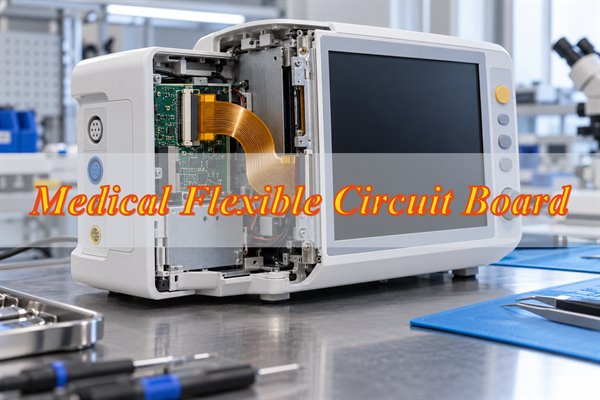
Flexible PCBs are widely used in smartwatches, fitness trackers, smart rings, smart glasses, wireless earbuds, and wearable health monitoring devices. They connect electronic components within compact or curved housings while reducing the space required for conventional wiring.
- Smartwatches: Connect displays, batteries, sensors, and control boards. Thin FPCs and reinforced connector areas help accommodate components inside compact watch housings.
- Fitness Trackers: Connect motion sensors, optical heart-rate sensors, and battery modules. Double-sided or multilayer FPCs support compact routing, while controlled bend areas reduce mechanical stress.
- Smart Rings: Connect miniature sensors and electronic modules inside narrow, curved enclosures. Thin FPCs require precise outlines, compact routing, and tight dimensional control.
- Smart Glasses: Connect cameras, displays, microphones, and electronic modules located in different parts of the frame. Multilayer FPCs can accommodate narrow installation paths and complex connections.
- Wireless Earbuds: Connect microphones, charging contacts, and audio components. Miniature FPCs help fit multiple electrical connections into limited space while maintaining reliable contact interfaces.
- Wearable Health Monitors: Connect biosensors, electrodes, and control electronics. Thin FPCs support low-profile construction, with mechanical protection and environmental requirements determined by the intended application.
The main distinction is whether the FPC remains fixed after installation or bends repeatedly during use. This determines how the copper, stackup, bending areas, and reliability tests should be specified.
Which Flexible PCB Structures Are Suitable for Wearable Electronics?
Double-sided flexible PCBs are a practical choice for many compact sensor connections. Multilayer constructions are useful when routing density or electrical requirements exceed what simpler structures can accommodate.
|
FPC Structure |
Best Suited For |
Advantages |
Considerations |
|---|---|---|---|
|
Single-Sided FPC |
Simple sensors, charging interfaces, low-density connections |
One copper layer, straightforward fabrication, thin construction |
Limited routing flexibility |
|
Double-Sided FPC |
Fitness trackers, smartwatch interconnections, compact sensor modules |
Two routing layers, greater connection density |
Via locations and bending regions require careful planning |
|
Multilayer FPC |
Smart glasses, complex sensing modules, dense interconnections |
Additional routing layers for signal and power connections |
Increased thickness and bending stiffness |
Choose the FPC structure based on routing requirements, available installation space, and bending conditions. A simpler construction is generally preferable when it meets the device's electrical and mechanical requirements.
What Materials and Stackups Are Suitable for Wearable Flexible PCBs?
Polyimide (PI) substrates, suitable copper foil, flexible coverlay, and localized stiffeners are commonly used in wearable FPCs. The best combination depends on the required thickness, bending conditions, and component layout.
- Polyimide (PI) Substrate: Provides flexibility and thermal resistance. Thin PI films suit compact wearable circuits, but the thickness must also provide adequate handling strength.
- RA vs. ED Copper: Rolled annealed (RA) copper is often preferred for repeated bending, while electrodeposited (ED) copper is widely used in static-flex applications. The complete construction must be qualified for the intended movement.
- Adhesiveless vs. Adhesive-Based Laminates: Adhesiveless laminates help reduce stackup thickness by eliminating the bonding layer between the copper and PI core. Adhesive-based laminates remain suitable for many circuits with less demanding thickness or bending requirements.
- Polyimide Coverlay: Protects the copper traces while leaving solder pads and connector contacts exposed. Its thickness and openings must accommodate the assembly requirements.
- PI or FR-4 Stiffeners: Reinforce connectors and component-mounting areas. The selected thickness must match the connector and mechanical support requirements.
For wearable FPC manufacturing, specify the finished thickness of both the flexible section and any reinforced connector areas. These dimensions help ensure the circuit fits the enclosure and mating components.
How Do Bending Areas and Component Placement Affect Wearable FPC Manufacturing?
Bending areas and component placement affect wearable FPC manufacturing by determining where mechanical stress occurs. Concentrated stress around vias, solder joints, conductor transitions, and stiffener edges can cause copper cracking or connection failures.
- Bend Radius: Define the minimum installed radius and whether bending occurs once during assembly or repeatedly during use. Dynamic-flex applications require a separate assessment of movement and fatigue life.
- Copper Routing: Keep conductors smooth through bending regions. Avoid sharp transitions, sudden changes in trace width, and unnecessary copper features that concentrate stress.
- Via Locations: Keep plated through-holes outside active bending areas wherever possible. Copper around plated holes is more vulnerable to fatigue under repeated movement.
- Component Placement: Position sensors, ICs, and connectors on supported sections. Solder joints should not be subjected to repeated bending.
- Stiffener Boundaries: Reinforcement must support the component without creating excessive stress at the transition between stiffened and flexible sections.
- Enclosure Clearance: Check the installed circuit against batteries, housing walls, mounting features, and other components.
A fitness tracker with a fixed internal bend does not require the same construction as a wearable strap that flexes with every movement.
BestFPC reviews customer-provided fabrication files for bend-area clearance, reinforcement placement, and manufacturing feasibility. Where changes are recommended, the final specifications remain subject to customer approval.
What Manufacturing Capabilities Matter for Custom Wearable FPCs?
Thin finished boards, fine-line circuits, precise outlines, and reliable connector reinforcement are particularly relevant to wearable FPC manufacturing. A circuit must meet its electrical requirements while fitting the space allocated inside the device.
|
Manufacturing Parameter |
Reference Capability |
|---|---|
|
Flexible PCB Layer Count |
1–4 layers |
|
Finished Board Thickness |
0.06–0.60 mm |
|
Inner-Layer Line Width / Spacing |
3/3 mil (0.076/0.076 mm) |
|
Outer-Layer Line Width / Spacing |
3.5/3.5 mil (0.089/0.089 mm) |
|
Adhesive-Based PI Core |
0.5, 1, 2 mil |
|
Adhesiveless PI Core |
0.5, 1, 2, 3 mil |
|
Adhesive-Based Core Copper |
0.33, 0.5, 1 oz |
|
Adhesiveless Core Copper |
0.33, 0.5, 1, 2 oz |
|
PI Stiffener Thickness |
3, 5, 7, 9 mil |
|
Controlled Impedance Tolerance |
±10% |
|
Laser Profile Tolerance |
±0.10 mm standard; ±0.05 mm special |
|
Surface Finish |
ENIG, plated gold, OSP, immersion tin |
How Are Flexible PCBs Assembled for Wearable Electronics?
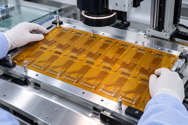
Wearable FPC assembly uses SMT processes with additional mechanical support to prevent deformation during solder paste printing, component placement, and reflow. Thin flexible circuits can move or warp during processing, affecting placement accuracy and solder joint quality.
Step 1: Review the Assembly Files
Check the BOM, component footprints, connector orientation, and placement data against the released fabrication files. Component positions must provide enough clearance from bending areas and stiffener boundaries.
Step 2: Secure the FPC During Assembly
A suitable carrier or fixture keeps the flexible circuit flat and stable. Support is particularly useful beneath miniature sensors, fine-pitch ICs, and connectors where movement could affect solder paste printing or placement accuracy.
Step 3: Print Solder Paste and Place Components
Solder paste is deposited through a stencil before automated equipment places the specified components. Stable fiducial positioning and appropriate paste deposits help control placement and soldering defects.
Step 4: Complete Reflow Soldering
The reflow profile is selected according to the solder paste, component requirements, and FPC construction. The circuit must remain adequately supported throughout heating and cooling.
Step 5: Inspect and Verify the Assembly
Check solder joints, component orientation, alignment, and electrical connections. AOI, SPI, X-ray, and functional testing are applied as required by the component packages and agreed inspection scope.
The finished assembly must also fit the intended enclosure. A correctly soldered FPC can still fail a mechanical fit check if its connector height, stiffener thickness, or component clearance differs from the approved dimensions.
How Are Wearable Flexible PCB Assemblies Tested for Reliability?
Wearable FPC assemblies require electrical, mechanical, and functional verification. Testing should cover both manufacturing defects and the conditions the circuit will experience inside the finished device.
- Electrical Testing: Check bare FPCs for open circuits and shorts before assembly. This confirms circuit connectivity but not mechanical durability.
- SMT Inspection: Use visual inspection and AOI for accessible components and solder joints. X-ray may be required for hidden solder connections.
- Functional Testing: Verify power connections, sensor communication, and other specified functions after assembly.
- Bending Tests: Test representative samples at the required bend radius and cycle count. Monitor electrical continuity to identify cracking or connection failures caused by movement.
- Environmental Testing: Evaluate temperature, humidity, or sweat exposure where relevant to the application. Test conditions must match the product's operating environment and protection requirements.
Define the acceptance criteria before testing, including the bend radius, cycle count, electrical limits, and functional requirements. A passed electrical test alone cannot guarantee long-term bending reliability.
What Affects Wearable FPC Manufacturing and Assembly Costs and Lead Time?
Layer count, materials, fine-line requirements, assembly complexity, and component availability have the greatest influence on wearable FPC production planning. Some costs are fixed during initial setup, while others change with the order quantity.
- Circuit Construction: Additional layers, dense routing, and special via structures can increase fabrication steps. Use the simplest construction that meets the approved electrical requirements.
- Material Availability: Standard PI laminates are generally easier to source than uncommon material combinations. Check material availability before committing to prototype or production dates.
- Board Geometry: Narrow branches, multiple stiffeners, and complex outlines may require additional tooling or handling. Review manufacturability before freezing the mechanical drawing.
- Component Sourcing: Miniature ICs, sensors, and specialized connectors can affect the assembly schedule. Confirm approved part numbers and purchasing requirements early.
- Assembly Preparation: Custom carriers, double-sided mounting, fine-pitch components, and additional inspection requirements can increase setup work.
- Order Quantity: Prototype and volume orders differ in setup allocation, material purchasing, panel utilization, and production scheduling.
For projects moving from prototypes to volume production, use the approved prototype revision as the basis for the production review. Material changes, connector substitutions, or revised bending requirements should be evaluated before the next build.
Why Choose BestFPC for Wearable FPC Manufacturing and Assembly?
BestFPC supports both bare flexible circuit manufacturing and populated FPC assembly, helping wearable electronics customers coordinate fabrication and assembly requirements through one supplier.
- 20+ Years of FPC Manufacturing Experience: Support for custom flexible circuit constructions, including thin circuits, multilayer routing, and reinforced connection areas.
- Custom Manufacturing to Your Specifications: Options for PI materials, copper constructions, coverlay, board outlines, and localized stiffeners based on the approved fabrication files.
- Free DFM Review: Engineering feedback on manufacturability, bend-area risks, tolerances, and connector reinforcement before fabrication.
- FPC Manufacturing and SMT Assembly: Bare-board production and component assembly support, with component sourcing arrangements based on the approved BOM.
- Prototype and Volume Production: No MOQ for eligible bare FPC orders, with assembly quantities and production schedules evaluated against project requirements.
You can submit the same set of approved manufacturing and assembly requirements for a coordinated project review, reducing the risk of mismatched fabrication, component, and mechanical specifications.
Case Analysis: Custom Flexible PCB Manufacturing and Assembly for a Fitness Tracker
Project Background
A compact fitness tracker needs a flexible circuit to connect its optical sensor, control electronics, and rechargeable battery. Space inside the curved enclosure is limited, and separate wiring would add bulk and complicate assembly.
Requirements & Challenges
- Limited Installation Space: The FPC must fit around internal components without excessive thickness or sharp folds.
- Reliable Sensor Connections: Fine traces and solder joints must remain stable after installation.
- Bend-Area Protection: Conductors, vias, and component pads must be positioned to avoid concentrated mechanical stress.
- SMT Assembly Stability: The thin FPC requires mechanical support during solder paste printing, miniature component placement, and reflow.
BestFPC's Manufacturing & Assembly Solution
- FPC Construction: Evaluate a thin, double-sided PI circuit with coverlay protection to accommodate the required sensor and power connections.
- Bending and Reinforcement: Review bend locations and add localized stiffeners beneath connectors and component-mounting areas.
- Manufacturing Review: Check the approved stackup, copper routing, finished thickness, and outline tolerances against the enclosure drawing.
- SMT Assembly: Use suitable carrier fixtures to maintain FPC flatness during component placement and soldering.
- Quality Verification: Define electrical testing, solder joint inspection, functional testing, and enclosure-fit checks for prototype approval.
Output & Results
For this reference application, the intended output is a double-sided PI flexible PCB assembly with supported component areas and defined bending regions, together with the fabrication specifications and agreed inspection requirements.
Prototype acceptance would require:
- Electrical continuity and isolation tests meeting the approved limits.
- SMT components and solder joints meeting the agreed inspection criteria.
- Finished FPC dimensions and connector interfaces fitting the enclosure.
- Sensor and power connections passing the specified functional tests.
- Bending verification where repeated movement is part of normal operation.
This is a reference application, not a verified completed customer project. Manufacturing yield, test measurements, and delivery results must be confirmed through an actual prototype build.
What Files Are Needed for a Custom Wearable FPC Manufacturing and Assembly Quote?
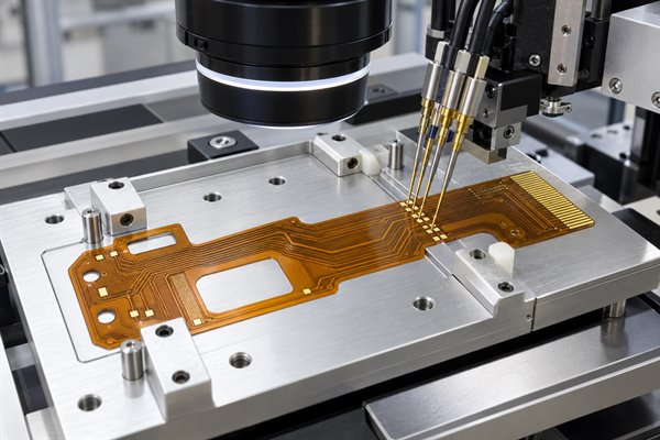
Send the fabrication data, mechanical requirements, and required quantity for a bare wearable FPC quotation. Add the BOM and assembly files when component mounting is needed.
- Gerber or ODB++ Files: Copper layers, drill data, coverlay openings, and board outline.
- Fabrication Specifications: Layer count, stackup, materials, copper thickness, surface finish, and required tolerances.
- Mechanical Drawings: Bend locations, minimum bend radius, stiffener details, connector positions, and installation dimensions.
- Assembly Files: BOM, pick-and-place data, assembly drawings, component orientation, and polarity information.
- Testing Requirements: Electrical testing, inspection criteria, functional checks, and any required mechanical qualification.
- Order Details: Prototype quantity, expected production volume, target delivery date, and delivery destination.
For wearable products exposed to repeated movement, provide the expected bending conditions. A defined bend radius and cycle requirement allow the proposed construction to be assessed more accurately.
FAQs About Flexible PCBs for Wearable Electronics
Q1: Can a flexible PCB stretch with wearable fabric?
A1: Conventional flexible PCBs can bend but do not stretch like elastic fabric. Products requiring significant stretching need a suitable stretchable circuit construction or mechanical arrangement that prevents excessive strain on the conductors.
Q2: Are flexible PCBs waterproof without additional protection?
A2: No. A flexible PCB is not inherently waterproof. Devices exposed to sweat or water may require enclosure sealing, protective coatings, or encapsulation validated for the intended environment.
Q3: Can a flexible PCB come into direct contact with human skin?
A3: Direct skin contact requires an assessment of the exposed materials and intended use. Standard FPC materials should not be assumed suitable for prolonged skin contact without appropriate evaluation.
Q4: Can wearable FPCs use ZIF connectors?
A4: Yes. ZIF connectors provide detachable connections for flexible circuits. The contact pitch, insertion thickness, stiffener dimensions, and surface finish must match the connector specification.
Q5: Can flexible PCB traces carry battery charging current?
A5: Yes, provided the conductor width, copper thickness, voltage drop, and temperature rise meet the electrical requirements. Narrow power traces should be checked against the expected current.
Q6: Is ENIG suitable for areas that bend repeatedly?
A6: ENIG is widely used for solder pads and contacts, but its nickel layer can be a concern in dynamic bending regions. Keep nickel-bearing finishes outside repeatedly flexed areas where practical, or qualify the construction through testing.
Q7: Can shielding be added to a wearable flexible PCB?
A7: Yes. Grounding structures and compatible shielding films can help control electromagnetic interference. The selected approach must account for added thickness, flexibility, grounding, and signal performance.
Q8: Can a flexible PCB include an antenna for wireless wearable devices?
A8: Yes. An FPC antenna can be integrated into a wearable product, but the installed shape, enclosure materials, nearby components, and antenna matching can affect RF performance.
Q9: Can one FPC design be used across several wearable product models?
A9: Yes, if the models share compatible electrical interfaces, mechanical dimensions, connectors, and operating conditions. Different enclosure shapes or bending requirements may require separate validation.
Q10: How can component substitutions be controlled during wearable FPC assembly?
A10: Use an approved BOM with defined manufacturer part numbers. Any proposed substitution should receive customer approval after checking electrical characteristics, physical dimensions, and assembly compatibility.
Conclusion
A reliable flexible PCB for wearable electronics must fit the enclosure, support the electronic components, and withstand the mechanical conditions of the finished device. Choosing the right structure, materials, bend configuration, and assembly process helps reduce manufacturing problems before production.
BestFPC provides custom flexible PCB manufacturing and assembly for wearable electronics, with 20+ years of experience, free DFM review, and support from prototypes to volume production. Send your Gerber files, mechanical drawings, BOM, and required quantities to sales@bestfpc.com for a manufacturing review and custom quotation.


.png)
.png)
.png)
.png)

.png)