


 2026-10-27

 BEST
A custom FPC cable should fit the enclosure, mate correctly at both ends and support the intended signals and movement. The right manufacturing partner resolves these requirements together, before you invest in samples or production tooling.
BestFPC is an FPC cable manufacturer serving US customers from our factory in China. With nearly 20 years of PCB manufacturing experience, we connect FPC fabrication and PCBA support through experienced engineering, production and quality leaders. Free DFM addresses fit and build risks; no MOQ lets you validate only what you need. Send drawings and your delivery target to sales@bestfpc.com.
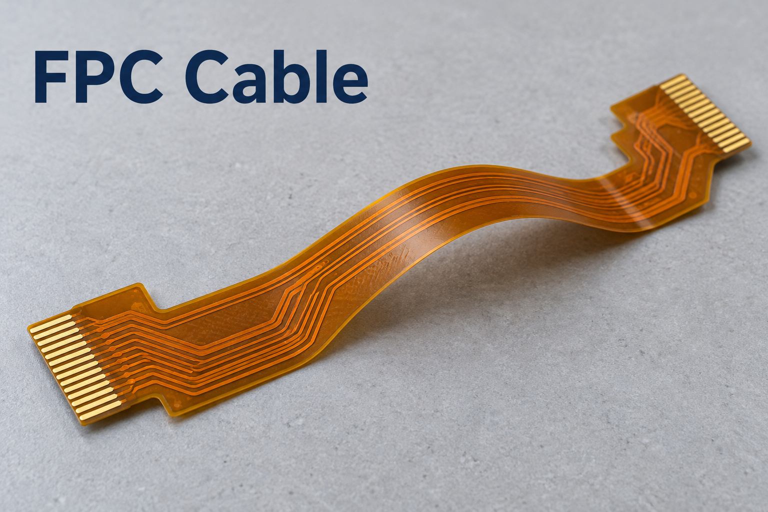
FFC vs FPC Cable: When Does Custom Fabrication Pay Off?
For an FFC vs FPC cable decision, start with the required connections. Use FFC when parallel conductors and available end configurations fit. Choose custom FPC when etched routing, a shaped outline or different terminations can replace extra adapters or simplify assembly.
| Connection requirement | Cable option | Construction |
|---|---|---|
| Straight, matching interfaces | Standard FFC | Parallel laminated conductors |
| Standard contacts, nonstandard length | Custom-length FFC | Parallel conductors; specified length |
| Pin remapping or branches | Custom FPC | Etched circuit paths |
| ZIF and soldered ends | Custom FPC | Separate end geometries |
| Components on the interconnect | Assembled FPC | SMT pads and local support |
Compare total installed cost, including connectors, adapter parts and assembly labor. A custom flex cable is worthwhile when those savings justify circuit engineering and tooling. If standard FFC already fits, custom fabrication may offer little benefit. Pin remapping does not perform active interface conversion.
FPC Cable Connector Fit: Pitch, Contacts and Stiffeners
An FPC cable connector match requires the correct tail thickness, contact side and pin mapping—not just pitch. We translate the mating connector drawings into separate requirements for each end, so the sample is built to the actual interfaces.
Finished tail thickness = local FPC thickness + stiffener + bonding adhesive.
Include only layers present at the insertion zone. Compare the complete thickness tolerance range with the connector’s permitted range; a matching nominal value can still leave parts too thick to latch or too thin for reliable contact.
- Insertion and latching: Match tail width, insertion length and reinforcement boundaries to the connector drawing. Position the stiffener to support insertion without obstructing the housing.
- Contact engagement: Align the exposed contact side, length and position with the contacts and insertion stop. Select the finish for the mating duty; ENIG is not equivalent to wear-resistant hard gold.
- Pin mapping: Specify pin count, numbering and viewing direction at both ends. Resolve conflicting Gerber, connection-diagram and assembly-drawing details before production.
A 0.5 mm FPC cable and a 0.3 mm pitch FPC cable both require these checks. Pitch alone does not establish interchangeability, even when two cables appear identical.
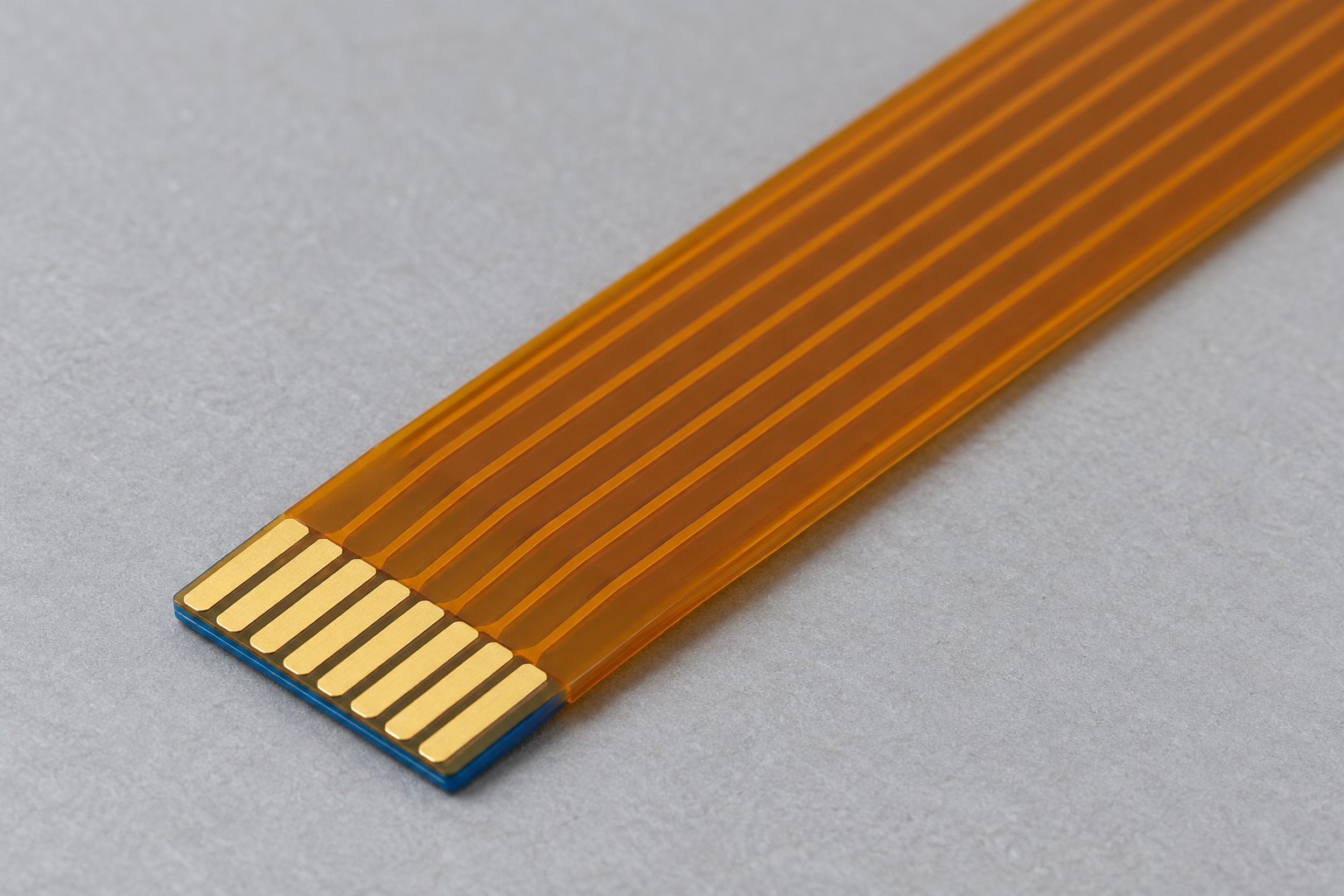
US Customer Case Study: EVK Adapter with ZIF and Soldered Interfaces
This US customer’s two-layer FPC adapter cable combines a ZIF tail with a reinforced solder-pad end. The structure suits evaluation boards and electronic development platforms: the ZIF end permits disconnection, while the soldered end provides a fixed interface. The order specified 15 pieces plus two spares, with panel delivery.
- Two interface thicknesses: Separate PI and FR4 support zones address different insertion and soldering requirements. Our manufacturing plan checks each local finished thickness against its own tolerance, giving sample evaluation clear acceptance dimensions.
- Material and drawing consistency: The customer-approved adhesiveless PI supersedes the older 0.5 mil note. We align the stackup and reinforcement details in production files for customer approval before manufacturing, avoiding conflicting build instructions.
| Parameter | Specification |
|---|---|
| Circuit layers | 2 |
| Copper, L1/L2 | 1/3 oz |
| Base dielectric | 1 mil adhesiveless PI |
| Surface finish | ENIG |
| ZIF reinforcement | 200 µm PI |
| ZIF regional thickness | 0.32 ± 0.03 mm |
| Solder-pad reinforcement | 800 µm FR4 |
| Solder-pad regional thickness | 0.945 ± 0.03 mm |
FPC Cable Bend Radius: Match the Stackup to the Motion
Calculate the preliminary FPC cable bend radius from the finished thickness in the bend and the type of movement. Use the flexible span’s thickness, not a reinforced connector tail elsewhere on the cable.
R = k × t
Here, R is the inside bend radius; t includes copper, dielectric, adhesive, coverlay and shielding in the bend; and k is a screening multiplier for the construction and motion.
| Construction and motion | Initial radius | Layout priority |
|---|---|---|
| Static, 1–2 copper layers | R ≥ 10 × t | Smooth curve; supported terminals |
| Static, 3+ bonded copper layers | R ≥ 20 × t | Space for the bonded stack |
| Repeated dynamic movement | Initially consider R ≥ 100 × t | Thin moving span; fatigue validation |
These rules of thumb support preliminary layout, not guaranteed BestFPC limits. Dynamic life requires validation for the selected materials, temperature, movement and cycle count.
Example: For a hypothetical 0.10 mm bend region, the reference is 1.0 mm for a static 1–2-layer construction or 10 mm for initial dynamic planning. Occasional service movement also needs free length and allowance for repeated access; it is not a one-time installation bend.
Keep pads, vias and stiffener edges outside the curve. For continuous movement, favor consistent conductor widths and, where practical, one copper layer; keep components outside the moving span.
Our stackup DFM compares bend space and current requirements with adhesive or adhesiveless PI and appropriate grades of RA and ED copper. Where space is tight, we assess thinner dielectric or fewer local layers. Our standard pure-flex route lists 1–4 layers and 0.06–0.60 mm finished thickness; the selected combination must suit the application.
Shielded FPC Cable: Balance EMI, Signal Integrity and Flexing
A shielded FPC cable needs a defined grounding arrangement and enough flexibility for its route. For a high speed FPC cable, preserve the reference path beneath critical signals unless an alternative has been evaluated electrically.
| Construction | Electrical role | Mechanical or design constraint |
|---|---|---|
| Solid copper reference/shield | Continuous high-speed return path | Added copper and stiffness |
| Hatched copper | Patterned reference or shield | Less uniform return path; changed impedance |
| EMI shielding film | Thin external shielding | Ground contacts, openings and lamination compatibility |
We assess FPC cable impedance through trace width, spacing, dielectric thickness and reference geometry together. Our controlled-impedance capability is ±10% against an agreed target, stackup and measurement arrangement.
If shielding makes the cable too stiff, assess thinner adjacent layers or a revised route while preserving the required electrical structure. Specific shielding films and application processes are confirmed for each build. Continuity and impedance tests do not establish system EMC compliance; the assembled device still requires evaluation.
FPC Cable Assembly for Compact Electronics
FPC cable assembly for compact electronics must leave room to make the connection, support the components and access the test points. We coordinate fabrication, component sourcing, SMT and agreed testing so a change to the flex does not become a separate negotiation with each supplier.
Connection space. Direct FPC cable soldering can remove a mating connector, but reduces serviceability. For hot bar soldering, reserve tool access, joint support and contact overlap as well as the finished joint footprint.
Component support. We plan stiffeners and carrier support for printing, placement and soldering. Keep the working bend outside the mounting area to avoid concentrating movement at the joint edge.
Assembly and test access. Position probe locations and plan fixtures before enclosure assembly. Perform the agreed checks while joints and test points remain accessible.
For an FPC-to-FFC cable assembly, define both mating interfaces and the pin map first. A transition may need a connector or adapter; the two cable types are not automatically interchangeable.
When comparing a cable assembly with a custom bare FPC, check the delivered scope: circuit only, fitted connectors, or a populated and tested assembly. The same outline does not mean the same quoted work.
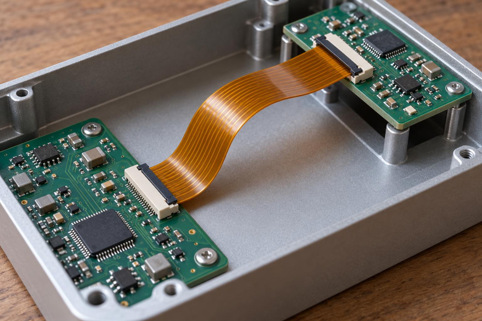
FPC Cable Assembly Quality Checklist
An FPC cable assembly quality checklist should separate electrical acceptance from fit and assembly acceptance. Our FPC boards receive 100% electrical testing before delivery; dimensional and optical checks address defects that an electrical pass cannot detect.
| Inspection item | Method | Acceptance basis |
|---|---|---|
| Tail and outline | Dimensional measurement | Drawing dimensions and regional thickness tolerances |
| Circuit pattern | AOI | Approved artwork; pattern defect criteria |
| Connections and isolation | 100% electrical testing | Approved netlist; opens and shorts |
| Coverlay and stiffeners | Position and condition inspection | Contact openings and reinforcement boundaries |
| Component placement and soldering | First article; applicable SPI/AOI | BOM, orientation and solder-joint criteria |
| Hidden solder joints | X-ray when specified | Agreed joint acceptance criteria |
Measure the insertion zone and reinforced solder area separately. Check reinforcement boundaries against the intended bend area as well as the outline.
Impedance, ICT and functional testing require agreed procedures and suitable access or fixtures. Define bend-life and environmental validation separately before sample approval; these are not included merely because a board passes electrical testing.
How to Choose a Reliable FPC Cable Manufacturer
Choose an FPC cable manufacturer that can connect its quotation to a buildable construction and a workable delivery plan. At BestFPC, the value of our own manufacturing is direct coordination between the people resolving your drawing and those preparing production.
- Fewer supplier handoffs. Our FPC fabrication and PCBA support connect material selection, reinforcement, component assembly and testing. If a change affects several stages, you can address the complete build with one manufacturing partner.
- Experienced decisions across departments. Our engineering, production, quality and business leaders each have over 10 years of relevant experience and long tenure. Material changes, drawing issues and revised quality requirements can be assessed against both production and delivery needs.
- Support for supplier qualification. We serve medical-brand customers and hold relevant ISO 9001, ISO 13485, IATF 16949 and AS9100D certifications. Match the applicable certificate scope and required records to your supplier approval process.
- Purchasing that follows development. No MOQ allows engineering samples and pilot orders at the quantities you need. Approved materials, files and acceptance criteria provide the basis for repeat production, while our teams coordinate material readiness and build milestones.
Use these points as a practical FPC cable assembly supplier guide: ask competing FPC cable suppliers to respond to the same drawing, assembly scope and delivery target. A useful response identifies necessary changes and what the quotation includes, rather than leaving you to resolve the manufacturing assumptions after ordering.
Start a Custom FPC Cable Project with No MOQ
Start your custom FPC cable project with the quantity needed for fit checks or a pilot build. No MOQ avoids committing to production quantities while the design is still changing; free DFM identifies manufacturing questions before the build is released.
Send Gerber and drawings, connector details, quantities and the required US receipt date. Add the BOM and test requirements for assembly.
Confirm layer count, thickness, tail tolerances, finish, shielding and assembly scope so quotations cover equivalent work. Separate unit pricing from applicable tooling, fixture and special-material costs; no MOQ does not eliminate these project costs.
We plan delivery around file approval, material availability, production, inspection and international transit. Providing the receipt date alongside the quantity makes the quotation more useful than requesting an unspecified “fast turnaround.”
Frequently Asked Questions About FPC Cable
Can I request a feasibility review before the Gerber files are complete?
Yes. An outline, connector drawings and the intended installation can support an initial discussion. We identify missing production inputs; manufacturing still requires the final approved file set.
Can our team supply the connectors and other components?
Yes, within an agreed assembly scope. Confirm part numbers, quantities, packaging and arrival dates so shortages or unsuitable packaging can be addressed before the build.
Should I request loose pieces or panels for assembly?
Use your assembler’s handling requirements. Panel rails, locating features, separation method and carrier support can affect cost and usability even when the electrical design stays the same.
What happens if the connector part number changes after quotation?
Send its drawing before order release. Changes to contact geometry, tail thickness or the assembly footprint may require revised production files and pricing.
Can a material substitution be treated as equivalent after sample approval?
Not automatically. Compare thickness, adhesive system, copper and relevant electrical or mechanical properties. Agree on the substitution and any necessary revalidation before using it in a repeat order.
Who owns the tooling and test fixtures paid for with the order?
Specify ownership, storage, reuse and transfer in the quotation or purchase terms. A tooling charge alone does not establish those rights.
Bring your custom FPC cable project to a manufacturer that can coordinate fabrication and assembly. Send drawings, connector details and your US delivery target to sales@bestfpc.com. Our free DFM review identifies fit, stackup and assembly issues for quotation, while no MOQ lets you begin with the quantity needed for validation.


.png)
.png)
.png)
.png)

.png)