


 2026-10-27

 BEST
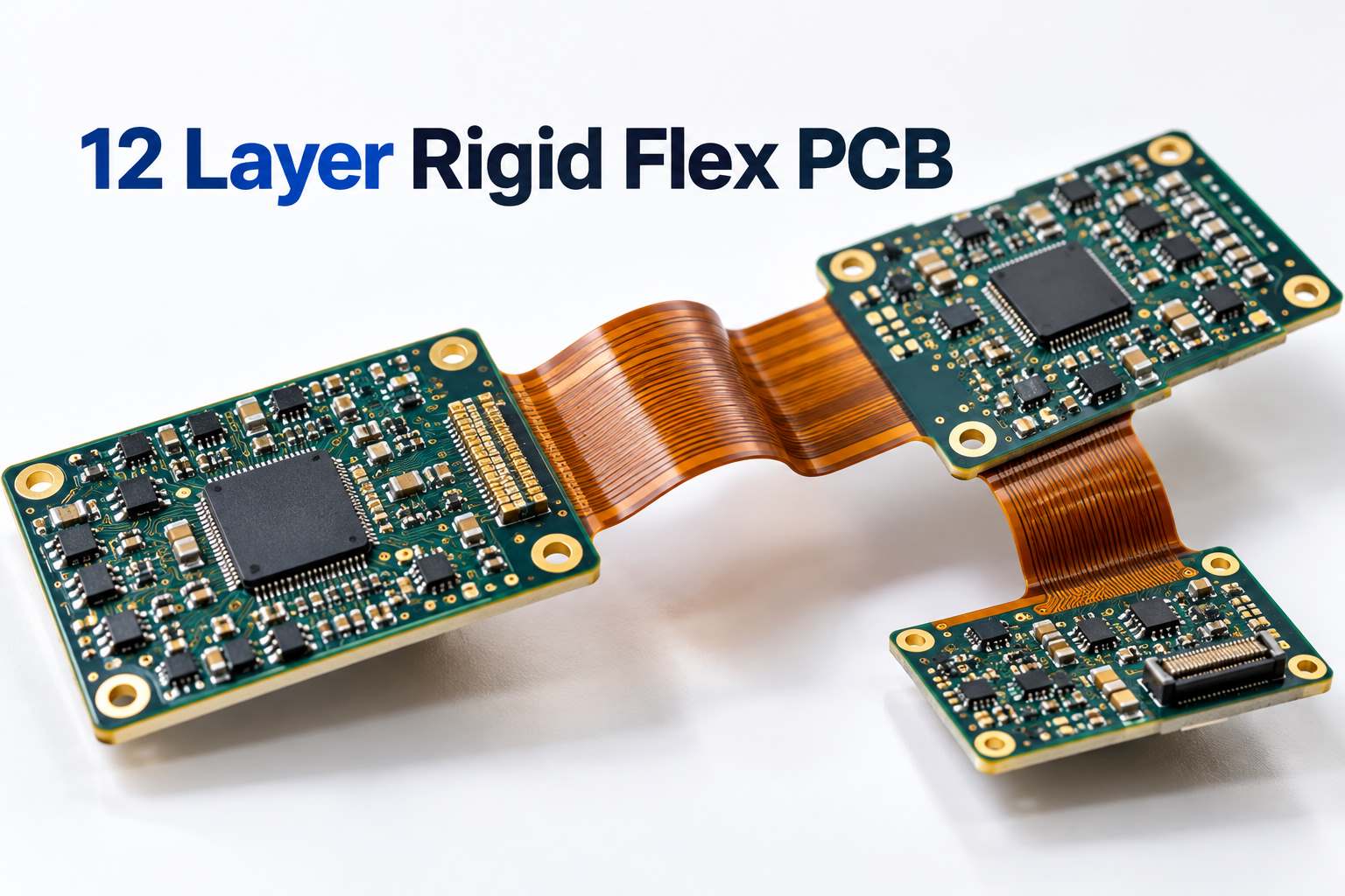
A 12 layer rigid flex PCB combines high-density multilayer circuitry with flexible connections, helping engineers reduce connectors, save assembly space, and fit complex electronics into compact enclosures. The rigid sections accommodate components and dense routing, while flexible sections connect different circuit areas without separate cables.
Complex stackups, fine-pitch routing, and rigid-to-flex transitions require a manufacturer who understands both electrical and mechanical design. At BestFPC, we combine nearly 20 years of PCB manufacturing experience with free DFM support, custom rigid-flex fabrication, and PCB assembly services. Our engineers help identify manufacturing issues early, improve production feasibility, and support your project from prototype to volume production. With no MOQ and ISO 9001 and ISO 13485 quality management systems, you can validate your design with small quantities before scaling production.
Why Choose BestFPC as Your 12 Layer Flex Rigid PCB Manufacturer?
Choosing a reliable 12 layer flex rigid PCB manufacturer means finding a supplier capable of handling dense multilayer routing, material compatibility, and flexible interconnections within one design. These details affect production yield, mechanical reliability, and overall manufacturing cost.
BestFPC supports customers with engineering expertise, flexible ordering, and coordinated manufacturing services.
-
Nearly 20 years of PCB manufacturing experience: Our experienced engineering and production teams support complex multilayer and rigid-flex projects, helping customers address technical requirements before manufacturing.
-
Free DFM review: Identify potential issues with stackup construction, via placement, trace spacing, and rigid-to-flex transitions before production.
-
No MOQ: Order prototypes and small batches without committing to unnecessary inventory, then increase quantities as demand grows.
-
PCB fabrication and assembly: Work with one supplier for custom PCB manufacturing, component sourcing, SMT assembly, and inspection.
-
Established quality systems: ISO 9001, ISO 13485, IATF 16949, and AS9100D quality management certifications support customers with different supplier qualification requirements.
Our advantage extends beyond manufacturing the bare PCB. When engineering changes occur, customers can coordinate stackup adjustments, fabrication requirements, and assembly considerations through the same manufacturing partner. This helps reduce unnecessary communication between separate suppliers and keeps project requirements consistent.
What Is a 12 Layer Rigid-Flex PCB?
A 12 layer rigid-flex PCB combines rigid circuit sections and flexible interconnections within a single multilayer structure. The rigid regions provide mechanical support for components and dense routing, while the flexible portions connect separate circuit areas and allow the assembly to fit into three-dimensional spaces.
A twelve-layer rigid-flex design does not necessarily contain twelve copper layers throughout the entire board. For example, the rigid sections may contain twelve conductive layers while only two or four layers continue through the flexible connection.
This arrangement allows engineers to use additional routing layers where components are concentrated while maintaining a thinner, more flexible structure between rigid sections.
Compared with using separate rigid PCBs connected by cables, rigid-flex construction offers several practical advantages:
-
Compact assembly: Flexible interconnections allow circuit sections to occupy different positions inside the enclosure.
-
Fewer connectors: Integrated copper connections can replace selected board-to-board connectors and ribbon cables.
-
Reduced assembly work: Fewer individual interconnections can simplify product assembly.
-
Flexible mechanical design: Rigid sections can be positioned around the product's mechanical structure.
The most suitable construction depends on component density, signal requirements, available space, and the expected bending conditions.
How Is a 12 Layer PCB Stackup Designed for Rigid-Flex Applications?
A 12 layer PCB stackup for rigid-flex applications must accommodate dense electrical routing while preserving the required mechanical flexibility.
A common design approach is to place twelve copper layers in the rigid regions and use fewer continuous layers through the flexible sections. The exact arrangement depends on the number of signals crossing between rigid areas, controlled-impedance requirements, and the available space.
Layer Distribution
Signal, ground, and power layers should be arranged to support routing density and electrical performance. High-speed signals may require adjacent reference planes, while power distribution must provide sufficient current capacity.
Flexible Layer Count
Two-layer flex sections can be suitable when routing requirements are moderate. More flexible layers may be needed for additional signal connections, but they also increase thickness and influence bending performance.
Keeping the flexible construction as simple as the electrical design allows can improve mechanical flexibility and reduce fabrication complexity.
Material Selection
Rigid-flex designs commonly combine rigid laminate materials with polyimide flexible cores, copper foil, and coverlay.
Material selection affects dielectric thickness, dimensional stability, electrical performance, and bending behavior. Copper type and thickness are especially important in flexible regions.
Controlled Impedance and HDI
High-density devices may require controlled-impedance routing, blind vias, buried vias, or laser microvias.
When high-speed signals transition between rigid and flexible regions, differences in dielectric construction and reference-plane geometry must be considered.
BestFPC's engineering team can review your proposed stackup, identify potential fabrication conflicts, and recommend practical adjustments before production.

What Are BestFPC's 12 Layer Rigid Flex PCB Manufacturing Capabilities?
Manufacturing a twelve-layer rigid-flex board involves accurate conductor formation, multilayer registration, drilling, plating, and lamination. Fine-pitch layouts and HDI structures require particularly careful control of these processes.
BestFPC supports multilayer FPC manufacturing with fine-line routing and HDI processing capabilities. The following values are drawn from our multilayer FPC HDI design guidelines for applicable constructions using 1/3 oz or 1/2 oz base copper.
| Manufacturing Parameter | Standard Design | Advanced Design |
|---|---|---|
| Inner trace/space, non-plated core | 0.075/0.075 mm | 0.060/0.060 mm |
| Inner trace/space, HDI buildup | 0.100/0.100 mm | 0.080/0.080 mm |
| Outer trace/space | 0.125/0.125 mm | 0.100/0.100 mm |
| Laser microvia diameter | 0.075–0.100 mm | 0.060 mm |
| Mechanical through-hole drill | 0.15 mm | Project-specific review |
BestFPC combines fine-line manufacturing, HDI processing, and multilayer fabrication experience to support demanding rigid-flex PCB designs. Our engineering team helps optimize trace spacing, via structures, copper thickness, and stackup construction for reliable production.
For twelve-layer projects, we also review rigid and flex thickness, material compatibility, via configurations, bending requirements, and controlled impedance. This allows us to develop a manufacturing approach around the actual board construction rather than relying on layer count alone.
If your design includes multiple rigid islands, dense BGA routing, or specialized HDI structures, send your fabrication files to sales@bestpcbs.com for a free DFM review and manufacturing evaluation.
What Are the Key Challenges in Rigid Flex PCB Design?
A complex rigid flex PCB design must satisfy electrical and mechanical requirements simultaneously. Four areas deserve particular attention during the engineering and manufacturing stages.
1. Layer Registration and Lamination
Twelve-layer structures require accurate alignment between copper layers during lamination. Registration errors may affect drilled-hole alignment and conductor clearance.
BestFPC reviews the layer construction, drill-to-pad relationships, and manufacturing allowances to help improve fabrication consistency.
2. Rigid-to-Flex Transitions
The junction between rigid and flexible sections experiences concentrated mechanical stress during bending and installation.
Placing vias, pads, or unsuitable copper features near these transitions can increase the risk of mechanical damage. Appropriate keep-out areas, conductor routing, and transition geometry help improve reliability.
3. Bend Radius and Copper Fatigue
Flexible sections must accommodate the required bending angle without exceeding suitable material strain limits.
Bend radius depends on flex thickness, copper construction, and whether the board bends once during installation or repeatedly during operation.
For dynamic applications, the flexible section requires careful material selection and bending validation. A thinner flex construction with fewer copper layers may be preferable when the design allows it.
4. HDI Routing and Signal Integrity
Dense component layouts may require microvias and fine-pitch routing. These features introduce additional manufacturing requirements for drilling, plating, and lamination.
Controlled-impedance signals also require attention when transitioning between rigid and flexible regions because the surrounding dielectric structure may change.
BestFPC's free DFM review helps identify these issues before fabrication, giving engineers an opportunity to adjust the design while changes are still practical.
Where Are 12 Layer Rigid Flex PCBs Used?
Twelve-layer rigid-flex boards are particularly useful in products requiring dense electronic circuitry and compact mechanical packaging.
Aerospace and Avionics
Communication modules, navigation electronics, and control systems may require multiple circuit sections arranged within restricted equipment spaces. Rigid-flex construction can reduce separate cabling while supporting multilayer signal routing.
Medical Imaging and Diagnostic Equipment
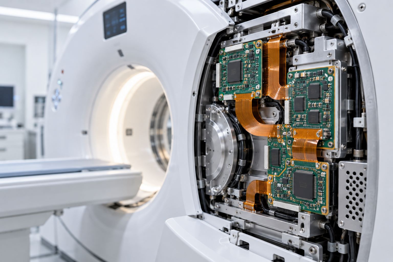
Medical imaging systems and advanced diagnostic instruments may use rigid-flex boards to connect sensors, processing circuits, and interface modules. Compact construction and controlled manufacturing requirements make rigid-flex technology suitable for demanding medical electronics.
Industrial Automation and Robotics
Industrial control systems and robotic equipment often contain several electronic modules positioned around motors, sensors, and mechanical structures. Rigid-flex interconnections help engineers arrange these modules within complex enclosures.
Applications involving repeated mechanical movement require additional evaluation of the flexible section.
High-Speed Imaging and Data Acquisition
High-resolution cameras, measurement instruments, and data-acquisition equipment may need dense multilayer routing, controlled impedance, and flexible connections between processing and sensor sections.
For these applications, rigid-flex construction can help reduce separate interconnections while accommodating demanding circuit layouts.
How Does BestFPC Ensure Quality in Rigid-Flex PCB Manufacturing?
Reliable twelve-layer rigid-flex production requires consistent control of materials, lamination, conductor geometry, and electrical interconnections.
BestFPC incorporates engineering review, manufacturing inspections, and electrical testing into the production process to support consistent board quality.
Our quality-control approach includes:
-
DFM verification: Review stackup, materials, drilling requirements, bend regions, and manufacturing tolerances before production.
-
Inner-layer inspection: Check conductor patterns and identify potential circuit defects before lamination.
-
Lamination and drilling control: Monitor layer registration and critical interconnection features during fabrication.
-
Electrical testing: Verify circuit continuity and isolation against the approved electrical test data.
-
Final inspection: Evaluate dimensions, workmanship, and applicable product acceptance requirements.
For medical, aerospace, and other high-reliability projects, customers may also require additional inspection records, material documentation, or traceability.
BestFPC's ISO 9001 and ISO 13485 quality systems, together with applicable industry-specific quality management certifications, can support supplier qualification and documented manufacturing requirements.
For customers changing PCB suppliers, consistent manufacturing documentation and engineering communication are especially valuable. Our team can review the existing design requirements and help establish a clear production specification before repeat manufacturing.
Can BestFPC Provide 12 Layer Rigid Flex PCB Assembly?
Yes. BestFPC provides 12 layer rigid flex PCB assembly services, combining PCB fabrication, component sourcing, SMT assembly, inspection, and testing under one manufacturing partner. For complex rigid-flex boards, our engineering team also evaluates component placement, assembly fixtures, and flexible-section protection to support stable processing and reliable solder connections.
BestFPC's SMT assembly capabilities support fine-pitch components, dense circuit layouts, and both prototype and volume production. Our assembly equipment and production capacity include:
| SMT Assembly Capability | BestFPC Specifications |
|---|---|
| Component Placement Capacity | 13,200,000 chips/day |
| Supported PCB Size | 0.2 × 0.2 to 20 × 20 inches; up to 22 × 47.5 inches for applicable equipment |
| Minimum SMD Component | 01005 |
| Minimum BGA Pitch | 0.25 mm |
| Assembly Types | SMT, THT, mixed assembly |
| Component Packaging | Reels, cut tape, tubes, trays, loose parts |
| Assembly Lead Time | 1–5 days for eligible orders, subject to project requirements |
For 12-layer rigid-flex assemblies, stable component placement and proper support of flexible sections are particularly important. BestFPC reviews board geometry, component distribution, and fixture requirements before assembly. AOI, X-ray inspection, and project-defined functional testing can be incorporated according to the component types and quality requirements.
One supplier for PCB fabrication and assembly means fewer manufacturing handoffs and easier engineering coordination. Whether your project requires fine-pitch BGA assembly, a small prototype batch, or repeat production, BestFPC can help coordinate the manufacturing process.
Send your Gerber files, BOM, assembly drawings, and quantities to sales@bestpcbs.com for a combined PCB fabrication and assembly quotation.
How Much Does a Custom 12 Layer Rigid Flex PCB Cost?
The cost of a custom twelve-layer rigid-flex PCB depends on the manufacturing complexity rather than layer count alone.
Board dimensions, rigid and flex layer distribution, copper thickness, HDI structures, material selection, and order quantity all influence the final price.
A board with two rigid sections connected by a simple flex region may require fewer manufacturing operations than a design containing multiple rigid islands, blind vias, and complex routing transitions.
Several design choices can help control cost:
-
Optimize the flex-layer count: Use two flexible copper layers where routing requirements allow, rather than adding layers without a clear electrical need.
-
Review via structures: Select blind vias, buried vias, or microvias where they provide a meaningful routing advantage.
-
Improve material utilization: Consider board outlines, flexible connection lengths, and panel arrangements during manufacturing review.
-
Validate prototypes first: Confirm electrical performance and mechanical fit before increasing production quantities.
BestFPC's free DFM review can help identify practical design adjustments that improve manufacturability and avoid unnecessary fabrication complexity.
With no MOQ, customers can start with prototype quantities and request pricing for larger production volumes when the design is ready.
Get a Custom Flex Rigid PCB Manufacturing Quote from BestFPC
Your 12-layer rigid-flex PCB deserves a manufacturer who can handle complex stackups, fine-pitch routing, and challenging rigid-to-flex transitions. With nearly 20 years of PCB manufacturing experience, BestFPC provides free DFM support, custom fabrication, and coordinated PCB assembly to help you reduce unnecessary design revisions and move confidently from prototype to production.
Get expert manufacturing support before committing to production. Whether you need 10 prototype boards or a larger production run, our engineering team can review your design, identify cost-saving opportunities, and recommend practical manufacturing solutions.
Send your Gerber files, stackup, quantities, and target delivery date to sales@bestpcbs.com for a custom quotation and DFM review. If your project includes PCB assembly, you can also submit the BOM and assembly drawings for coordinated PCBA pricing.
FAQs about 12 Layer Rigid Flex PCB
1. How thick is a 12 layer rigid flex PCB?
The thickness depends on the copper weight, dielectric materials, and layer configuration. The rigid sections are generally thicker than the flexible connections. A finished thickness should be established through the approved stackup.
2. How many flexible layers can a 12 layer rigid flex PCB have?
A twelve-layer rigid-flex board may use two, four, or another suitable number of copper layers in the flexible sections. The choice depends on electrical routing and mechanical bending requirements.
3. What is the minimum bend radius for a 12 layer rigid flex PCB?
The minimum bend radius depends on flexible-section thickness, copper construction, and bending frequency. It should be calculated for the actual flex stackup rather than the twelve-layer rigid section.
4. Can a 12 layer rigid flex PCB use blind and buried vias?
Yes. Blind and buried vias can support high-density routing in suitable twelve-layer rigid-flex constructions. The exact via structure must be reviewed against the manufacturing stackup.
5. How long does it take to manufacture a 12 layer rigid flex PCB?
Lead time depends on stackup complexity, material availability, HDI processing, order quantity, and testing requirements. BestFPC confirms project-specific manufacturing schedules after reviewing the design files.
6. What files are required for a 12 layer rigid flex PCB quotation?
Provide Gerber or ODB++ files, the proposed stackup, fabrication drawings, order quantities, and target delivery date. For assembly quotation, include the BOM, pick-and-place data, and assembly drawings.
With nearly 20 years of PCB manufacturing experience, BestFPC offers free DFM support, no MOQ, and one-stop rigid-flex PCB fabrication and assembly, backed by ISO 9001, ISO 13485, IATF 16949, and AS9100D certifications. Whether you need prototypes or volume production, our experienced engineering team can help optimize your design for reliable manufacturing and cost efficiency. Send your Gerber files, stackup, and quantities to sales@bestpcbs.com for a free DFM review and a competitive 12 layer rigid flex PCB quotation.


.png)
.png)
.png)
.png)

.png)