


 2026-10-16
 BEST
BESTHot bar soldering can connect an FPC directly to a rigid PCB without a separate mating connector. A reliable connection starts with a flex termination that lets heat reach the solder, keeps the contacts aligned, and accommodates the intended assembly process. Choosing the right FPC means considering its exposed copper, insulation, thickness, and support together.
BestFPC manufactures FPCs for hot bar soldering applications and provides DFM review of existing customer designs. With experienced PCB/PCBA engineers and prototype and small-batch support, we help you assess fabrication details before ordering. Send your existing Gerber files, stackup, and connection requirements to sales@bestfpc.com for a manufacturability review and quotation.
What Is Hot Bar Soldering?
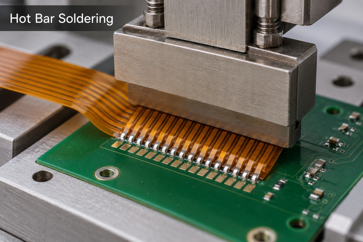
Hot bar soldering uses a heated tool, called a thermode, to reflow solder at a localized connection while holding the parts together. For FPC-to-PCB connections, aligned flex conductors overlap corresponding pads on the rigid board.
In a pulse-heated process, the basic sequence is:
- Align and support: A fixture locates the parts and supports the joining area.
- Apply heat and force: The thermode transfers heat into the connection until the prepared solder reflows.
- Cool before release: Force is maintained as the solder solidifies, helping the parts stay in position.
The resulting connection is a soldered joint. Although similar equipment can also be used for adhesive bonding, hot bar soldering and ACF bonding use different joining materials and mechanisms.
When Is Hot Bar Soldering Suitable for FPC-to-PCB Connections?
Consider hot bar soldering when a compact, permanent flex-to-board connection suits the product. The assembly must also provide access for the thermode and support beneath the joint.
It is particularly relevant when:
- Connector space is limited: Direct attachment can remove the mating connector from the interface, although the soldering tool still needs assembly clearance.
- A row of contacts needs joining: A suitable thermode can heat multiple aligned contacts in one operation.
- Routine disconnection is unnecessary: A soldered interface can suit an assembly that remains connected throughout normal use.
A detachable connector may be more practical when the flex must be unplugged for service or assembled in separate stages. Hot bar soldering also becomes less attractive if surrounding components obstruct the tool or the joining area cannot be supported adequately.
Which FPC Termination Structure Should You Choose?
Choose the termination around heat access, handling strength, and the space available for solder to flow. Three common constructions give the assembler different ways to reach the conductors.
| Termination | Main advantage | Main constraint |
|---|---|---|
| Exposed lead | Direct heat access | Delicate unsupported leads |
| Single-sided | Insulated upper surface | Heat passes through insulation |
| Open-windowed | Exposed joining area | Thermode must fit window |
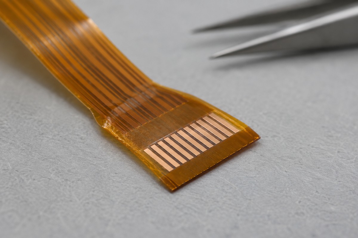
- Exposed lead: Insulation is removed from both sides of the joining section. The thermode can contact the conductors directly, but the unsupported copper needs careful handling.
- Single-sided: Copper is exposed on the mating side while insulation remains above it. The insulation becomes part of the heat-transfer path, and the construction leaves less space for excess solder to escape.
- Open-windowed: An opening exposes the joining region while surrounding material provides support. Window dimensions must accommodate the thermode and the intended contact area.
Here, “single-sided” describes access at the termination; it should not be used by itself to specify the complete FPC layer count. Show the required openings and exposed copper clearly in the fabrication drawings.
How Do FPC Materials and Thickness Affect Hot Bar Reflow Soldering?
The material between the thermode and the solder affects how quickly heat reaches the joint. Total FPC thickness alone does not describe that path.
For hot bar reflow soldering, review three construction details:
- Insulation over the joint: In a single-sided termination, heat passes through the insulating layer. Its thickness and material therefore matter at the actual joining area.
- Copper distribution: Nearby copper can carry heat away from the connection. Uneven copper distribution can make uniform heating across the contact row more difficult.
- Coverlay, adhesive, and reinforcement: Their positions affect local thickness, tool contact, and support. Keep the joining-area construction explicit rather than relying only on a general stackup drawing.
The thermode temperature reading is not the same as the temperature inside the solder joint. The assembler needs to establish the heating and cooling profile for the selected materials, solder alloy, tooling, and joint geometry. A higher setpoint cannot reliably correct poor contact or an unsuitable heat path.
How Do Pad Geometry and Solder Volume Affect Joint Quality?
Pad geometry and solder quantity must work together to produce separate, consistently wetted connections. More solder does not automatically make a stronger joint.
The most useful hot bar soldering design rules connect the FPC termination to the mating PCB and assembly tooling:
- Match the contact pattern: Check conductor pitch, pad overlap, and alignment allowance across both parts. Each flex conductor must reach its intended PCB pad without approaching its neighbor too closely.
- Control the deposited solder: The required amount depends on pad dimensions, pitch, and termination construction. Excess solder has less escape space beneath an insulated termination than around exposed leads.
- Allow tool access: Openings and nearby features must let the thermode contact the intended joining region without interference.
- Provide a stable reference: Locating features and support beneath the joint help the assembler maintain alignment and even contact.
Review both sides of the connection before releasing the FPC for fabrication. A correctly manufactured flex can still be difficult to join if the mating PCB footprint, solder deposit, or fixture does not suit it.
What Causes Bridging and Weak Hot Bar Solder Joints?
Bridging and weak joints can result from different problems, so the defect should guide the investigation. Increasing heat or force without identifying the cause can introduce further damage.
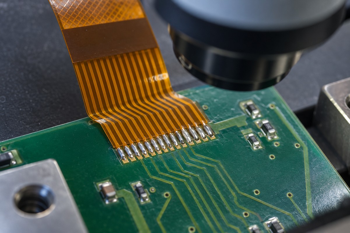
- Solder bridges: Check excess solder, contact alignment, and the space between adjacent conductors. Inspect whether solder has been displaced toward neighboring pads.
- Incomplete wetting or open connections: Check surface condition, flux compatibility, and whether enough heat reached every joint. Uneven thermode contact can leave part of the row insufficiently heated.
- Damaged copper or insulation: Examine thermal exposure, tool contact, support, and handling. Burning, lifted pads, or separated layers require investigation before further assembly.
- Failure after installation: Check whether bending or pulling loads reach the soldered interface. The flexible span should accommodate movement without making the solder joint the hinge point.
Evaluate hot bar solder joints through visual inspection and electrical testing, with mechanical or application-specific tests where required. Continuity confirms an electrical path at the time of testing; it does not by itself establish resistance to repeated bending or service loads.
Why Choose BestFPC for FPCs Used in Hot Bar Soldering?
BestFPC supports customers who already have a design and need FPC fabrication with manufacturability feedback. Our focus is on producing the flex circuit to the approved requirements and identifying fabrication concerns before the build.
For hot bar soldering applications, that support includes:
- Review of existing fabrication files: Assess the specified stackup, copper features, coverlay openings, and termination details for FPC manufacturability.
- Feedback on critical interfaces: Review the documented joining area and reinforcement boundaries so fabrication details can be discussed with your engineering and assembly teams.
- Prototype and small-batch supply: Provide FPC samples for fit checks and soldering trials before a larger production order.
DFM feedback helps refine an existing design for manufacturing. Your assembly team establishes and validates the hot bar soldering process using the actual FPC, mating PCB, solder, and tooling.
FAQs about hot bar soldering
Can every FPC be used for hot bar soldering?
No. The termination must provide a suitable heat path, exposed contact geometry, and access for the tooling. An FPC intended for a plug-in connector should not automatically be treated as suitable for direct soldering.
Is a hot bar soldered connection detachable?
It is a permanent connection during normal use. Removal requires a controlled rework process and may damage the flex or mating pads. Choose a connector when routine disconnection is required.
Can a thicker stiffener improve the soldered connection?
Not automatically. A stiffener can support a termination, but its thickness and position also affect the assembly geometry. Review its placement relative to the tool, joint, and bend region.
Do you need completed design files to request FPC manufacturing?
Existing Gerber files, a stackup, and fabrication drawings provide the basis for a manufacturing review. Include the termination details and mating-interface requirements so BestFPC can assess the proposed FPC construction.
Does FPC DFM review replace hot bar soldering trials?
No. DFM review addresses manufacturability of the supplied design. Soldering trials verify how the fabricated FPC performs with the assembler's materials, tooling, and process settings.
Ready to manufacture FPCs for your hot bar soldering application? Email your existing Gerber files, stackup, termination drawings, and required quantity to sales@bestfpc.com. BestFPC can review the fabrication requirements and quote prototypes or production quantities for your approved design.


.png)
.png)
.png)
.png)

.png)