


 2026-10-16
 BEST
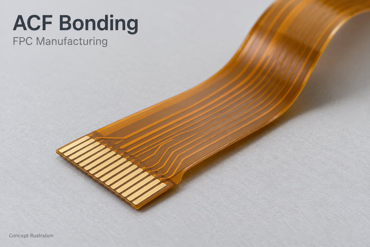
BESTACF bonding creates a thin electrical connection between an FPC and a mating circuit board or glass substrate. A reliable interface starts with matching the FPC pads, surface finish and construction to the conductive film and the customer's bonding process.
The key design question is whether every contact can remain aligned and properly supported while heat and pressure are applied. Resolving this before fabrication helps avoid an FPC that passes bare-board inspection but proves difficult to connect consistently.
Developing an FPC for an ACF connection? Send your preliminary drawing and mating-pad layout to sales@bestfpc.com. BestFPC can review the FPC manufacturing requirements before you finalize the design.
What Is ACF Bonding?
ACF bonding uses anisotropic conductive film, an adhesive containing conductive particles, to join opposing electrodes. Heat and pressure bring particles into contact with the facing pads, while the resin provides adhesion and insulation between neighboring contacts.
A reliable ACF bond therefore needs both electrical contact and mechanical attachment. Conductivity alone does not establish the strength or durability of the joint.
For FPC applications, two common arrangements are:
- FPC to board: The flex terminals connect to matching pads on a circuit board.
- FPC to glass: The flex terminals connect to electrodes on a glass substrate, such as a display interface.
These interfaces need different material and process evaluations. Neither directional conduction nor a small pad pitch guarantees a successful connection.
When Is ACF Bonding Suitable for FPC Connections?
Consider ACF when connection thickness and closely spaced contacts matter, particularly where a conventional connector is difficult to accommodate. The mating surface and future disconnection needs also influence the choice.
| Connection method | Useful when | Main consideration |
|---|---|---|
| ACF bonding | Thin, closely spaced interfaces | Film and process compatibility |
| Soldering | Solderable pads are available | Heat exposure and solder control |
| Connector | Repeated disconnection is needed | Height and mating space |
An FPC-to-glass interface should not inherit the joining assumptions of a solderable PCB interface. Choose around the actual electrodes, assembly space and service requirements.
How Does ACF Conductive Film Selection Affect FPC Pad Design?
ACF conductive film selection affects the contact area, spacing and thermal conditions that the FPC must accommodate. Select the film and terminal geometry together, before either specification is frozen.
Match the film to three aspects of the interface:
- Mating materials: Identify whether the FPC connects to PCB pads, glass electrodes or another flex circuit. A film qualified for one interface should not be assumed suitable for another.
- Particle system: Compare the supplier's minimum connection-area and spacing requirements with the proposed pads. Smaller pads leave less area for capturing conductive particles; increasing particle density is not automatically a solution because neighboring-contact insulation also matters.
- Adhesive system: Check whether the required bonding conditions suit the substrates and nearby materials. The resin system also affects environmental performance and rework options.
Treat the ACF film grade as part of the interface specification. If the film changes, reassess its compatibility with the existing FPC rather than treating all conductive films as interchangeable.
How Does the ACF Bonding Process Affect FPC Design?
The ACF bonding process requires an accessible contact area, repeatable alignment and stable support. A typical sequence is film prelamination, alignment and final thermocompression bonding.
- Prelaminate the film: Position the specified ACF bonding tape or film over the intended area. Keep the contact region free of features that obstruct placement.
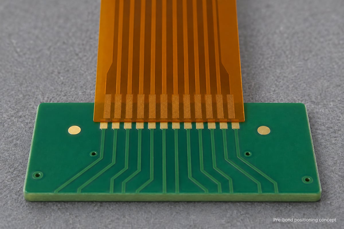
- Align the parts: Register the opposing pads using visible reference features. Allow the tooling to hold the thin FPC without distorting its terminal array.
- Complete the bond: Apply the material-specific thermal and pressure cycle, including the prescribed cooling and release conditions.
The selected ACF bonding machine determines practical access and positioning constraints. Discuss these with the bonding partner while the FPC layout can still be adjusted.
How Does the ACF Bonding Head Affect FPC Layout?
The ACF bonding head must reach the joint and apply controlled loading through a suitably supported area. Its heated contact tool, often called a thermode, needs to work with the local FPC geometry.
Resolve these layout details before fabrication:
- Contact footprint: Keep nearby components and unintended thickness steps clear of the tool's working area.
- Flat support: Review the backing fixture and the contact region together. A local coverlay or reinforcement step can change how the tool loads the joint.
- Stiffener transitions: Use reinforcement where the assembly needs it, but position its edge deliberately relative to the bonding area and the flex exit.
- Flex exit: Leave room for the tail to route away without immediately pulling or peeling at the connection.
An ACF bonder's force setting is not itself a pressure specification. Average pressure depends on force divided by the relevant loaded area; the material supplier's area convention must be understood. Agree on the ACF bonding pressure and how it will be verified with the bonding partner, rather than copying a machine setting from another design.
How Should FPC Pads Be Designed for ACF Bonding?
Define the pads by their effective overlap and separation under manufacturing and assembly tolerances. Nominal pitch alone cannot establish whether the interface will connect reliably.
- Pad width and spacing: Include etching tolerance and the expected alignment error when checking contact separation.
- Overlap at tolerance limits: Compare both pad drawings at their permitted positional extremes. A centered drawing can hide insufficient contact area at the ends of the tolerance range.
- Coverlay opening: Expose the intended contact surface and specify the allowable opening position. Account for possible adhesive encroachment at its boundary.
- Alignment references: Dimension the array to the features used by the assembly system. The cut outline may serve a different purpose from the optical alignment marks.
Evaluate the whole array, not just its center. A small mismatch repeated across many contacts can leave the outer pads with less overlap than expected.
Which FPC Surface Finish Suits ACF Bonding?
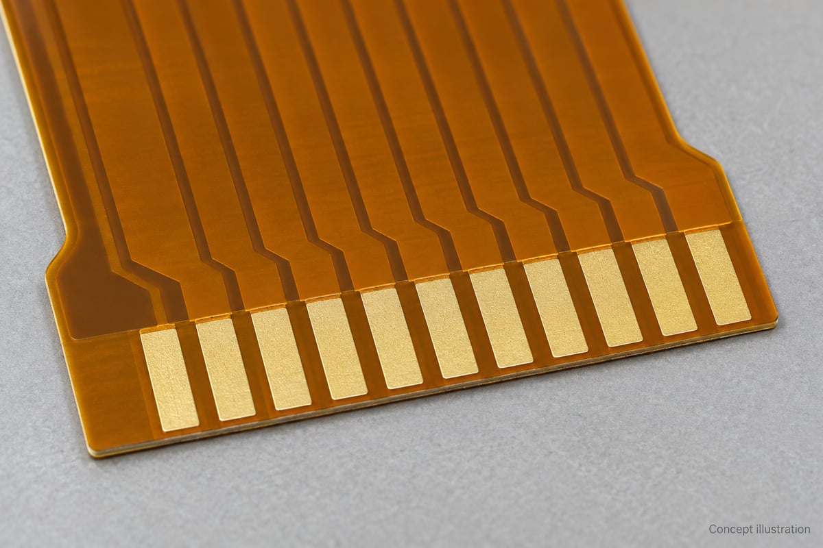
Use a finish that provides a clean, consistent contact surface and is compatible with the selected film and mating electrode. Specify the finish and its relevant tolerances instead of relying on the appearance of a gold-colored pad.
- Surface condition: Control contamination, handling damage and residues in the contact area.
- Finish consistency: Define the required coating system and thickness limits so the supplied contact surface is repeatable.
- Interface validation: Evaluate representative finished FPCs with the intended film and bonding conditions before adopting the combination for production.
A finish selected for solderability is not automatically validated for ACF. Cleaning and surface preparation also need to suit the adhesive and the finished FPC.
How Does ACF Bonding Temperature Affect FPC Materials and Alignment?
ACF bonding temperature must meet the selected film's bonding requirements while staying compatible with the complete FPC and mating assembly. The machine's thermode setting and the temperature reached at the joint are not necessarily identical.
Review three effects together:
- Heat transfer: Establish the required temperature at the interface using a suitable measurement method. Tooling, material thickness and the mating board can influence heat flow.
- Material compatibility: Consider the base film, coverlay adhesive, stiffener adhesive and nearby components. A heat-resistant base film alone does not qualify the entire assembly.
- Dimensional change: Check pad alignment under the actual process conditions. Any artwork compensation should follow measurements on the intended construction, not an assumed expansion factor.
Review heat-related construction risks, including flex PCB delamination, as part of this evaluation.
If the assembly cannot tolerate a proposed cycle, investigate a compatible film and process combination. Simply lowering the temperature can leave the adhesive insufficiently bonded; increasing time is not automatically an equivalent substitute.
How Should FPC Quality Be Verified Before Bonding?
Verify the FPC against the released drawing before evaluating the completed connection. Bare-board acceptance and bonded-joint qualification answer different questions.
For the manufactured FPC, check:
- Electrical integrity: Continuity and isolation against the circuit design.
- Terminal geometry: Pad dimensions, coverlay opening and position relative to alignment references.
- Surface quality: Finish condition, cleanliness and visible damage.
- Construction: Relevant thicknesses and reinforcement positions.
After bonding, the customer or bonding partner should evaluate contact resistance, adjacent-contact isolation and mechanical strength using agreed methods. Environmental and flex testing should reflect the intended application.
A low initial resistance does not establish long-term reliability, and a strong adhesive attachment does not prove that every electrical contact is sound. Assess both.
Why Choose BestFPC for Your FPC Manufacturing?
BestFPC manufactures FPCs for designs that use ACF connections, with engineering review focused on the flex circuit's construction and manufacturability.
Our support connects drawing details to the supplied FPC:
- Manufacturability review: Discuss stackup, terminal geometry, coverlay openings and dimensional requirements before releasing the design.
- Support and routing review: Evaluate stiffener placement and bend regions so the FPC fits the intended assembly arrangement.
- Defined inspection requirements: Agree on the electrical, dimensional and surface checks relevant to your order.
Provide the mating-pad drawing alongside the FPC files. Requirements from your film supplier and bonding partner help BestFPC review the board in the context of its actual connection.
FAQs about ACF bonding
What is the minimum pad pitch for an ACF connection?
There is no universal minimum. Feasibility depends on pad geometry, the selected film, FPC tolerances and the available ACF bonding equipment. Validate the complete interface rather than adopting a generic pitch claim.
Can an existing soldered FPC design be converted to ACF bonding?
Possibly, but review the terminal geometry, finish, coverlay opening and support arrangement. A soldered joint's design rules do not automatically satisfy an adhesive connection's requirements.
Does every bonding area need a stiffener?
No. A temporary fixture may provide the necessary process support. A permanent stiffener should be included where handling or the final assembly requires it, with its thickness and position considered in the tooling design.
Can an ACF-bonded FPC be reworked?
Some material systems permit rework, but removal and cleaning can damage or deform the FPC. Follow the film supplier's procedure and qualify the repaired interface; do not assume the removed flex can be reused.
Does BestFPC provide the complete ACF bonding operation?
Our primary offering for these projects is FPC manufacturing. Film selection, bonding and finished-joint qualification should be coordinated with the customer or their bonding partner.
Ready to manufacture an FPC for an ACF connection? Send your Gerber files, FPC drawing, mating-pad layout and expected quantity to sales@bestfpc.com. BestFPC can review the manufacturing requirements and discuss prototype or production options for your design.


.png)
.png)
.png)
.png)

.png)