


 2026-10-26

 BEST
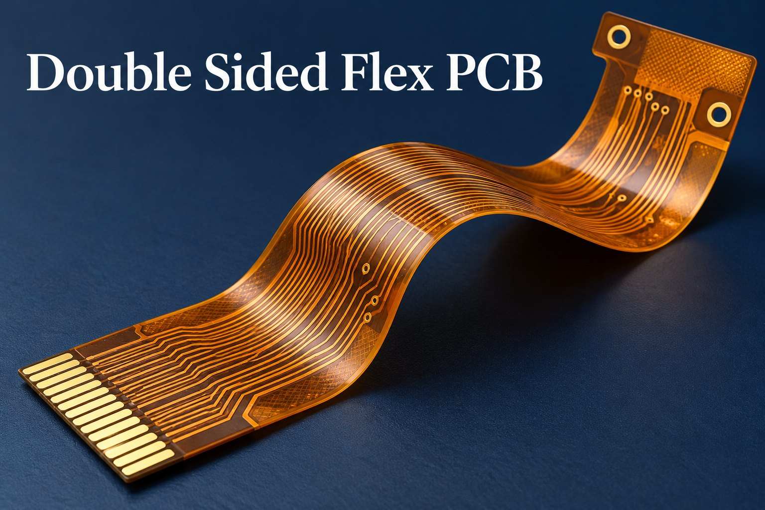
For US buyers sourcing a double sided flex PCB manufacturer, BestFPC provides custom two-layer flexible circuits with engineering review and optional SMT assembly. BestFPC is a China-based manufacturer serving US and international customers. We review circuit construction, connector fit and assembly requirements before production to help you source flexible circuits that fit your product and assembly process.
BestFPC combines adhesive and adhesiveless PI constructions, application-specific reinforcement and flexible PCB assembly support. Our engineers review your manufacturing files to identify material, thickness and assembly issues before release. With fabrication and assembly handled together, your team can address these requirements with one manufacturing partner. Send your drawings and quantity requirements to sales@bestfpc.com for a project review and quotation.
Why US Buyers Choose BestFPC for Flexible PCB Manufacturing
BestFPC gives US buyers access to custom flex fabrication and assembly support through one manufacturing partner. Our engineering review addresses connector fit, material selection and inspection requirements early, helping you avoid changes after production starts.
- Construction matched to the product: Select PI, copper, coverlay and reinforcement around the installed circuit and its connection points.
- Engineering questions resolved before release: Resolve conflicting dimensions and thickness requirements with your engineering team before fabrication.
- Fabrication and assembly coordination: Include component procurement and SMT when you need populated circuits rather than bare boards alone.
- Inspection tied to the order: Focus inspection on critical dimensions, electrical performance and the assembly features your product depends on.
When choosing a double sided FPC manufacturer, compare how each supplier handles these requirements alongside price and lead time.
BestFPC Double Sided Flexible PCB Manufacturing Capabilities
BestFPC manufactures double sided flexible PCB structures using PI laminates, patterned copper on both sides and local reinforcement where required. Material selection and finished dimensions are reviewed together because changing copper, coverlay or adhesive can change the completed stackup.
| Manufacturing Item | Available Options / Reference |
|---|---|
| Circuit construction | Two conductive copper layers on a flexible PI substrate |
| Adhesive PI core | 0.5, 1 and 2 mil PI; 0.33, 0.5 and 1 oz copper options |
| Adhesiveless PI core | 0.5, 1, 2 and 3 mil PI; 0.33, 0.5, 1 and 2 oz copper options |
| Coverlay | Shengyi SF305C series, selected for the required construction |
| PI stiffener | Standard 3, 5, 7 and 9 mil material options |
| Surface finish | ENIG, plated gold, OSP and tin plating |
| Mechanical drilling | 0.15 mm minimum drill size for board thicknesses up to 1.6 mm |
BestFPC checks material combinations to ensure they meet the required finished stackup. The listed drill size refers to the tool diameter; the finished plated-hole diameter also accounts for plating. Final hole dimensions and trace geometry also depend on copper thickness and plating requirements.
For a custom double sided flexible PCB board, specify the finished thickness at each functional area. The flexible span, ZIF contact tail and reinforced component area can require different thicknesses and tolerances.
Two-Layer Flex PCB Stackup and Material Options
A two-layer flex PCB stackup should balance routing, bending and assembly requirements. BestFPC can work with adhesive or adhesiveless PI cores and select the surrounding coverlay and reinforcement to suit the construction.
A typical double sided flexible circuit board places a PI dielectric between two copper layers, with coverlay protecting the circuitry. Contact fingers and solder pads remain accessible through defined openings.
| Construction Choice | Practical Advantage | Selection Consideration |
|---|---|---|
| Adhesive PI core | Suitable for many conventional flexible interconnects | Include core adhesive in the thickness and thermal review |
| Adhesiveless PI core | Removes the separate copper-to-PI adhesive layer | Useful when the stackup needs fewer material interfaces or tighter thickness control |
| PI reinforcement | Builds up a contact tail while retaining a relatively thin profile | Specify the total contact thickness, including bonding adhesive |
| FR-4 reinforcement | Provides local support beneath pads or components | Check enclosure clearance and keep its edge clear of the intended bend |
For double sided flexible circuits that move repeatedly, also define the bend radius, direction and expected cycles. The choice of RA or ED copper, copper thickness and complete stackup must suit that motion. A thin board alone does not establish dynamic-flex suitability.
DFM for Double-Sided Flexible Circuits
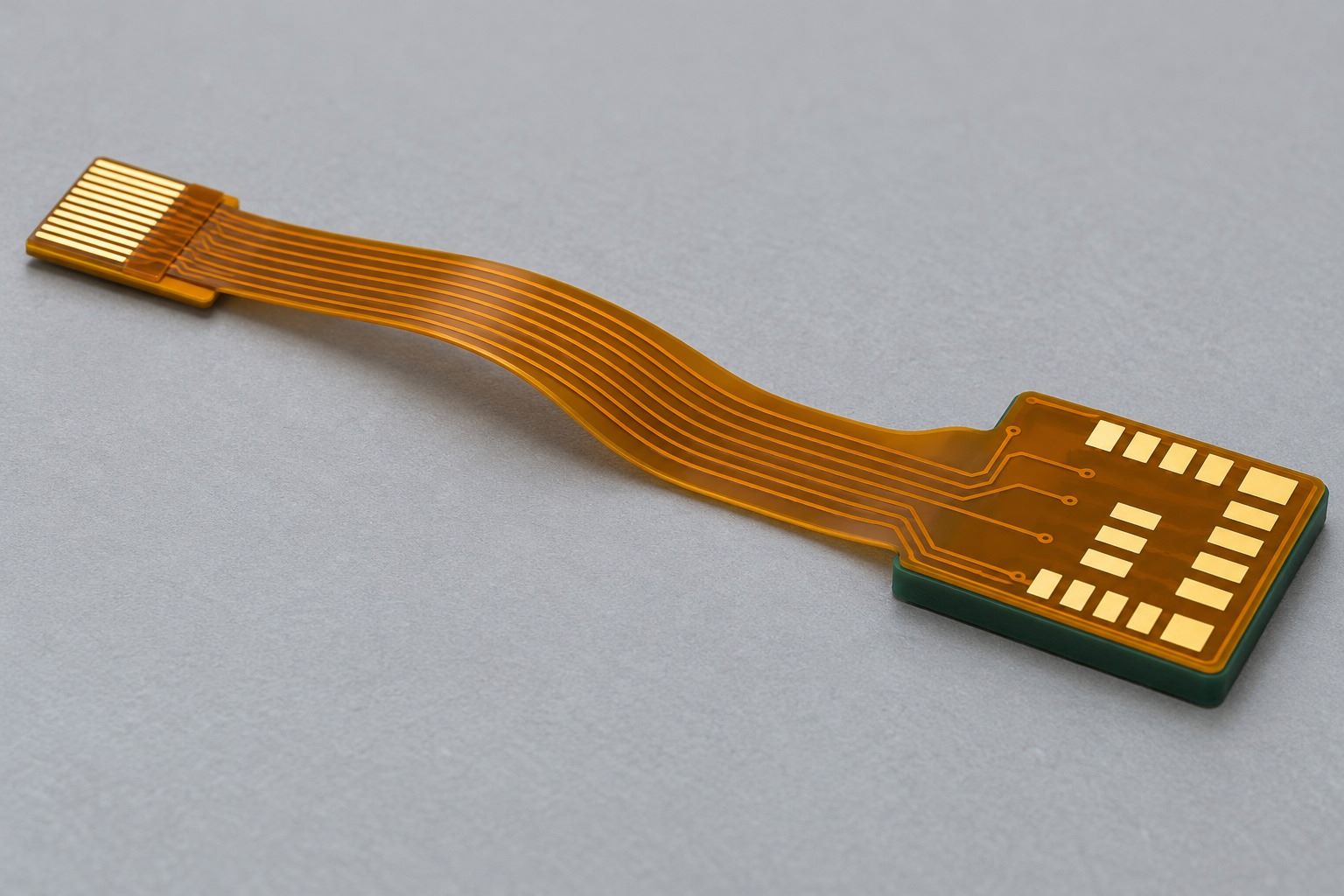
BestFPC's DFM review focuses on whether your double sided flexible circuit can be fabricated, reinforced and assembled as intended. We check your drawings against the intended bend locations, connector interfaces and assembly method.
- Bend regions: Identify where the circuit folds during installation or moves in service. Review vias, solder pads and abrupt geometry changes near those regions.
- Coverlay openings: Check access to solder pads and contact fingers, including registration allowance and the space between adjacent openings.
- Connector fit: Review contact-side orientation, insertion geometry and total tail thickness against the mating connector requirements. These flex connector PCB design considerations are especially important at the ZIF interface.
- Stiffener transitions: Check reinforcement outlines, adhesive thickness and the transition into unsupported flex. Keeping the intended bend clear of an abrupt stiffness change is one consideration in preventing flex PCB delamination.
- Panel preparation: Coordinate tooling features, fiducials and handling support with the intended assembly and separation method.
DFM connects the drawing to the way the circuit will be installed. BestFPC reviews the combined thickness of the FPC, bonding adhesive and stiffener at critical interfaces, so an individually acceptable material choice does not produce an unsuitable finished assembly.
SMT Assembly and Quality Control for Two-Layer Flex PCBs
BestFPC’s flex circuit assembly services combine SMT assembly with component sourcing and inspection options matched to your order. Two copper layers do not automatically require components on both sides; placement depends on the circuit layout and mechanical design.
Assembly planning addresses panel support, local stiffeners and component orientation before soldering. For full turnkey orders, BestFPC can source components; consigned or partial turnkey arrangements can be used when the customer supplies selected parts.
Fabrication and assembly require different checks:
- Incoming materials: Check material specifications, dimensions and condition before use.
- Bare FPC: Use dimensional and visual inspection to assess outlines, openings and reinforcement. Electrical testing checks continuity and isolation.
- SMT process: SPI and AOI support solder-paste and assembly inspection. X-ray inspection is available where hidden joints require examination.
- Order-specific testing: Agree ICT or functional-test requirements, fixtures and acceptance limits before the build.
AOI cannot replace an electrical test, and bare-board continuity does not demonstrate finished-device function. Defining the inspection scope early helps US buyers compare assembly quotations on equivalent terms.
Double-Sided Flexible PCB Manufacturing Case Study for a US Customer
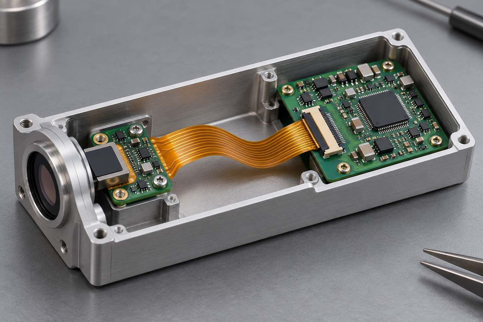
Application: This US customer's two-layer FPC combines a ZIF tail with a reinforced solder-pad area. The construction is suited to a compact industrial sensor module, where it can connect a sensor subassembly to a control board while accommodating their positions inside the enclosure.
Customer Requirements: The customer specified different finished thicknesses at the ZIF interface and solder-pad area. Connector engagement and local assembly support therefore needed separate reinforcement solutions.
Engineering Challenges: Increasing thickness across the entire circuit would compromise flexibility between the interfaces. A conflicting 0.5 mil PI drawing note also needed resolution before the reinforced sections could share a consistent base construction.
BestFPC Solution: The solution combined customer-confirmed 1 mil adhesiveless PI with two local stiffeners: 200 µm PI at the ZIF tail and 800 µm FR-4 beneath the solder pads. The respective finished-thickness requirements were 0.32 ± 0.03 mm and 0.945 ± 0.03 mm.
| Product Parameter | Project Specification |
|---|---|
| Circuit layers | 2 |
| Base material | 1 mil adhesiveless PI |
| Copper | 1/3 oz on L1 and L2 |
| Coverlay | 1/2 mil, yellow |
| ZIF-tail stiffener | 200 µm PI |
| Finished ZIF-tail thickness | 0.32 ± 0.03 mm |
| Pad-area stiffener | 800 µm FR-4 |
| Finished reinforced pad-area thickness | 0.945 ± 0.03 mm |
| Surface finish | ENIG; Au 1–4 µin, Ni 100–200 µin |
| Delivery panel dimensions | 234.80 × 208.00 mm |
Customer Value: Local reinforcement addresses connector fit and solder-pad support without making the entire interconnect rigid. For a compact sensor assembly, this approach allows supported connection points and a flexible routing section to serve different installation needs.
Double-Sided Flex PCB Quotes and Delivery for US Customers
BestFPC prepares quotations around your circuit design, order quantity, assembly needs and US delivery destination. Separating fabrication, optional assembly and freight helps your team evaluate the total purchasing cost and schedule.
The main cost and schedule factors are:
- Materials and finishes: PI grade, copper weight, coverlay and surface finish affect purchasing and processing requirements.
- Outline and panel utilization: Circuit shape, spacing and delivery format influence material usage and handling.
- Reinforcement: Multiple stiffener materials, thicknesses or adhesive locations add preparation and placement requirements.
- Assembly scope: Component availability, placement on one or both sides, fixtures and testing affect the assembled-board quotation.
- Quantity and revisions: Order size affects how tooling costs are shared across the boards. Design changes after approval may require revised tooling or another engineering review.
Send Gerber and drill files, the stackup, dimensions, reinforcement drawings and order quantity. Include the installed bend requirements and any critical connector thicknesses. For assembly, add the BOM, component-placement file and inspection or functional-test requirements.
Manufacturing lead time and arrival time are separate. Request a quotation that identifies the production start conditions, fabrication and assembly schedule, dispatch date and estimated transit time. Provide the US delivery address or ZIP code and clarify shipping terms, freight charges and import-cost responsibility before ordering.
When comparing a double sided flex PCB manufacturer, check that each quotation covers the same materials, finished dimensions, assembly scope and acceptance requirements. A lower initial price is difficult to evaluate if reinforcement, testing or freight is omitted.
FAQs about Double Sided Flex PCB
Does BestFPC manufacture flexible PCBs in the USA?
BestFPC manufactures in China and serves customers in the USA and other international markets. US buyers can request custom flex fabrication, engineering review and optional assembly for delivery to their specified destination.
Does a double sided flex PCB need components on both sides?
No. Double sided refers to the two conductive copper layers. Components may be mounted on one side, both sides or neither side, depending on whether the circuit is used as an assembled board or an interconnect.
How is a double-sided circuit different from a dual-access flex circuit?
A double-sided circuit has two conductive layers. A dual-access circuit provides access to a single conductive layer from both sides through openings in the insulating material. They are different constructions.
Does adding an FR-4 stiffener make the board rigid-flex?
No. A stiffener mechanically supports a flexible circuit without adding a separate routed rigid circuit section. A rigid-flex PCB integrates electrically functional rigid and flexible regions within its construction.
Can two-layer flex PCBs be used for repeated bending?
They can be considered for dynamic applications, but the copper, stackup, bend geometry and required cycle life must be evaluated together. Share the motion requirements before selecting materials or approving the design.
Can BestFPC support prototypes and repeat orders?
Yes. BestFPC offers prototype and production services. Using the same approved stackup, manufacturing files, BOM and inspection requirements helps maintain consistency between repeat orders.
BestFPC combines custom flex fabrication, engineering review and assembly support to help you source circuits that meet your connection, reinforcement and assembly requirements. For a quotation, send your files, quantity and delivery requirements to sales@bestfpc.com.


.png)
.png)
.png)
.png)

.png)