


 2026-10-24

 BEST
A smart ring PCB must fit a narrow, curved enclosure while supporting miniature components and reliable electrical connections. For buyers, the manufacturing challenge is to combine thin flexible sections, stable mounting areas, precise outlines, and an assembly process that protects the finished circuit.
BestFPC supports smart ring PCB projects with flexible and rigid-flex manufacturing, preliminary DFM review, and coordinated component assembly. These services help your team address space constraints, component support, and fabrication requirements before production. Send your Gerber files, mechanical drawings, and quantity requirements to sales@bestfpc.com to discuss a suitable construction and request a quotation.
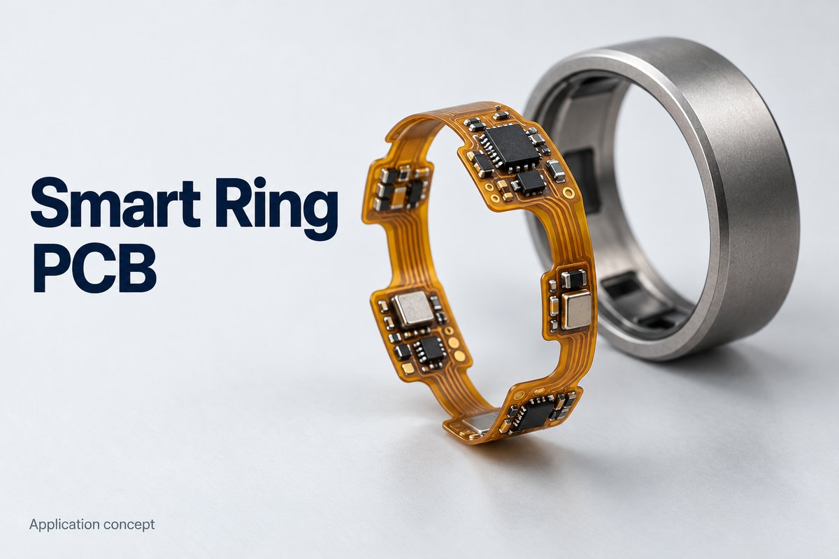
Smart Ring PCB Types Manufactured by BestFPC
BestFPC manufactures single-sided, double-sided, multilayer flexible circuits, and rigid-flex PCBs to customer-approved drawings. For a wearable FPC project, the right construction depends on routing density, available mounting space, and how the circuit will be installed inside the ring.
| PCB Type | Structural Feature | Suitable Requirement |
|---|---|---|
| Single-Sided FPC | One conductive layer | Simple, thin interconnections |
| Double-Sided FPC | Routing on both sides | Compact sensor and power connections |
| Multilayer FPC | Additional routing layers | More complex circuit interconnections |
| Rigid-Flex PCB | Rigid sections with flexible links | Supported component islands |
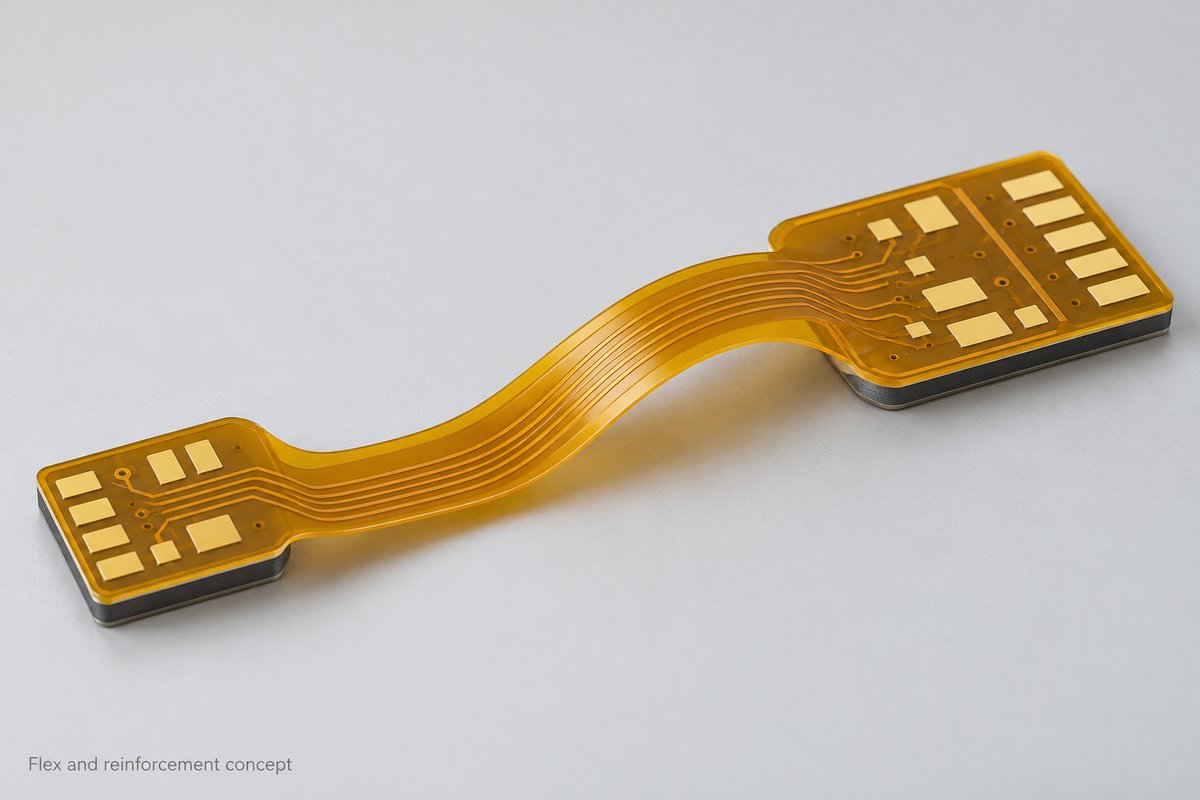
- Reinforced FPC: Local stiffeners support selected components or terminations while retaining flexible connections. They add mechanical support, not additional routing layers.
- Rigid-Flex: Rigid sections support populated areas and provide routing layers connected through flexible regions. This construction suits assemblies with multiple component islands.
BestFPC reviews the outline and mounting arrangement to help match the construction to your ring’s installation space.
Smart Ring PCB Manufacturing Capabilities
BestFPC’s flex PCB fabrication options cover thin constructions, multilayer routing, and local reinforcement. The following manufacturing parameters provide a starting point for evaluating your drawing.
| Manufacturing Parameter | Available Specification | Applicable Condition |
|---|---|---|
| FPC Layer Count | 1–4 layers | Standard FPC process group |
| FPC Finished Thickness | 0.06–0.60 mm | Standard FPC process group |
| Extended FPC Layer Options | 1–6 layers | Separate qualified process group |
| Rigid-Flex Layer Options | 2–10 layers | Same separate process group |
| Rigid-Flex Regional Thickness | Rigid: 0.25–3.0 mm; flex: ≥0.13 mm | Separate process group; stackup dependent |
| Inner-Layer Line / Space | 3 / 3 mil; locally 2.5 / 2.5 mil | 18 μm finished copper; before compensation |
| PI Stiffener Options | 3, 5, 7, or 9 mil | Selected reinforcement areas |
- Construction Matching: BestFPC evaluates layer count, copper, thickness, and transitions together. The table lists separate process options; minimum values do not apply to every construction.
- Critical-Dimension Review: Identify the dimensions that control enclosure fit so manufacturing tolerances focus on the areas that affect assembly.
Flexible PCB Materials and Stackup Options for Smart Rings
BestFPC can review polyimide constructions, adhesive or adhesiveless materials, coverlay, and local stiffeners against your ring’s installation requirements. Flexible PCB material selection should account for the complete assembled thickness, including reinforcement and bonding layers.
- Thin Flexible Sections: Consider the base film, copper, and coverlay together. A thin core alone does not determine the finished circuit thickness.
- Component Support: Define stiffener position and thickness around soldered components, connectors, or charging contacts. Reinforcement should support the joint without obstructing the intended bend.
- Copper Construction: Specify copper thickness and whether the circuit is formed during installation or repeatedly flexed in use. Material selection and bend validation should follow that distinction.
- Rigid-Flex Transitions: Keep the flexible connection and rigid mounting regions clearly identified in the fabrication drawing.
BestFPC reviews the FPC stackup alongside the mechanical drawing before production approval.
Miniature PCB Design and DFM Support for Smart Rings
BestFPC reviews customer designs for fabrication and assembly, focusing on the features that can restrict ring fit or complicate production. The review connects your mechanical requirements with practical manufacturing decisions.
- Fine-Line and Pad Review: We check trace spacing, copper thickness, pad geometry, and coverlay openings together to identify features that need adjustment before fabrication.
- Bend-Zone Review: We assess the specified flex PCB bend radius, forming direction, reinforcement edges, and nearby solder joints. For rigid-flex constructions, the review also covers the flex-region stackup and transition geometry.
- Mechanical Clearance Review: We compare the board outline, stiffener locations, and component-height requirements with your mechanical drawings to identify potential assembly interference.
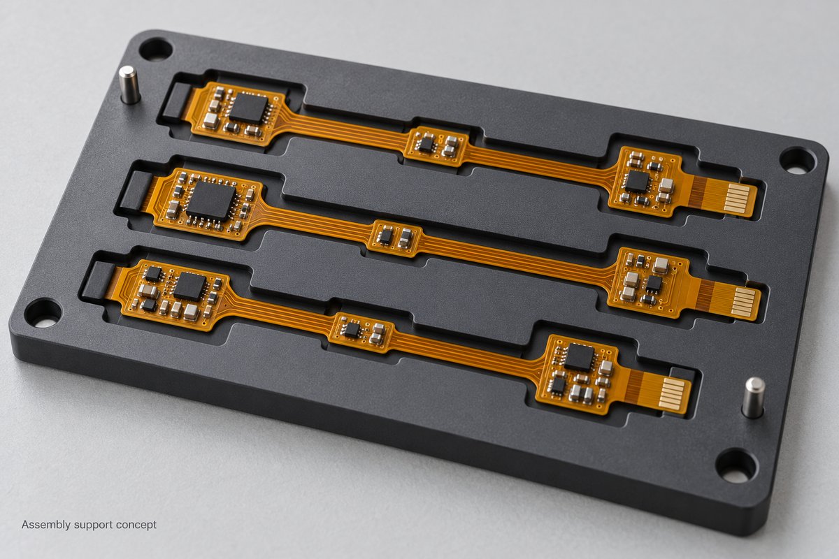
- Production Preparation: We review panel support, tooling, fiducials, and inspection access so fabrication and SMT requirements are addressed before release.
The service covers manufacturability and assembly preparation; original circuit design, antenna tuning, and firmware development require a separate scope.
Smart Ring Flexible PCB and Rigid-Flex Assembly Services
BestFPC provides flex circuit assembly services for customers purchasing populated FPCs or rigid-flex boards. Fabrication, sourcing, assembly, and inspection can be coordinated through one manufacturing partner.
- Component Sourcing: We support component procurement and BOM review, checking part numbers, packages, and availability. Substitutions are submitted for approval so changes remain compatible with your electrical and mechanical requirements.
- SMT Assembly: We provide miniature-component placement and soldering for flexible and rigid-flex circuits. Package and placement requirements are reviewed against the assembly process before the build starts.
- Flexible PCB Assembly Support: Carrier, fixture, and positioning requirements are planned around the thin circuit. This gives printing and placement operations stable support while protecting the flex sections during handling.
- Rigid-Flex PCB Assembly: Assembly preparation addresses the rigid component areas, board orientation, and support near flexible transitions. The aim is to avoid transferring unnecessary handling loads into bends and solder joints.
- Turnkey & Consigned Assembly: Choose full turnkey sourcing, partial turnkey, or customer-supplied components. The supply arrangement can follow your purchasing strategy and existing component inventory.
- Inspection & Testing: First-article review, solder-joint inspection, and project-defined testing help check the assembly before shipment. Inspection methods and functional acceptance criteria are agreed with your order.
Quality Control and Testing for Smart Ring PCBs
BestFPC’s quality control process includes incoming checks, in-process inspection, and electrical testing before board delivery. For a ring project, acceptance criteria should address the dimensions and connections that matter inside the finished enclosure.
- Bare-Board Verification: Electrical testing checks continuity and isolation. Dimensional and visual checks address the outline, coverlay openings, and reinforcement placement against the approved drawing.
- Assembly Inspection: First-article review checks the initial build against approved files. SPI, AOI, and X-ray can be selected for the package types and solder connections involved.
- Functional Testing: Ordered tests follow agreed power-up, sensor-communication, or other functional criteria. Defining fixtures and pass/fail limits gives customers a clear acceptance basis.
- Mechanical Validation Planning: Flexible PCB reliability testing requires a defined installation shape and, where relevant, bend cycles. Agree the method and responsibility for each rigid flex PCB reliability test before production.
Bare-board electrical testing does not establish finished-ring waterproofing, wireless performance, or battery life. Those results require validation of the assembled product under its intended conditions.
Smart Ring PCB Manufacturing Case Study
Application: This manufacturing example uses a thin two-layer FPC for sensor-to-control-board connections inside a smart ring. The flexible section follows the housing contour, while locally reinforced areas support component or termination locations.
Manufacturing Challenges:
- Limited Internal Clearance: The interconnect must share a narrow installation space with the battery, sensors, and housing features.
- Thin-Board Assembly: Flexible material needs stable support during printing, placement, and soldering.
- Localized Reinforcement: Mounting areas need stiffness without extending reinforcement into the intended forming region.
BestFPC Manufacturing Solutions:
- Thin Adhesiveless Construction: The selected specification combines 20 μm adhesiveless PI and 20 μm ED copper, with a finished flex-region thickness of 0.11 ± 0.03 mm. This provides a thin construction for reviewing the ring’s internal routing space.
- Separate Reinforcement Zones: The board specifies 0.20 mm and 0.30 mm stiffeners. BestFPC can adapt their locations to the approved mounting drawing, supporting connection areas while leaving the defined flex section free to form.
- Coordinated Fabrication and SMT: Yellow coverlay protects the circuitry, and ENIG provides the specified solderable finish. Panel support and production files are reviewed before SMT to align board handling with the assembly requirements.
Customer Benefits: The combination of a thin interconnect and local reinforcement gives customers a practical way to accommodate curved routing and supported mounting areas. Coordinating fabrication and SMT also helps resolve handling and fit requirements before prototype release.
PCB Specifications:
| PCB Parameter | Specification |
|---|---|
| Construction | 2-layer FPC |
| Base Material | 20 μm adhesiveless PI |
| Copper | 20 μm ED copper |
| Coverlay | ½ mil, yellow |
| Flex-Region Thickness | 0.11 ± 0.03 mm |
| Stiffener 1 Thickness | 0.20 mm, stiffener only |
| Stiffener 2 Thickness | 0.30 mm, stiffener only |
| Surface Finish | ENIG; gold specified at 1 μin |
| Silkscreen | White |
| Assembly Requirement | SMT assembly |
Smart Ring PCB Manufacturing Cost and Lead Time
Smart ring PCB cost depends on the approved construction and delivery scope. BestFPC can evaluate prototype and production quantities separately so buyers can compare tooling, materials, fabrication, and assembly on the same basis.
- Layer Structure: Additional routing layers and rigid-flex lamination increase process requirements.
- Circuit Geometry: Fine lines, small interconnections, and demanding registration can affect manufacturing difficulty.
- Outline and Panel Utilization: Small individual boards do not necessarily produce the lowest unit cost when panel waste or handling requirements are high.
- Assembly and Verification: Component sourcing, support fixtures, hidden joints, and functional test development affect the complete PCBA quotation.
Compare flex PCB cost and rigid flex PCB cost using the same function, quantities, and acceptance criteria. BestFPC confirms lead time after reviewing files, material and component availability, and testing requirements; production and transit time are quoted separately where applicable.
Why Choose BestFPC as Your Smart Ring PCB Manufacturer?
BestFPC gives smart ring developers access to flexible and rigid-flex fabrication, manufacturing review, and assembly support in China. Customers can discuss board construction and PCBA requirements with one manufacturing partner.
- Product Options for Different Mounting Needs: Single-sided, double-sided, multilayer FPC, and rigid-flex constructions allow the build to follow your routing and support requirements.
- Manufacturing Review Before Release: BestFPC checks thin sections, reinforcement, transitions, and assembly preparation to identify problems while drawing changes are still practical.
- PCB and Component Coordination: Fabrication files, component packages, sourcing, and test requirements are reviewed together, reducing the risk of mismatches between the bare board and assembled product.
- Support from Samples to Repeat Orders: Prototype and production services allow subsequent builds to follow the approved revision, material requirements, and acceptance criteria.
How to Get a Quote for Smart Ring PCBs?
Send a complete manufacturing package to sales@bestfpc.com for a smart ring PCB quotation. Include the installation drawing as well as the flat circuit files so the review addresses the finished assembly space.
For a flex PCB quote, provide:
- Fabrication Files: Gerber or ODB++, drill data, outline, and drawing revision.
- Construction Requirements: Layer count, stackup, copper, surface finish, coverlay, and stiffeners.
- Mechanical Constraints: Bend regions, installation shape, critical dimensions, and component-height limits.
- Order Requirements: Prototype quantity, expected production quantities, destination, and target delivery date.
- PCBA Requirements: BOM, placement data, sourcing arrangement, and inspection or functional test instructions.
If a dimension or construction remains undecided, identify it in your request so the engineering review can focus on that question.
FAQs About Smart Ring PCB Manufacturing
How thin can a smart ring PCB be?
The appropriate flex PCB thickness depends on its layer count, copper, coverlay, and reinforcement. BestFPC’s standard FPC process range includes 0.06–0.60 mm, but the minimum is not available for every construction. Specify flexible and reinforced regions separately.
Does a smart ring always need a rigid-flex PCB?
No. A reinforced FPC may suit the mounting arrangement. Rigid-flex is an option when rigid component sections and flexible interconnections are needed within one board structure.
Can the copper thickness be changed to improve flexibility?
Flexible PCB copper thickness must also satisfy electrical and fabrication requirements. Any change should be reviewed with the stackup, trace geometry, and bending conditions before production approval.
Can BestFPC supply assembled boards?
Yes. Request PCB fabrication with component sourcing and assembly, or specify a partial turnkey or consigned-component arrangement. Include the BOM, placement file, and test requirements.
Is functional testing automatically included?
Functional testing must be defined in the order scope. Bare-board electrical testing and solder-joint inspection do not replace a product-specific functional test.
BestFPC helps customers coordinate flexible circuit manufacturing, rigid-flex construction, and assembly requirements for compact products. Send your design files and quantities to sales@bestfpc.com to discuss your smart ring PCB project and request an engineering review and quotation.


.png)
.png)
.png)
.png)

.png)