


 2026-10-23

 BEST
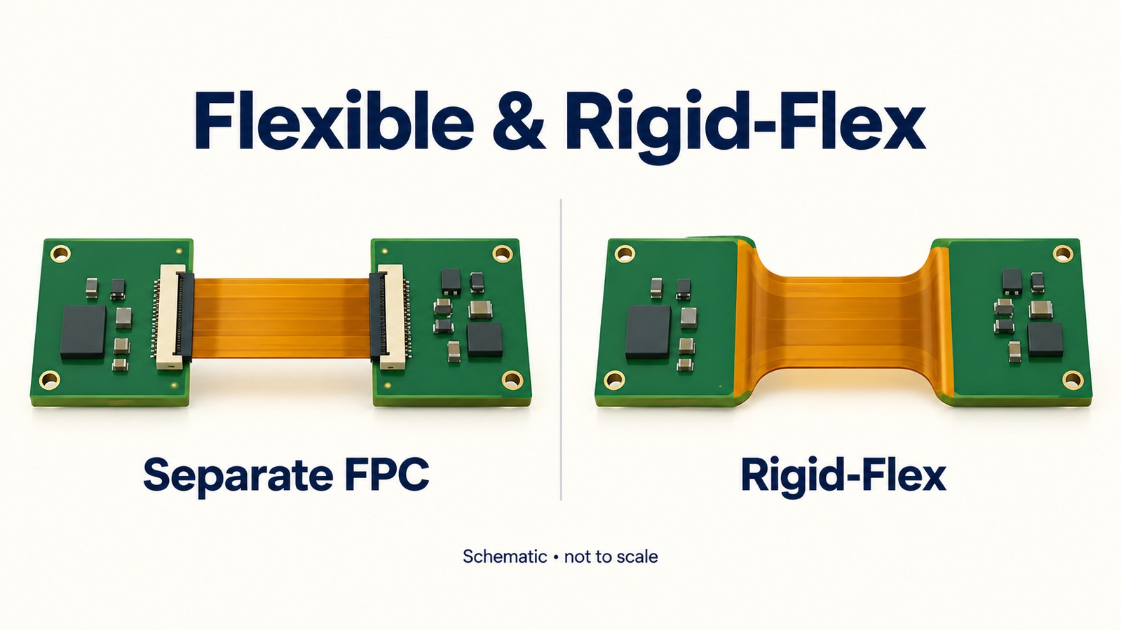
Smartwatch PCB manufacturing brings together thin interconnects, compact board structures, and precise connector interfaces. Separate FPCs can link a rigid mainboard to the display or other modules, while rigid-flex combines rigid sections and flexible connections in one board. Both approaches require a stackup that fits the enclosure and supports assembly.
BestFPC manufactures flexible and rigid-flex PCBs and provides DFM review and assembly support for compact electronics. Our team helps you match board construction, connector interfaces, and reinforcement to your smart watch PCB requirements. Contact sales@bestpcbs.com with your drawings to discuss fabrication options, resolve manufacturing details, and obtain a quotation covering the services your project needs.
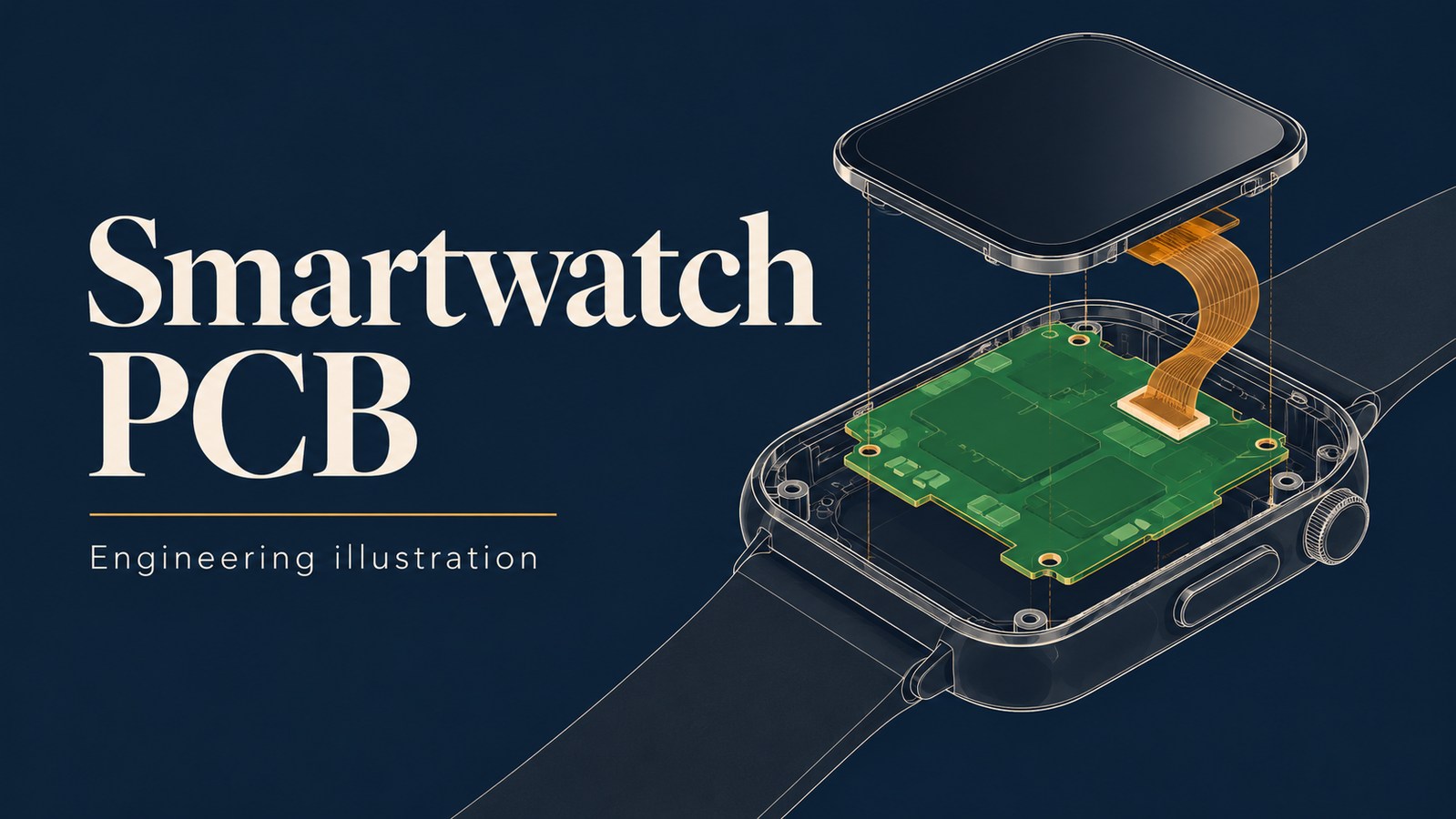
Smartwatch PCB Types Manufactured by BestFPC
BestFPC manufactures 1–4-layer flexible circuits and 2–20-layer rigid-flex boards. We supply separate FPC interconnects for rigid mainboards as well as integrated rigid-flex constructions, helping your team match the board structure to display connections, module placement, and assembly access.
| PCB Type | Manufacturing Features | Suitable Application |
|---|---|---|
| Rigid PCB + separate FPC | Separate mainboard and flexible interconnect | Mainboard-to-display connections |
| Flexible PCB | Thin flexible section; local reinforcement | Module connections through narrow spaces |
| Rigid-Flex PCB | Integrated rigid and flexible sections | Connected boards within one assembly |
| Multilayer Flexible PCB | Additional routing layers | Interconnects with greater routing needs |
Separate FPCs allow the mainboard and interconnect to be manufactured and assembled independently. This arrangement suits designs with accessible mating interfaces and a defined path for the flexible section.
Rigid-flex can replace some separate board-to-board connections with integrated flexible sections. The rigid areas support components, while the flexible sections accommodate the installed arrangement.
Multilayer FPC adds routing capacity where the circuit needs it. Our engineers review the resulting thickness and intended movement alongside the electrical requirements, helping you select a construction that fits both the circuit and assembly space.
Smartwatch PCB Manufacturing Capabilities
BestFPC offers 1–4-layer FPC and 2–20-layer rigid-flex PCB manufacturing within the standard ranges below. Thin flexible constructions, fine inner-layer circuitry, and local reinforcement give designers options for compact interconnects and component-support areas.
Flexible PCB
| Parameter | Manufacturing Specification |
|---|---|
| Layer Count | 1–4 layers, standard range |
| Board Thickness | 0.06–0.60 mm, standard range |
| Inner-Layer Trace / Space | 3/3 mil; 18 μm finished copper; before compensation |
| Mechanical Drill Size | 0.15 mm at board thickness ≤1.6 mm |
| PI Stiffener Options | 3, 5, 7, or 9 mil |
| Surface Finish Options | ENIG, gold plating, OSP, tin plating |
Rigid-Flex PCB
| Parameter | Manufacturing Specification |
|---|---|
| Layer Count | 2–20 layers, standard range |
| Board Thickness | 0.3–3.0 mm, standard range |
| Inner-Layer Trace / Space | 3/3 mil; 18 μm finished copper; before compensation |
| Rigid Outer-Layer Trace / Space | 3.5/3.5 mil; 18 μm finished copper; before compensation |
| Flex Outer-Layer Trace / Space | 5/4.5 mil; 18 μm finished copper; before compensation |
| Mechanical Drill Size | 0.15 mm at board thickness ≤1.6 mm |
These are individual process ranges. Our engineers confirm the achievable combination for your material, copper thickness, and stackup. Mechanical drill size refers to the drill-tool diameter, with finished plated-hole dimensions specified separately.
Identify critical mating dimensions on the fabrication drawing. This lets us focus the manufacturing review on the thicknesses, openings, and tolerances that affect installation.
Smartwatch PCB Design & DFM Support
Our engineers review stackup, circuit geometry, connector interfaces, and fabrication tolerances before production. This DFM support helps turn your smartwatch PCB design into manufacturing files with clear material, dimensional, and assembly requirements.
A smart watch PCB design review covers:
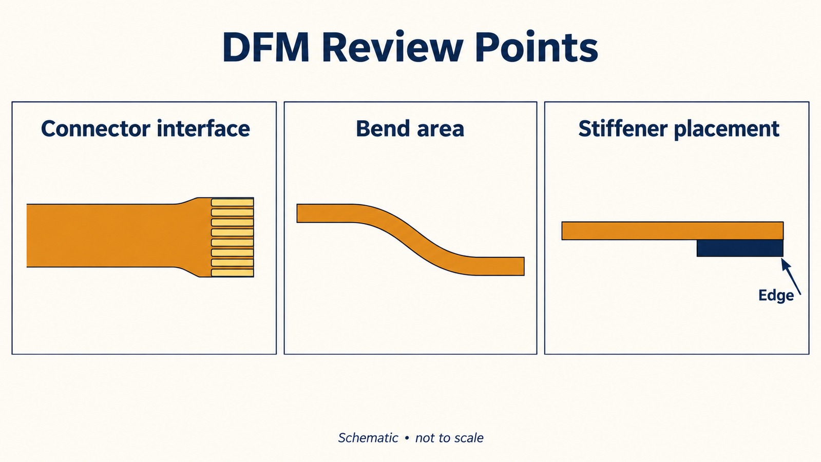
- Component clearance: We compare component areas with board edges, coverlay openings, and assembly access to identify interference in the supplied layout.
- Bend areas: We review the intended flexible regions and routing against the stackup and installed shape. Tell us whether bending occurs during installation or repeatedly in service.
- Connector interfaces: Contact orientation, exposed-pad geometry, and finished insertion thickness are checked against the mating drawing.
- Rigid-flex transitions: The review addresses conductors, holes, and components near the transition between rigid and flexible sections.
- Stiffener placement: Reinforcement boundaries are checked against connector engagement, soldering areas, and sections that need to remain flexible.
- Dimensional tolerances: We focus on dimensions that control enclosure fit, alignment, and connector assembly.
Provide the flat outline and installed geometry together. Our engineers can then discuss fabrication adjustments in the context of the actual assembly, rather than treating the board as an isolated flat part.
Before production, we confirm the fabrication requirements and coordinate approved changes across the board files, BOM, and assembly drawings.
FPC Connectors, Stiffeners & Stackup Options for Smartwatches
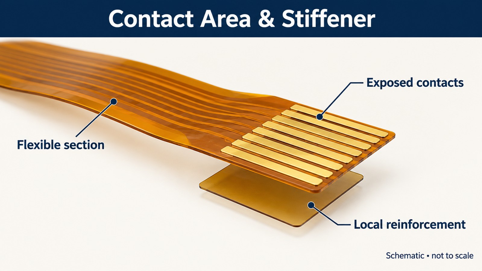
A flexible-circuit connection needs matching contact orientation, insertion thickness, contact geometry, and space to operate the latch. BestFPC helps align the FPC construction with these interface requirements so the flexible section and reinforced contact area serve their intended functions.
Connector contact orientation and thickness. Specify which side carries the exposed contacts and the connector's required insertion thickness. The mating thickness includes the applicable circuit layers, adhesive, and reinforcement; it is different from the stiffener thickness alone.
PI, copper, and coverlay. Our engineers review these layers together to establish the flexible-section thickness and required openings. Specify exposed contacts and soldering pads in the artwork so coverlay protection and assembly access match your design.
Local reinforcement. BestFPC offers PI stiffener options of 3, 5, 7, and 9 mil. We review the selected reinforcement against the required mating thickness and contact geometry, keeping its boundaries clear of sections intended to bend.
Rigid-flex construction. Show the rigid-section boundaries and installed orientation. The bend requirements are reviewed against the selected materials, total construction, and expected movement, keeping the mechanical and fabrication requirements aligned.
Smartwatch PCB Assembly & Quality Control
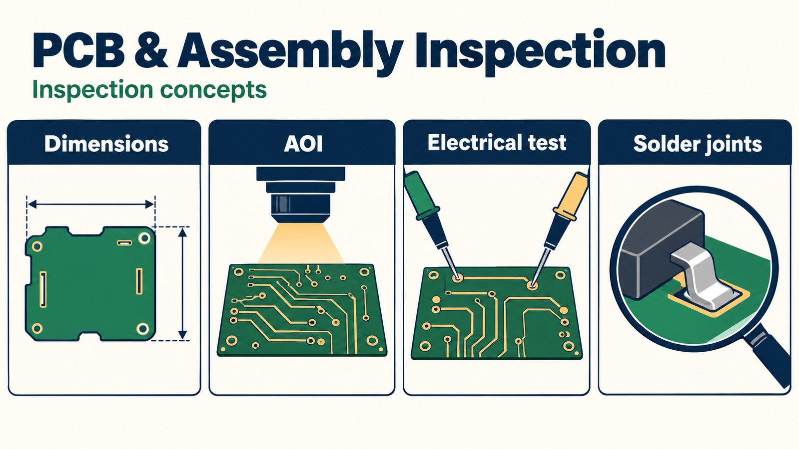
BestFPC uses process inspection, AOI, and electrical testing to check PCB manufacturing quality. Our PCBA service coordinates component sourcing and SMT assembly with checks for component placement, solder joints, and cleanliness according to the order requirements.
| Inspection Method | Inspection Focus |
|---|---|
| Fabrication inspection | Outline, openings, reinforcement, workmanship |
| AOI | Circuit-pattern inspection |
| Bare-board electrical testing | Circuit opens and shorts |
| Assembly inspection | Component placement, solder joints, cleanliness |
For bare boards, the fabrication package defines the dimensions and construction to inspect. For assembled circuits, the BOM and assembly drawings establish component identities, orientation, and soldering requirements. Keeping these files aligned gives engineering and purchasing teams a clear basis for acceptance.
If your project requires functional testing, include the procedure, acceptance limits, and fixture or firmware requirements in the inquiry. Our team will confirm the available testing scope during quotation.
PCB electrical testing does not verify smartwatch waterproofing, battery runtime, sensor accuracy, or RF performance. These require product-level validation. Separating board, assembly, and complete-device tests makes the quotation scope clear from the outset.
Smartwatch PCB Manufacturing Case Study
Application & Project Requirements
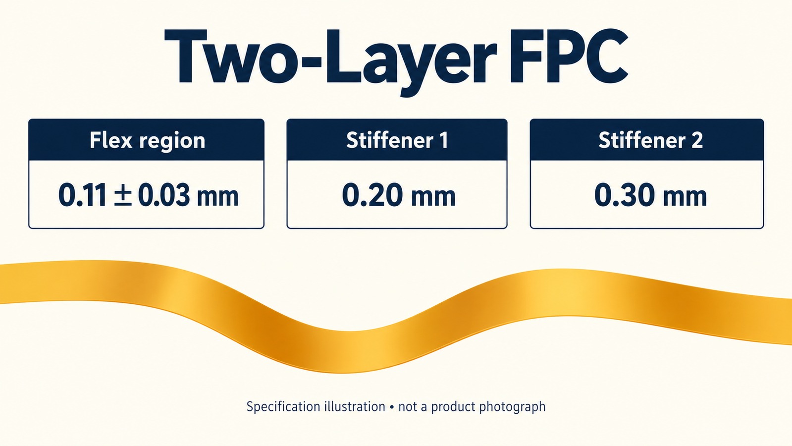
BestFPC's two-layer FPC combines a 0.11 ± 0.03 mm flexible region with 0.20 mm and 0.30 mm stiffeners and SMT requirements. For a smartwatch display connection, this construction offers a candidate for thin routing with local support. Selection requires matching the board to the display interface and installed geometry.
Manufacturing Challenges
- Controlling the thin flexible section while incorporating two reinforcement thicknesses.
- Aligning circuit, component, and assembly requirements through design revisions.
- Maintaining soldering quality and cleanliness on the assembled flexible board.
BestFPC Manufacturing Solutions
- Stackup confirmation: The production package specifies the PI, copper, coverlay, flexible-region thickness, and reinforcement requirements. Customer confirmation of the layer structure and production data precedes fabrication.
- Fabrication and assembly coordination: Approved FPC and BOM revisions are aligned before production. When adapting this construction to a display connection, the mating thickness and reinforcement boundaries need to be checked against the connector drawing.
- Assembly inspection: The SMT requirements include careful solder-joint checks and a clean board surface free of solder balls and other residues. This board's assembly scope covers SMT and inspection, with functional testing excluded.
Key PCB Specifications
| Parameter | PCB Specification |
|---|---|
| Layer Count | 2 layers |
| Base Material | 20 μm adhesiveless PI |
| Copper | 20 μm ED copper |
| Coverlay | 1/2 mil yellow coverlay |
| Flex-Region Thickness | 0.11 ± 0.03 mm |
| Stiffener Thicknesses | 0.20 mm / 0.30 mm |
| Surface Finish | ENIG, Au 1 μin |
| Silkscreen | White |
| Assembly Requirement | SMT required |
Application Value
The thin section provides a compact interconnection path, while local stiffeners add support at designated areas. For display integration, engineers can evaluate this combination against available space, interface dimensions, and electrical requirements without adding reinforcement throughout the flexible section.
Smartwatch PCB Manufacturing Cost & Lead Time
BestFPC offers flexible PCB manufacturing in approximately 1.5 weeks, together with fast-turnaround PCBA services. We confirm each FPC schedule against board construction, quantity, complete production files, and material availability. Rigid-flex and special-process orders receive project-specific schedules.
Fast Manufacturing & Assembly Support
- Approx. 1.5-week FPC manufacturing: Submit board requirements and your target date to confirm the production schedule.
- Fast-turnaround PCBA: Coordinate PCB fabrication, component sourcing, SMT assembly, and assembly inspection through BestFPC, reducing handoffs between separate suppliers. Timing is confirmed from the BOM, component availability, board structure, and assembly requirements.
- Engineering support for cost optimization: Our team reviews construction, stackup, and panelization options against your design requirements.
- Prototype-to-production support: Discuss prototype quantities and expected production volumes together to plan purchasing and subsequent builds.
How to Control Smartwatch PCB Manufacturing Costs
- Compare total assembly cost: Separate FPCs and rigid-flex differ in fabrication complexity, connector requirements, and assembly work. Compare the complete build before choosing either structure.
- Specify the construction you need: Ask engineering to review layer count, copper thickness, and material options that meet the electrical and mechanical requirements. Additional layers or special materials can increase processing and purchasing costs.
- Coordinate panels, quantities, and sourcing: Share quantity breaks and assembly-panel constraints for panelization review. Provide a complete BOM and approved substitution options so component availability and assembly requirements can be included in the cost comparison.
Send Gerber files, BOM, quantities, and your target delivery date to sales@bestpcbs.com for a manufacturing and assembly quotation.
Why Choose BestFPC for Smartwatch PCB Manufacturing?
BestFPC combines flexible PCB fabrication, rigid-flex manufacturing, DFM support, and assembly coordination for compact electronic designs. These services help engineers resolve construction details and give purchasing teams a defined manufacturing scope.
- Thin flexible interconnects: Our 0.06–0.60 mm FPC range provides options for routing between modules where installation space is limited. Local reinforcement supports connector or component areas while preserving the intended flexible sections.
- Flex and rigid-flex manufacturing: We support separate interconnects and integrated constructions, giving your team a choice based on connection count, enclosure layout, and assembly access.
- Fine-line fabrication: 3/3 mil inner-layer trace/space at 18 μm finished copper, before compensation, supports compact routing. Our engineers match this capability to your stackup and layer requirements.
- DFM support: Our engineers address stackup, connector interfaces, reinforcement, and critical dimensions before fabrication, helping resolve issues that could otherwise reach assembly.
- Fast PCBA coordination: Fabrication, component sourcing, SMT, and assembly inspection can be coordinated through BestFPC, reducing communication and handoffs between separate suppliers. Your BOM and build requirements establish the delivery schedule.
- Prototype-to-production support: We support prototype builds and subsequent production orders, reviewing quantities, materials, and inspection requirements as the project progresses.
If you are changing suppliers, share the existing drawings and the problem you need to solve—such as insertion thickness, reinforcement placement, or assembly fit. This gives our engineers a specific starting point for improving manufacturability.
How to Get a Smartwatch PCB Manufacturing Quote?
BestFPC provides fabrication quotations and engineering review for flexible and rigid-flex projects, with assembly included when required. To prepare a quotation, send:
- Gerber files and fabrication drawings, identifying the current revision.
- Stackup and material requirements, including copper and finished thicknesses.
- BOM and placement data for assembled orders.
- Connector and stiffener requirements, including mating dimensions and installed geometry.
- Order quantity and delivery requirements, together with inspection or testing needs.
For other file formats, confirm compatibility when submitting your package. Highlight any open design questions so engineering can address them alongside the quotation.
Email sales@bestpcbs.com for stackup and interface review, a fabrication or PCBA quotation, and schedule confirmation against your target delivery date.
FAQs About Smartwatch PCB Manufacturing
Can a smartwatch use a separate flexible PCB instead of rigid-flex?
Yes. A separate FPC can connect independently assembled modules when the enclosure provides suitable routing space and access to the mating interfaces. Check the installation sequence when making the change.
Can an FPC connect directly to a ZIF connector?
Yes, when its contacts and finished insertion thickness match the connector drawing. Confirm contact orientation, engagement length, and reinforcement requirements as well as pitch.
Are stiffeners required on every smartwatch flexible circuit?
No. Add reinforcement where a connector or component area needs support. Sections intended to bend should retain the flexibility required by the installed design.
Can BestFPC supply bare flexible PCBs without assembly?
Yes. Request bare-board fabrication in your inquiry. Component procurement and SMT can be quoted separately if you need them later.
Can PCB electrical testing verify smartwatch waterproofing?
No. It checks board connectivity. Waterproofing requires a suitable test of the assembled enclosure and its sealing features.
Bring your fabrication and assembly requirements to BestFPC for thin FPC interconnects, rigid-flex manufacturing, and practical DFM support. Contact sales@bestpcbs.com to discuss the construction, manufacturing scope, and quotation for your next build.


.png)
.png)
.png)
.png)

.png)