


 2026-10-23

 BEST
BestFPC provides pulse oximeter pcb fabrication and SMT assembly for OEM designs, including rigid control boards, flexible sensor interconnects, and rigid-flex assemblies. Manufacturing support covers circuit geometry, board dimensions, connector interfaces, and component assembly to help customers move from design files to production-ready boards.
BestFPC combines flexible and rigid-flex manufacturing, component sourcing, and SMT assembly, with fast-turn PCBA available in as little as 1.5 weeks for eligible projects. Engineers can coordinate board and assembly requirements together, while purchasing teams receive a quotation covering the selected scope. Send your drawings and requirements to sales@bestpcbs.com for a manufacturing review.
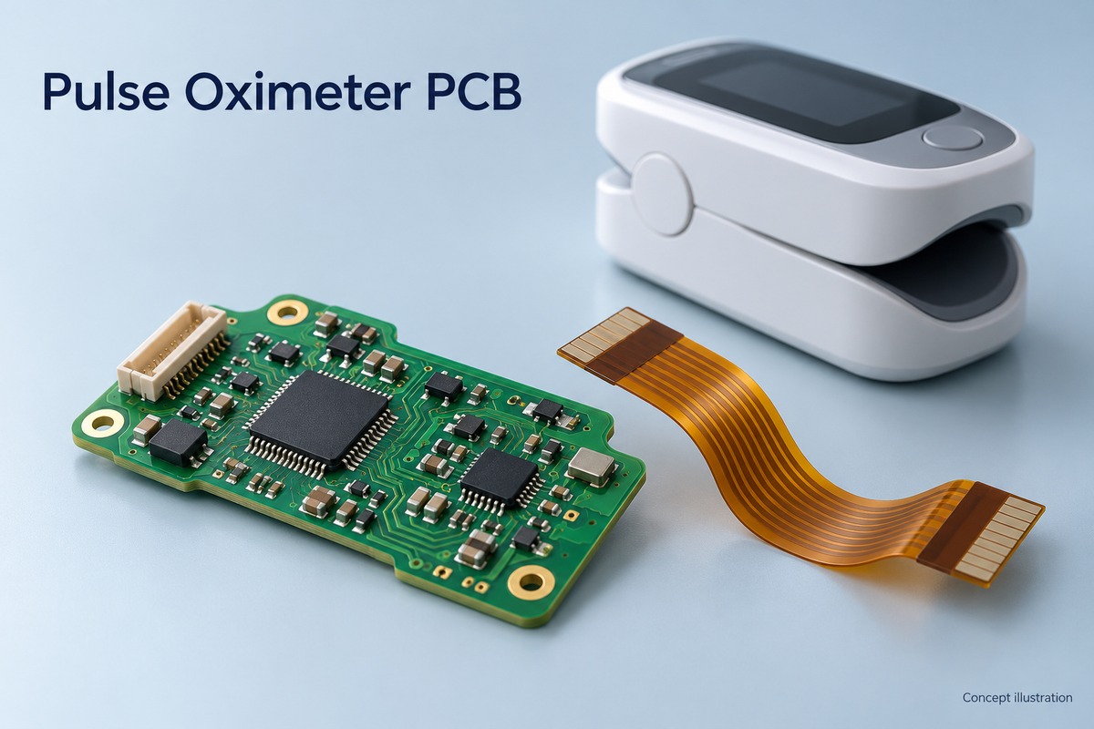
Pulse Oximeter PCB Types Manufactured by BestFPC
BestFPC offers rigid PCBs, flexible PCBs, and rigid-flex PCBs for pulse oximeter designs, covering main-board electronics, optical sensor interconnections, and integrated board assemblies.
| PCB Type | Applications in Pulse Oximeters |
|---|---|
| Rigid PCB | Main control circuitry, LED drivers, analog signal processing, and power management |
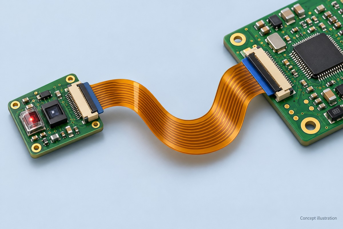
| Flexible PCB (FPC) | Optical sensor-to-main-board interconnections and electrical routing between separated assemblies |
| Rigid-Flex PCB | Integrated rigid sections for control or sensor circuitry, connected by flexible sections within the housing |
Pulse Oximeter PCB Manufacturing Capabilities
BestFPC supports 1–4-layer flexible PCBs and 2–20-layer rigid-flex PCBs, with construction options for thin interconnects and multilayer assemblies. The following parameters provide a starting point for stackup and fabrication review.
| Manufacturing Parameter | Flexible PCB | Rigid-Flex PCB |
|---|---|---|
| Layer count | 1–4 layers | 2–20 layers |
| Board thickness | 0.06–0.60 mm | 0.3–3.0 mm |
| Inner-layer line/space1 | 3/3 mil | 3/3 mil |
| Outer rigid-layer line/space1 | Not applicable | 3.5/3.5 mil, with rigid layers on top and bottom |
| Mechanical drill diameter2 | 0.15 mm, subject to the ≤1.6 mm thickness condition | 0.15 mm, subject to the ≤1.6 mm thickness condition |
| Adhesiveless core base copper | 0.33, 0.5, 1, or 2 oz | 0.33, 0.5, 1, or 2 oz |
| Surface finish options | Immersion gold, plated gold, OSP, tin plating | Immersion gold, plated gold, OSP, tin plating |
1 Line/space values apply to 18 μm finished copper before manufacturing compensation. Inner-layer limits do not apply to external flex layers. Base copper weight and finished copper thickness must be specified separately.
2 A 0.20 mm mechanical drill is also available under the ≤2.5 mm thickness condition. The applicable thickness and stackup require engineering confirmation. Drill diameter is different from finished plated-hole diameter.
FPC laser profiling supports a 0.1 mm outline tolerance, with acceptance limits agreed on the fabrication drawing. Layer count, thickness, copper, and minimum features must be reviewed as one construction; individual capability limits cannot automatically be combined.
Pulse Oximeter Circuit Design and PCB Layout
For a pulse oximeter circuit, prioritize the photodiode input path, LED switching loops, and their relationship to the analog front end. These areas deserve attention before routing density drives the layout.
- Keep receiver inputs away from switching activity. Place the analog front end near the photodiode connection where practical. Avoid parallel routing alongside clocks, LED drive traces, and power-converter switching nodes.
- Control LED and power-current loops. Keep switching loops compact and place decoupling according to the selected device’s requirements. Consider the return-current path as carefully as the outgoing trace.
- Coordinate grounding with component placement. Follow the analog front end’s grounding recommendations. Avoid ground splits that force sensitive signals or their return currents across discontinuities.
- Check the sensor interface before release. Confirm connector pinout, footprint, polarity, and mechanical alignment against the selected sensor and enclosure.
- Include manufacturing clearances in the layout rules. Check pad spacing, coverlay openings, trace-to-edge clearance, and solder access using the actual layer construction.
BestFPC’s engineering review can address fabrication and assembly constraints in the submitted design. Electrical performance and SpO2 accuracy remain part of the OEM’s complete system validation.
Flexible PCB and Rigid-Flex Solutions for Pulse Oximeters
BestFPC’s flex engineering review focuses on installed geometry, connector support, and bend requirements. These details determine whether a circuit that fits the flat drawing will also fit and assemble correctly inside the product.
Define the installed shape. Supply the flat outline together with a drawing showing the assembled position. Mark bends, housing contact points, and areas where the circuit must remain flat. This helps identify pinching, excessive slack, or a forced fold during enclosure assembly.
Specify the connector interface as a complete stack. The connector’s required mating thickness includes the relevant FPC layers, adhesive, and stiffener. Define the contact side, insertion direction, stiffener position, and thickness tolerance together.
Separate static bending from repeated movement. A circuit bent once during installation has different requirements from an interconnect that moves each time a finger clip opens. Identify the movement, bend direction, and expected use so the copper and stackup can be assessed accordingly.
Keep rigid-flex transitions clear. Locate component mounting, solder joints, and mechanical constraints away from the intended flexing region. Review the rigid-to-flex boundary before fixing nearby connector or housing features.
Bend radius and flex-life requirements should be established for the selected construction and validated under the intended movement.
Pulse Oximeter PCB Assembly Services
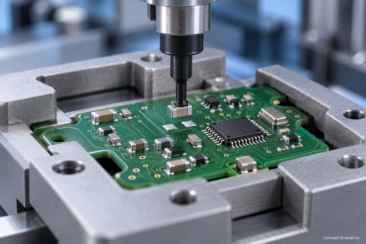
BestFPC provides SMT, THT, and mixed assembly for rigid, flexible, and rigid-flex PCBs, with placement capabilities covering 01005 SMD components and 0.25 mm-pitch BGAs. These capabilities support miniature passives and fine-pitch devices used in compact pulse oximeter board assemblies.
| Assembly Capability | BestFPC Specifications |
|---|---|
| Placement capacity | 13,200,000 chips/day |
| Minimum SMD component | 01005 |
| Minimum BGA pitch | 0.25 mm |
| Assembly processes | SMT, THT, mixed assembly |
| Supported PCB types | Rigid PCB, flexible PCB, rigid-flex PCB |
| Component packaging | Reels, cut tape, tube, tray, loose parts |
For pulse oximeter projects, BestFPC supports miniature component placement, fine-pitch IC assembly, and connector soldering. Flexible boards receive carrier or fixture support coordinated with their reinforced assembly areas to stabilize printing and placement. Post-assembly solder-joint inspection and customer-specified electrical or functional testing can be included in the agreed build scope.
Turnkey, partial turnkey, and consigned-component arrangements are available for prototype and production orders.
Quality Control and Testing for Pulse Oximeter PCBs
BestFPC uses incoming inspection, in-process inspection, AOI, and bare-board electrical testing to control fabrication quality. Assembly inspection and additional testing are selected around the components, accessible features, and customer acceptance requirements.
Fabrication checks address critical dimensions, conductor patterns, pad exposure, surface condition, and coverlay or solder-mask registration. Bare-board electrical testing checks for opens and shorts.
Flex-specific checks address stiffener position, bend-zone geometry, and visible damage. Connector regions should be assessed against the finished interface dimensions rather than stiffener thickness alone.
Assembly checks address component identity, polarity, connector orientation, placement, and solder condition. AOI and X-ray inspection can be selected according to package accessibility and the agreed inspection plan.
Traceability requirements can include material identification, component-lot information, and production or inspection records. Specify the required records at quotation so they become part of the delivery scope.
Where functional testing is included, the approved procedure defines the operating conditions and pass/fail limits. Bare-board electrical testing and assembled-board functional testing serve different acceptance purposes.
Two-Layer Flexible PCB for Pulse Oximeter Sensor Interconnection
BestFPC can manufacture a two-layer FPC with a 0.11 ±0.03 mm flex thickness and separate reinforcement regions for sensor interconnection layouts. This construction can be evaluated for a routed connection between a sensor assembly and a main board, with the outline and terminal positions tailored to the housing.
PCB Specifications
| Parameter | Specification |
|---|---|
| Layer count | 2 layers |
| Base dielectric | 20 μm adhesiveless polyimide |
| Copper | 20 μm ED copper |
| Flex thickness | 0.11 ±0.03 mm |
| Coverlay | Yellow |
| Stiffener thicknesses | 0.20 mm and 0.30 mm |
| Silkscreen | White |
| Surface finish | ENIG, gold thickness 1 μin |
Manufacturing Features
The interconnect can be shaped around the route between the sensor and control electronics, rather than forcing both interfaces onto the same mounting plane. Its terminal locations and contact orientation can be customized to match the assembly sequence.
Local stiffeners allow the connector areas to receive support while the connecting section remains flexible. Where the two ends have different mechanical requirements, the reinforcement layout can be defined separately for each interface.
BestFPC’s custom FPC service can review the outline, terminal geometry, reinforcement positions, and assembly requirements together, helping customers develop a connection that fits the intended product structure.
Pulse Oximeter PCB Manufacturing Cost and Lead Time
BestFPC offers fast-turn PCBA in as little as 1.5 weeks for eligible projects. The applicable schedule is confirmed against design readiness, component availability, and the required assembly and testing scope.
For a pulse oximeter pcb, pricing depends on board construction, stiffener arrangement, assembly complexity, and order quantity. A separate FPC and a rigid-flex assembly involve different fabrication steps; additional reinforcement or component-placement requirements can also affect cost.
| Purchasing Priority | Quotation Detail |
|---|---|
| Fast delivery | Confirm eligibility for the 1.5-week PCBA option |
| Accurate project cost | Define the board structure, stiffeners, BOM, and testing scope |
| Quantity comparison | Request pricing for prototype and planned production quantities |
Send Gerber files, the fabrication drawing, BOM, order quantity, and target delivery date to sales@bestpcbs.com. BestFPC can review the package and provide pricing and a delivery schedule for the requested build.
Why Choose BestFPC as Your Pulse Oximeter PCB Manufacturer?
BestFPC connects board engineering, fabrication, sourcing, and assembly through one supplier workflow. For OEM teams, the purchasing value is the ability to resolve interfaces between those activities before production.
- Compare construction options within one inquiry. Discuss separate FPC and rigid-flex approaches against the same enclosure, assembly, and service requirements.
- Resolve flex-specific details before release. Review bend regions, reinforcement, and connector mating thickness alongside the fabrication files.
- Coordinate board and assembly requirements. Evaluate panel support, component positions, and solder access together instead of treating them as separate supplier issues.
- Review material and structural alternatives with engineering support. Assess proposed changes against the design requirements before approval.
- Plan development and production builds together. Request prototype support and quantity-based production pricing using a consistent specification.
- Define inspection and records at quotation. Align the delivery scope with incoming acceptance and traceability needs.
How to Get a Quote for Pulse Oximeter PCBs?
Email the following files and requirements to sales@bestpcbs.com, and specify whether you need bare boards, assembled boards, or both.
- Fabrication package: Gerber and drill files, board outline, and fabrication drawing.
- Construction details: Stackup, materials, copper requirements, surface finish, critical tolerances, stiffeners, and bend information.
- Assembly package: BOM with manufacturer part numbers, component placement file, and assembly drawing.
- Quantity requirements: Prototype quantity and expected production order sizes.
- Acceptance requirements: Inspection criteria, required records, and any functional-test procedure.
- Delivery requirements: Target date and shipment destination.
For a design still under development, identify the open decisions—such as connector selection, stiffener thickness, or the installed bend shape—so the engineering discussion can focus on them.
FAQs About Pulse Oximeter PCBs
Can one flex interconnect be used with different sensor modules?
Yes, if the electrical and mechanical interfaces are compatible. Check pin assignments, current requirements, connector orientation, and installed geometry. Matching connector pitch alone does not establish compatibility.
Should the connector stiffener thickness include the FPC thickness?
Specify the stiffener thickness and the total finished mating thickness separately. The connector interface includes the relevant FPC layers, adhesive, and stiffener, so selecting a stiffener equal to the connector’s nominal mating thickness can make the assembly too thick.
Can components or solder joints sit in a bend zone?
Keep them outside the intended bend zone wherever possible. They need stable support, and bending near their edges can concentrate strain. Where space is restricted, provide the installed geometry for review before fixing the component positions.
Can an FPC designed for installation bending be reused for repeated finger-clip motion?
It needs a fresh mechanical assessment. Repeated movement changes the fatigue requirements, so the copper type, stackup, routing, and bend geometry must be evaluated and tested for that use.
Should the same Gerber files be used when the optical sensor changes?
Only after checking the replacement sensor’s footprint, pinout, electrical connections, and mechanical clearances. Optical alignment with the enclosure also needs review. Update the fabrication or assembly revision whenever the change affects the board.
BestFPC can bring your board construction, assembly scope, and delivery requirements into one manufacturing quotation. Send your pulse oximeter pcb files to sales@bestpcbs.com, including your target quantity and delivery date.


.png)
.png)
.png)
.png)

.png)