


 2026-10-23

 BEST
A 6 layer flex PCB manufacturer must coordinate electrical performance with the board’s mechanical structure. Six conductive layers provide room for signal routing and reference planes, but the stackup, bonded regions, and bending requirements must work together. For buyers, the practical priorities are a manufacturable construction, defined impedance requirements, and inspection criteria that match the application.
BestFPC is a 6 layer flex PCB manufacturer offering multilayer fabrication, impedance control, and engineering review of customer drawings. Our support helps you resolve material and construction questions before production and match the board to your assembly requirements. Send your Gerber files, proposed stackup, and impedance requirements to sales@bestfpc.com for a project review and quotation.
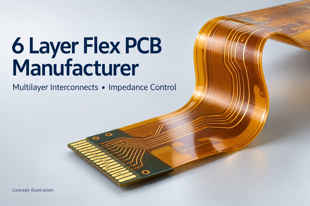
6 Layer Flex PCB Manufacturing Capabilities
BestFPC supports six-layer flexible circuit manufacturing with material, surface finish, and impedance requirements reviewed against the proposed construction. Our standard impedance tolerance capability is ±10%, subject to confirmation for the specific stackup and circuit geometry.
| Manufacturing Parameter | Available Scope |
|---|---|
| Layer Count | Six-layer flexible circuits |
| Base Construction | Adhesive-based or adhesiveless polyimide cores |
| Impedance Tolerance | ±10%, subject to stackup review |
| Surface Finish Options | ENIG, electroplated gold, OSP, tin plating |
| Local Reinforcement | PI or FR4 stiffeners, as specified |
These options describe the manufacturing scope, rather than a single combination that fits every design. Copper weight, dielectric thickness, bonding materials, and reinforcement must be selected together.
For an impedance-controlled order, specify the target value, tolerance, signal type, routing layer, and reference plane. A nominal impedance value alone does not define the required construction or acceptance test. BestFPC’s engineering review helps align these requirements with the fabrication drawings before the build is released.
6 Layer Flex PCB Stackup and Bend Requirements
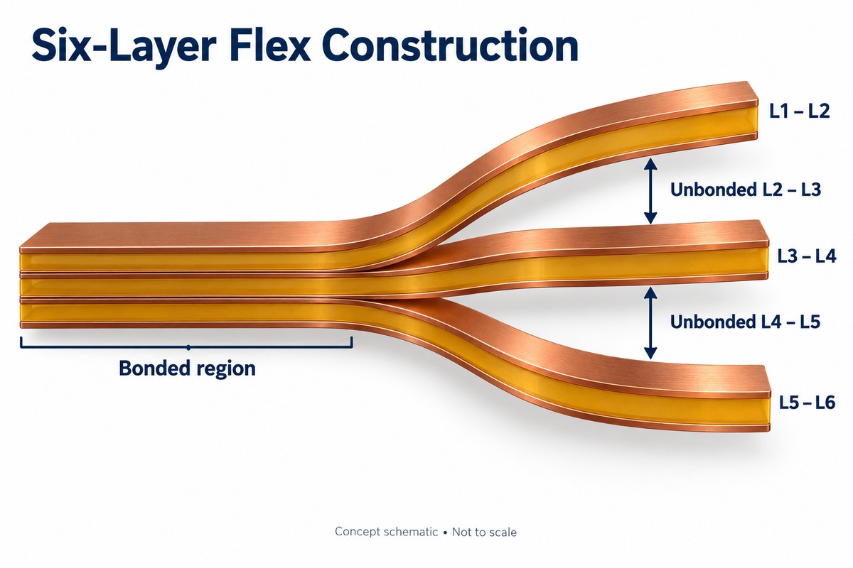
A six-layer flex PCB needs a stackup that supports both its electrical function and its installed shape. Bonding all layers together and leaving selected regions unbonded produce different mechanical behavior, so the bending area should be identified before the construction is finalized.
- Bonded regions: The layers form a consolidated multilayer structure. Identify where this construction is needed and whether those regions must bend during installation.
- Unbonded regions: Selected sections remain separated into thinner flexible groups. BestFPC’s multilayer offering includes this approach, and the six-layer example below uses three double-layer groups.
- Impedance geometry: Define the signal-to-reference relationship and dielectric separation for the relevant traces. Where layers separate, review whether the intended reference structure remains intact.
- Bending conditions: Specify the bend location, installed radius, direction, and whether movement occurs once during assembly or repeatedly in service.
A board that can fold into an enclosure is not automatically qualified for repeated motion. Dynamic applications need a construction and validation plan based on the actual movement, rather than a bend-radius assumption derived only from the total layer count.
For a quotation, a drawing showing the installed shape is especially useful. It lets the engineering discussion address the flexible section, nearby stiffeners, and interconnections as one assembly.
6 Layer Flex PCB vs. Rigid-Flex PCB
A six-layer flex PCB uses a flexible circuit construction, with local stiffeners where needed. A rigid-flex PCB integrates rigid circuit sections with flexible interconnections. The choice depends on whether the assembly needs a flexible circuit with reinforcement or integrated rigid areas for component mounting.
A 6 layer rigid-flex pcb manufacturer is relevant when your design calls for rigid mounting sections connected by flex regions within the same board assembly. BestFPC supports both product categories, so the structure should be established before comparing quotations.
| Design Feature | Six-Layer Flex PCB | Six-Layer Rigid-Flex PCB |
|---|---|---|
| Circuit Structure | Flexible multilayer construction | Integrated rigid and flexible regions |
| Local Support | Attached stiffeners | Rigid circuit sections |
| Layer Definition | Six conductive layers in the multilayer region | Layer count varies by region |
| Typical Procurement Need | Flexible interconnect with local reinforcement | Component-bearing rigid sections with flex links |
An FR4 stiffener adds mechanical support; it does not by itself turn a flexible circuit into a rigid-flex PCB. This distinction matters when specifying materials, construction drawings, and assembly requirements.
When requesting a quote from a 6 layer rigid flex pcb manufacturer, identify the rigid-region stackup and the number of conductive layers that continue through each flex region. A multilayer rigid flex PCB described as “six-layer” should not be assumed to contain six flexible layers throughout its entire outline.
DFM Review for Six-Layer Flexible Circuits
BestFPC reviews customer Gerber files and drawings before production, with proposed design or material changes agreed with the customer. For a six-layer flex project, the review should turn the electrical and mechanical requirements into a consistent set of manufacturing instructions.
The key review items are:
- Stackup and impedance: Check layer order, material callouts, copper weights, dielectric thicknesses, and the traces assigned to each impedance requirement. Resolve conflicting notes between the stackup and fabrication drawing.
- Interlayer connections: Define the layers connected by each via structure. Confirm that blind-via requirements are intentional and compatible with the proposed build, rather than adding them simply because the board has six layers.
- Bend and stiffener boundaries: Mark the intended bend regions and local reinforcement. Review nearby pads, vias, and component locations against the mechanical drawing.
- Coverlay and connection areas: Check pad openings, connector contact areas, and local thickness requirements so the finished circuit matches its mating interface.
- Acceptance requirements: Identify electrical tests, impedance verification, dimensional checks, and any application-specific bend testing required for approval.
This review gives purchasing and engineering a common basis for comparing revisions and quotations. Material substitutions or construction changes should be approved before production, especially when they affect impedance or the installed thickness.
Six-Layer Flex PCB Manufacturing Case Study
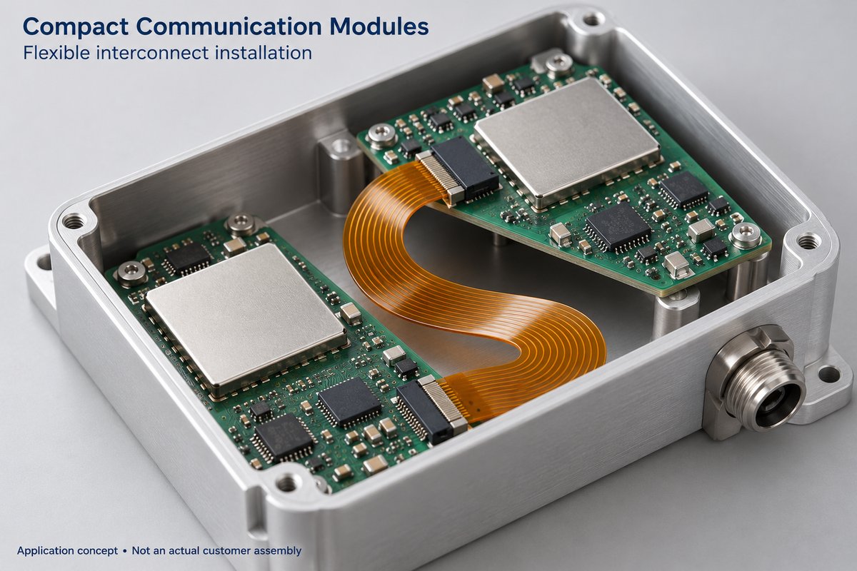
Application: Compact Communication Modules
BestFPC manufactured a six-layer flexible PCB featuring blind vias, three double-layer groups, and unbonded sections for compact multilayer interconnections. Its 50 Ω impedance specification and local FR4 reinforcement make this construction suitable for space-constrained communication modules requiring controlled signal routing and folded installation.
Manufacturing Challenges & Solutions
- Blind-Via Interconnection: Precise drilling and layer registration support reliable connections within the six-layer structure.
- Unbonded Layer Construction: Selective bonding preserves the separated regions between layers 2–3 and 4–5 for flexible installation.
- Impedance Control: Copper geometry, dielectric thickness, and reference layers are reviewed against the specified 50 Ω impedance.
- Mechanical Reinforcement: Local FR4 stiffeners provide additional support for designated connector or mounting areas.
Product Specifications
| Parameter | Specification |
|---|---|
| Layers | 6 |
| Construction | Three double-layer groups |
| Via Type | Blind vias |
| Unbonded Interfaces | L2–L3, L4–L5 |
| Board Thickness | 0.40 ± 0.05 mm |
| FR4 Stiffener | 0.48 mm |
| Copper Weight | 0.5 oz |
| Impedance | 50 Ω specified |
| Surface Finish | ENIG |
| Coverlay | 0.5 mil |
This project showcases BestFPC's experience with complex multilayer flexible circuits, combining blind-via interconnections, selective bonding, impedance requirements, and local reinforcement in one PCB construction.
Quality Control for 6 Layer Flex PCBs
BestFPC’s published quality process includes automated optical inspection, in-process checks, and 100% inspection and electrical testing before delivery. For a six-layer order, the inspection plan should also identify any additional checks needed to verify the agreed stackup and impedance requirements.
- Circuit inspection: AOI at relevant circuit-processing stages checks conductor patterns for defects before they become inaccessible within the laminated structure.
- In-process control: Checks during manufacturing help identify material or processing problems before the board reaches final inspection.
- Final electrical testing: Continuity and isolation testing checks for opens and shorts. It does not replace controlled-impedance verification.
- Project-specific verification: Agree on the impedance test method, acceptance tolerance, and required records before production. Repeated-bend testing also needs a defined motion profile and acceptance criteria when the application requires it.
For purchasing, the useful question is which requirement each inspection verifies. Request the reports needed for your approval process as part of the order specification, rather than assuming every available test is included automatically.
Why Choose BestFPC as Your 6 Layer Flex PCB Manufacturer?
BestFPC combines six-layer flex manufacturing with engineering review and impedance-control support. This is useful when your purchasing decision depends on whether the proposed circuit can meet both the electrical requirements and the assembly drawing.
- Relevant product experience: Our published six-layer example includes blind holes, unbonded interfaces, FR4 reinforcement, and a specified impedance. It provides a practical starting point for discussing comparable construction needs.
- Engineering coordination: Review of customer drawings and materials helps identify questions before production. Proposed changes are discussed with the customer rather than silently substituted.
- Defined quality checks: AOI, process inspection, and final electrical testing support fabrication quality, with additional acceptance requirements agreed for the project.
For a useful quotation, provide Gerber and drill files, the proposed stackup, impedance requirements, a mechanical drawing showing bends and stiffeners, and the required quantity. Include the BOM and assembly information if component assembly is also required.
State your target delivery date and required approval documents. These details help BestFPC assess the build and quotation without relying on assumptions about materials, inspection scope, or assembly conditions.
FAQs about 6 layer flex pcb manufacturer
What is the minimum thickness of a six-layer flex PCB?
There is no single minimum thickness for every six-layer construction. Copper, polyimide, bonding layers, and coverlay all contribute to the finished thickness. BestFPC’s product example above specifies 0.40 ±0.05 mm without the stiffener; it is not a universal minimum.
Can a six-layer flex PCB bend repeatedly?
Repeated bending requires a design and validation plan for the actual motion. Layer count alone does not establish flex life. Specify the bend radius, movement, cycle requirement, and operating conditions so the construction can be reviewed appropriately.
Does every six-layer flex PCB need blind vias?
No. Via selection depends on the required layer connections and routing needs. Define the interconnection requirements first, then assess whether through-holes or blind vias suit the construction.
Can BestFPC provide impedance-controlled six-layer flex PCBs?
Yes. BestFPC supports impedance-controlled flex manufacturing, with a standard tolerance capability of ±10% subject to stackup review. Specify the target impedance, signal configuration, tolerance, and verification requirements for the quotation.
How are price and lead time determined?
They depend on the approved construction, materials, via requirements, quantity, inspection scope, and any assembly work. Send the fabrication files and target schedule so BestFPC can quote against the actual project requirements.
BestFPC brings multilayer manufacturing, engineering review, and quality inspection together to help buyers define a suitable six-layer flex build. For your next project, send the fabrication package, quantity, and delivery target to sales@bestfpc.com for a quotation based on your design.


.png)
.png)
.png)
.png)

.png)