


 2026-10-16
 BEST
BESTSculptured flex circuits are worth considering when a PCB interconnection needs flexible routing and metal terminals built into the same conductor pattern. Their value comes from the connection they simplify—not simply from being thin or flexible.
The choice turns on three practical questions: how the terminals meet the PCB, where the circuit must bend, and whether eliminating separate connector parts justifies a more specialized circuit design.
If you are comparing FPC interconnection options, email your board layout or a simple connection sketch to sales@bestfpc.com to discuss your requirements with BestFPC.
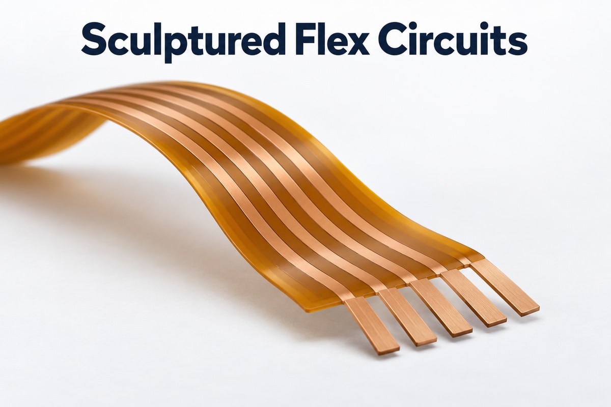
What Are Sculptured Flex Circuits?
Sculptured flex circuits use conductors with different copper thicknesses across the design. Thinner regions provide flexibility, while thicker terminal regions can form integral metal fingers extending beyond the insulating material.
Think of the structure in three parts:
- Flexible routing section: Carries the conductors between connection points and accommodates the intended installed shape.
- Thicker terminal section: Gives the exposed conductors more mechanical substance at the connection.
- Integral fingers: Continue from the circuit's conductor pattern rather than being separate pins attached to it.
These sculpted fingers are the defining feature to look for in a drawing. An unusual flex outline alone does not make a circuit sculptured. Suppliers also use the term sculpted flex circuits; the actual copper profile and terminal construction matter more than the label.
Variable copper thicknesses allow different regions to serve different purposes, but they do not make every part of the circuit equally flexible.
How Do Sculptured Flex Circuits Differ from Flex Circuits with Stiffeners?
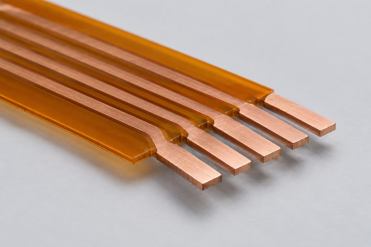
A stiffener supports the flex mechanically; a sculptured terminal changes the conductor itself. Adding a stiffener does not create a freestanding copper finger.
| Design feature | Sculptured construction | Flex with a stiffener |
|---|---|---|
| Local reinforcement | Thicker copper terminal | Added supporting material |
| Terminal structure | Integral exposed metal finger | Supported flex contact area |
| Main design purpose | Integrate the terminal | Stabilize a local area |
Choose a stiffener when the problem is support. For example, a flex tail may need a specified total thickness to fit its connector, or a component area may need reinforcement during assembly.
Consider sculptured construction when the terminal itself must change. A projecting conductor intended for direct PCB attachment solves a different problem from supporting a conventional flex tail.
Neither approach is a drop-in replacement for the other: the receiving interface must match the chosen construction.
When Can Sculptured Flex Circuits Replace Separate Connectors?
They can replace separate connector parts when integral terminals provide a suitable electrical and mechanical connection, particularly in fixed assemblies. They are less attractive when routine disconnection is central to the product's service plan.
- Limited connector space: Removing a connector housing may help packaging, provided the terminal route and soldering access still fit.
- Permanent board connections: Directly attached terminals may suit boards that remain connected throughout normal use.
- Repeated servicing: A detachable connector can make board replacement easier than desoldering integral fingers.
For example, replacing a ZIF connector with soldered fingers changes both assembly and servicing. It is a redesign of the interface, not simply a different flex tail inserted into the same connector.
Removing one component also does not remove every potential failure point. The remaining terminal joints and the way the flex is supported still determine how the connection behaves in use.
How to Choose Straight or Formed Contacts for PCB Connections?
Choose straight or formed contacts around the receiving PCB's position and attachment method. The terminal shape should reach the intended connection without forcing the flexible section or loading the solder joint.
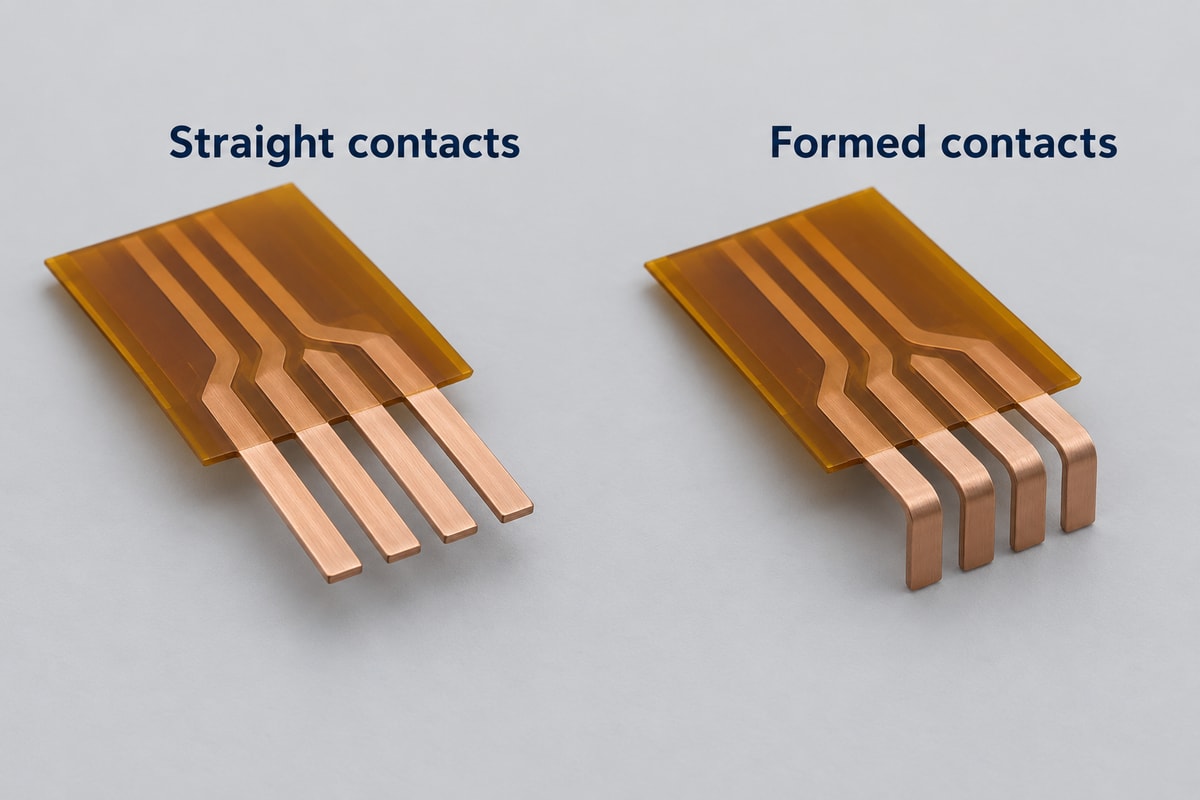
- Straight contacts: Consider these where the terminals can reach the receiving holes or pads directly. Straight does not automatically mean through-hole; the full geometry determines suitability.
- Formed contacts: Consider these where a deliberate change in terminal direction is needed. The formed height and angle become part of the assembly dimensions.
- Through-hole attachment: Match the terminal cross-section to the finished hole and provide suitable insertion clearance and soldering access.
- Surface attachment: Provide a defined overlap with the PCB pad and control terminal position and coplanarity during soldering.
Keep terminal forming separate from flex routing in the drawing. A formed metal finger establishes the contact geometry; bending the flexible section should not be used to compensate for an incorrectly positioned terminal.
How Do Finger Pitch and Length Affect PCB Assembly?
Pitch determines whether the terminal array aligns with the PCB pattern; length determines how the fingers reach and engage that pattern. Both must work across manufacturing tolerances, not just at nominal dimensions.
- Pitch and position: Use common reference dimensions for the finger array and receiving pads or holes. Specify positional tolerances as well as nominal spacing.
- Exposed length: Provide enough engagement for the chosen joint without unnecessary unsupported projection. Excess length can complicate handling or reduce clearance to nearby parts.
- Width and thickness: Check the complete terminal cross-section against the finished hole or pad geometry. Pitch alone cannot establish fit.
- Formed height: For surface attachment, terminal height variation can prevent consistent contact with the pads before soldering.
A useful prototype check is to assemble the circuit into the actual board spacing and enclosure. A finger array that aligns on a flat inspection surface may still be difficult to install once surrounding components restrict access.
Are Sculptured Flex Circuits Suitable for Repeated Bending?
Not automatically. A circuit that bends successfully during installation has not demonstrated that it can survive repeated movement.
The key is to keep the required motion compatible with the flexible region and away from vulnerable terminal transitions.
- Copper distribution: Thicker terminal copper provides local strength but also resists bending more than a thinner region of comparable geometry. For the flexible region, compare RA vs ED copper alongside the finished copper thickness and intended bending conditions.
- Bend location: Plan the moving section so motion does not concentrate at the exposed finger root, a solder joint, or an abrupt stiffness transition.
- Installed movement: Assess the bend path, available radius, travel and restraint together. A generous loose-loop shape can become a tight bend after the enclosure closes.
- Cycle validation: Test the intended construction under representative motion and environmental conditions, monitoring electrical continuity as well as visible damage.
For a repeatedly moving connection, compare a purpose-designed dynamic flex option before selecting sculptured terminals. The product name alone establishes no bend-radius or cycle-life rating.
When Are Sculptured Flex Circuits Worth the Additional Fabrication Complexity?
They are worth considering when the benefit of integrating the terminals outweighs the extra circuit fabrication, forming and assembly effort. Compare the complete installed connection rather than the bare flex price.
Separate the cost review into three parts:
- Parts removed: Count the connector components and associated purchasing or placement operations that the new design actually eliminates.
- Work added: Include special copper processing, terminal forming, handling fixtures and inspection where the design requires them.
- Lifetime consequences: Account for assembly yield and the cost of replacing a board connected by soldered terminals.
For an early prototype with an unsettled board layout, retaining a standard connector may make revisions easier. For a stable design with a clear packaging constraint, an integrated terminal can deserve closer evaluation.
There is no universal production quantity at which this construction becomes cheaper. Obtain comparable quotations for the same electrical function, assembly scope and quantity before treating connector elimination as a saving.
FAQs about sculptured flex circuits
Are sculptured flexible circuits the same as a rigid-flex PCB?
No. Sculptured construction describes the conductor thickness and integral terminal geometry. A rigid-flex PCB combines rigid and flexible circuit regions. The terms describe different structural features.
Are sculpted fingers always gold plated?
No single finish should be assumed from the name. The finish must suit the intended connection, such as soldering or mating contact, and be specified accordingly.
Does thicker terminal copper guarantee higher current capacity?
No. The thinner conductor sections, terminal joints and allowable temperature rise also limit the current path. Assess the complete circuit rather than the terminal thickness alone.
Can a standard FPC fabricator automatically manufacture this structure?
No. Ordinary flex fabrication capability does not establish the ability to produce the required copper profile, unsupported fingers or formed terminals. Confirm those specific features against the drawing.
For your next FPC interconnection project, send the board spacing, connection sketch and expected movement to sales@bestfpc.com. These details give BestFPC a starting point to discuss the design and establish which manufacturing requirements need further review.


.png)
.png)
.png)
.png)

.png)