


 2026-10-16
 BEST
BESTAn aerospace rigid-flex PCB may pass electrical testing yet develop failures under vibration, temperature changes, or mechanical stress. Copper cracks, weak plated holes, and poorly controlled rigid-to-flex transitions can compromise reliability after installation, making fabrication quality and material selection critical.
BestFPC provides custom aerospace rigid-flex PCB manufacturing and assembly services, supporting prototypes and volume production. Our free preliminary DFM review helps identify manufacturing risks before fabrication, reducing unnecessary revisions and clarifying project requirements.
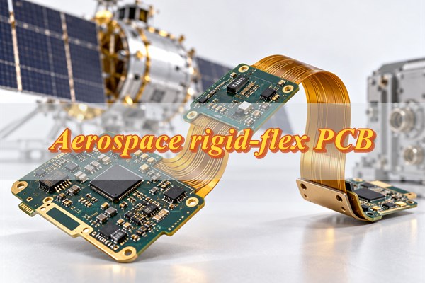
What Is an Aerospace Rigid-Flex PCB?
An aerospace rigid-flex PCB integrates rigid component-mounting sections and flexible interconnections into one circuit board. It is used in avionics, satellite electronics, UAV control systems, and navigation equipment where weight, space, and connection reliability matter.
Rigid-flex construction can replace selected cables and connectors, reducing wiring complexity and interconnection points. Its suitability depends on the application's bending, vibration, thermal, and electrical requirements.
What Makes Aerospace Rigid-Flex PCB Manufacturing Challenging?
The main manufacturing challenges involve rigid-to-flex transitions, material compatibility, bending reliability, and multilayer alignment. Poor control in these areas can cause electrical failures or mechanical damage during assembly and operation.
- Rigid-to-Flex Transitions: Changes in board stiffness can concentrate stress near transition areas, increasing the risk of copper cracking, insulation damage, or delamination.
- Material Compatibility: Polyimide, rigid laminates, copper, and bonding materials respond differently to temperature changes. Incompatible constructions can cause warpage or interlayer separation.
- Bending and Vibration: Repeated movement can fatigue copper conductors, while vibration may stress unsupported sections and mounted components. Bend radius and mechanical support must match operating conditions.
- Dimensional Stability: Material expansion and shrinkage during fabrication can affect layer registration, hole alignment, and the accuracy of rigid-to-flex transitions.
These risks become more significant in designs with tight mechanical tolerances, narrow bend regions, or complex multilayer structures.
How Are Aerospace Rigid-Flex PCBs Manufactured and Assembled?
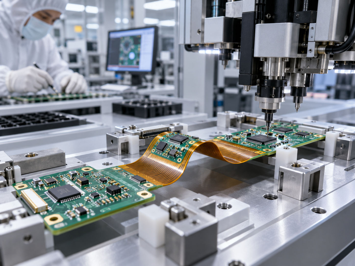
Aerospace rigid-flex PCB manufacturing combines flexible circuit fabrication, controlled lamination, reliable interconnections, and supported component assembly. Each stage follows the approved stackup and fabrication specifications.
Step 1: Flexible Circuit Fabrication
Polyimide copper-clad materials are patterned to form the flexible circuits. Copper dimensions, conductor spacing, and coverlay openings are processed according to the approved manufacturing data.
RA copper and adhesiveless constructions may be selected for demanding bending applications, depending on the stackup and mechanical requirements.
Step 2: Rigid-Flex Lamination
Flexible layers are integrated with rigid sections using specified dielectric and bonding materials. Lamination parameters are controlled to maintain alignment and prevent unwanted resin flow into designated flexible regions.
Step 3: Drilling, Plating, and Finishing
Holes and vias are formed and plated according to the layer structure. Outer-layer processing, solder mask application where specified, surface finishing, and profiling follow the approved fabrication drawings.
Plated-hole integrity and dielectric separation require careful control to maintain reliable electrical interconnections.
Step 4: PCB Assembly
SMT and through-hole components are mounted in designated assembly areas. Fixtures or carriers may support the board during solder paste printing, component placement, and soldering.
Flexible sections must be protected from unintended bending and handling damage. Stiffeners and mechanical support should match the approved assembly specifications.
Completed assemblies undergo the agreed inspections before delivery.
What Quality Standards Apply to Aerospace Rigid-Flex PCB Manufacturing?
Aerospace rigid-flex PCB manufacturing must meet applicable product specifications, acceptance criteria, and customer-defined quality requirements. Supplier quality certifications and individual PCB qualification serve different purposes.
| Standard | Scope | Buyer Consideration |
|---|---|---|
| AS9100D | Aerospace quality management | Supplier certification and scope |
| IPC-6013F | Flexible and rigid-flex PCB qualification and performance | Product class, acceptance criteria |
| IPC-2223F | Flexible and rigid-flex PCB design | Construction and bending requirements |
| IPC-A-600 | Bare PCB acceptability | Applicable inspection criteria |
| IPC J-STD-001 | Soldered assembly requirements | Assembly workmanship |
| IPC-A-610 | Electronic assembly acceptability | Assembly acceptance class |
| Customer Specifications | Project-specific requirements | Qualification, records, testing |
Confirm the required IPC class, standard revisions, and project-specific acceptance criteria before production. AS9100D applies to a supplier's quality management system; individual PCB qualification must follow the customer's approved requirements.
How Are Aerospace Rigid-Flex PCBs Inspected and Tested?
Aerospace rigid-flex PCB inspection verifies electrical continuity, dimensional accuracy, conductor integrity, and manufacturing quality. Additional reliability tests may be specified according to operating conditions and project requirements.
| Inspection / Test | Purpose | Typical Defect or Risk |
|---|---|---|
| Electrical Testing | Verify continuity and isolation | Open and short circuits |
| Visual / AOI Inspection | Examine circuit features | Etching defects, coverlay misalignment |
| Dimensional Inspection | Verify critical tolerances | Outline, hole, alignment deviations |
| Microsection Analysis | Examine internal structures | Plating defects, delamination |
| Bend Testing | Evaluate specified flexing conditions | Copper cracking, connection failure |
| Thermal Stress Testing | Assess thermal exposure response | Interconnection or laminate degradation |
| Impedance Testing | Verify controlled-impedance structures | Impedance outside specified limits |
Electrical testing alone cannot establish long-term bending or thermal reliability. These properties require mechanical or environmental evaluation under defined conditions.
For aerospace orders, specify inspection methods, sampling quantities, acceptance limits, and required reports before manufacturing. Specialized environmental testing and aerospace product qualification are project-specific rather than automatically included in standard PCB fabrication.

What Affects Aerospace Rigid-Flex PCB Cost and Lead Time?
Materials, layer configuration, manufacturing tolerances, specialized processes, and testing requirements directly affect aerospace rigid-flex PCB cost and delivery schedules.
| Factor | Cost / Lead-Time Impact | Buyer Recommendation |
|---|---|---|
| Polyimide Materials | Material price and availability | Confirm material grade |
| Layer Configuration | Lamination and processing complexity | Finalize the stackup |
| Fine-Line Features | Fabrication difficulty and yield | Specify necessary tolerances |
| Blind / Buried Vias | Additional processing stages | Confirm interconnect requirements |
| Rigid-to-Flex Transitions | Construction and tooling complexity | Provide bend and transition drawings |
| Surface Finish | Material and processing requirements | Match assembly conditions |
| Reliability Testing | Testing time and documentation | Define the required test scope |
| PCB Assembly | Component sourcing and assembly operations | Submit complete assembly files |
| Order Quantity | Setup and production planning | Provide sample and production forecasts |
Late material changes, incomplete bending specifications, and undefined testing requirements can increase costs or delay production. Confirming the stackup, material availability, and inspection scope during the initial manufacturing review helps establish a more accurate quotation.
Why Choose BestFPC for Aerospace Rigid-Flex PCB Manufacturing?
BestFPC provides in-house rigid-flex PCB fabrication and SMT assembly, helping customers reduce supplier handoffs and manage prototype and volume production orders through one manufacturing partner.
- Free DFM Review Before Production: Check bend radius, rigid-to-flex transitions, via placement, coverlay openings, and stackup feasibility before committing to fabrication.
- Custom Rigid-Flex Manufacturing: Access multilayer rigid-flex fabrication, polyimide materials, RA/ED copper, controlled impedance, and blind/buried via options to meet your specifications.
- Fast Prototyping and Volume Production: Request quick-turn prototypes and scale to larger orders without changing your PCB manufacturing supplier. Lead times are confirmed based on complexity and material availability.
- In-House PCB Fabrication and SMT Assembly: Reduce supplier handoffs, separate shipping arrangements, and communication delays by combining PCB manufacturing and component assembly.
- Flexible Component Sourcing: Choose full turnkey, partial turnkey, or consigned assembly according to your BOM, approved suppliers, and purchasing requirements, subject to project confirmation.
- Quality Inspection and Documentation: Specify IPC-6013 Class 2 or Class 3 requirements, electrical testing, inspection reports, and production records according to your project's acceptance criteria.
BestFPC provides DFM technical guidance for customer-supplied designs, not original circuit design or aerospace product qualification. Special inspection, certification, and documentation requirements are reviewed according to the project's manufacturing scope.
What Information Is Required for an Aerospace Rigid-Flex PCB Quote?
Provide your PCB design files, stackup, bending specifications, quality requirements, and order quantity for an accurate quotation.
- PCB Files: Gerber or ODB++, drill files, and fabrication drawings.
- Stackup & Materials: Layer structure, material types, copper thickness, and surface finish.
- Bending & Manufacturing: Bend radius, flex locations, critical tolerances, and impedance requirements.
- Quality Requirements: IPC class, inspection criteria, and required test reports.
- Order & Assembly: Quantity, delivery requirements, and BOM and assembly files if applicable.
Send your files to sales@bestfpc.com for a free preliminary DFM review and quotation.
FAQs About Aerospace Rigid-Flex PCBs
Q1: Can aerospace rigid-flex PCBs withstand repeated bending?
A1: Yes, when designed for dynamic flexing. Bend radius, copper type, flex-layer thickness, and expected cycles determine durability. Installation-bend circuits should not automatically be used for repeated movement.
Q2: Can rigid-flex PCBs replace wire harnesses in aircraft electronics?
A2: Yes, in suitable applications. Rigid-flex construction can reduce cables and connectors, but mechanical fit, maintainability, and qualification requirements must be evaluated before replacement.
Q3: Can components be mounted on both sides of a rigid-flex PCB?
A3: Yes. Components are generally mounted on rigid or reinforced sections. Solder joints and component bodies must be protected from bending stress during assembly and installation.
Q4: Can aerospace rigid-flex PCBs support high-speed signals?
A4: Yes. Controlled impedance, dielectric properties, reference planes, and transition geometry affect signal integrity. Performance should be verified against the required operating conditions.
Q5: Can rigid and flexible sections use different copper thicknesses?
A5: Yes, depending on the construction. Copper thickness influences current capacity, flexibility, and manufacturing requirements, so the complete stackup must be reviewed.
Q6: Is polyimide suitable for high-temperature aerospace applications?
A6: Polyimide offers good thermal stability, but adhesives, coverlay, copper, and rigid materials must also meet the specified operating and processing temperatures.
Q7: Can aerospace rigid-flex PCBs incorporate blind and buried vias?
A7: Yes. Feasibility depends on layer connections, via geometry, manufacturing tolerances, and reliability requirements. Via placement near bending regions requires particular attention.
Q8: Do satellite rigid-flex PCBs require additional qualification?
A8: They may. Outgassing, thermal-vacuum, vibration, radiation, and mission-specific requirements depend on the satellite program and are separate from routine PCB fabrication.
Q9: Can customer-supplied materials be used for rigid-flex PCB manufacturing?
A9: Potentially, subject to process approval. Material specifications, certificates, condition, and manufacturing compatibility must be reviewed before accepting consigned materials.
Q10: Should aerospace rigid-flex PCBs be bent before or after component assembly?
A10: The sequence depends on the approved assembly process. Controlled forming and suitable mechanical support help protect solder joints, components, and rigid-to-flex transitions.
Conclusion
Aerospace rigid-flex PCB manufacturing depends on suitable materials, controlled rigid-to-flex transitions, reliable interconnections, and clearly defined quality requirements. Confirming these specifications before fabrication helps reduce manufacturing risks, unnecessary revisions, and production delays.
Ready to manufacture your aerospace rigid-flex PCB? BestFPC provides custom rigid-flex PCB fabrication, assembly, prototypes, and volume production. Send your Gerber files, stackup, bending requirements, and order quantity to sales@bestfpc.com for a free preliminary DFM review and quotation.


.png)
.png)
.png)
.png)

.png)