


 2026-10-28

 BEST
A flexible PCB coil places a patterned copper winding on a thin insulating substrate, allowing the conductor to follow a defined footprint without the height of a conventional wound assembly. A successful build depends on matching the electrical design to copper thickness, trace geometry, layer connections and the final installation.
At BestFPC, we manufacture custom flexible circuits in China for customers worldwide. With ISO 9001, ISO 13485, IATF 16949 and AS9100D certifications, we bring structured quality management to demanding projects. Our free DFM review, in-house FPC manufacturing, PCBA support and no MOQ help you move from coil artwork to engineering samples and production. Send your drawings to sales@bestfpc.com for a manufacturing review and quotation.
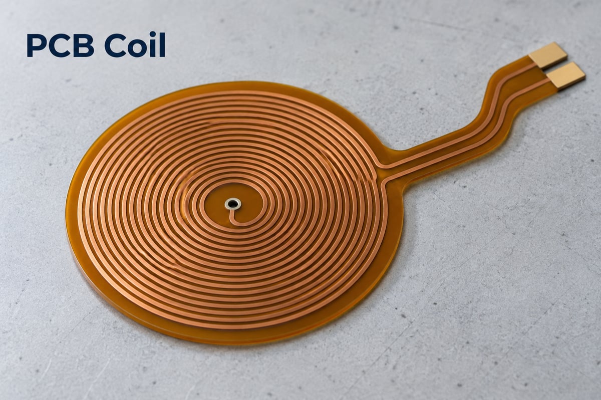
What Is a PCB Coil?
A PCB coil is a winding formed by copper traces on a circuit board rather than by winding insulated wire. Its conductor follows a continuous path, often arranged as a planar spiral, with terminals that connect it to the surrounding circuit.
A flexible version uses a substrate such as polyimide to accommodate thin, shaped assemblies. The coil area can remain flat while a connecting tail bends toward another board. Flexibility alone does not establish suitability for continuous movement; the bend region needs its own structural assessment.
The term PCB inductor can describe a printed winding, while an inductor on PCB may simply mean a separate component soldered to a board. For a manufacturing enquiry, identify whether you need the printed coil itself, a populated assembly or both.
Coil on PCB or Wire-Wound Coil for Your Application?
Choose a coil on PCB when controlled planar geometry, low installation height or integration with a flexible tail is a primary requirement. Consider a wire-wound construction when the design needs a conductor cross-section, magnetic core arrangement or three-dimensional winding that is difficult to accommodate in etched copper.
| Project requirement | Selection consideration |
|---|---|
| Thin, shaped installation | A flex coil can follow the available footprint |
| Integrated connection tail | Combine winding and interconnect in one circuit |
| High current or low winding resistance | Compare copper losses with a wire-wound alternative |
| Inductive sensing | Match geometry to the target and sensing distance |
| Wireless power transfer | Evaluate coupling, losses, alignment and temperature |
For a PCB coil for wireless charging, fitting the available space is only one requirement. The coil must also work with the drive circuit, receiver, magnetic materials and enclosure. A thin printed structure should not be selected solely because it is easier to package.
A planar PCB coil used for sensing has a different design task from a power-transfer winding. Nearby metal and other conductors can change its response, so sample evaluation should reproduce the intended installation. TI’s inductive-sensor design guidance explains these application-dependent effects.
Custom Flex PCB Coil Manufacturing
BestFPC manufactures flexible coil circuits to customer artwork, with material, protective layers, outline and connection features selected around the assembly. Our role is to turn an agreed electrical layout into a producible flex circuit and identify fabrication constraints before tooling and production.
| Pure FPC capability | Available range or option |
|---|---|
| Layer count | 1–4 layers |
| Finished thickness | 0.06–0.60 mm |
| Core construction | Adhesive or adhesiveless |
| Adhesiveless core copper options | 0.33, 0.5, 1 or 2 oz |
| Adhesiveless core PI options | 0.5, 1, 2 or 3 mil |
These are general FPC options, not a promise that every combination is suitable for a dense coil. The finished stackup includes the selected copper, insulation and protective layers; base-copper weight must not be confused with finished conductor thickness.
For a thin assembly, an adhesiveless core removes the bonding adhesive between the base copper and PI. Coverlay or solder mask protects the specified circuit areas, while openings leave connection pads accessible. A flat PCB coil may also need local stiffening at its terminals even when the winding region must remain thin.
Where the project includes components or soldered connections, our FPC manufacturing and PCBA support allow fabrication and assembly requirements to be considered together. Pad access, local support and handling need to be established before the flex circuit reaches assembly.
PCB Coil Design for Manufacturable Trace Geometry
A manufacturable PCB coil design must fit the required turns within the available area while preserving producible conductor widths and gaps at the selected copper thickness. Our free DFM review checks these dimensions together, rather than approving each parameter in isolation.
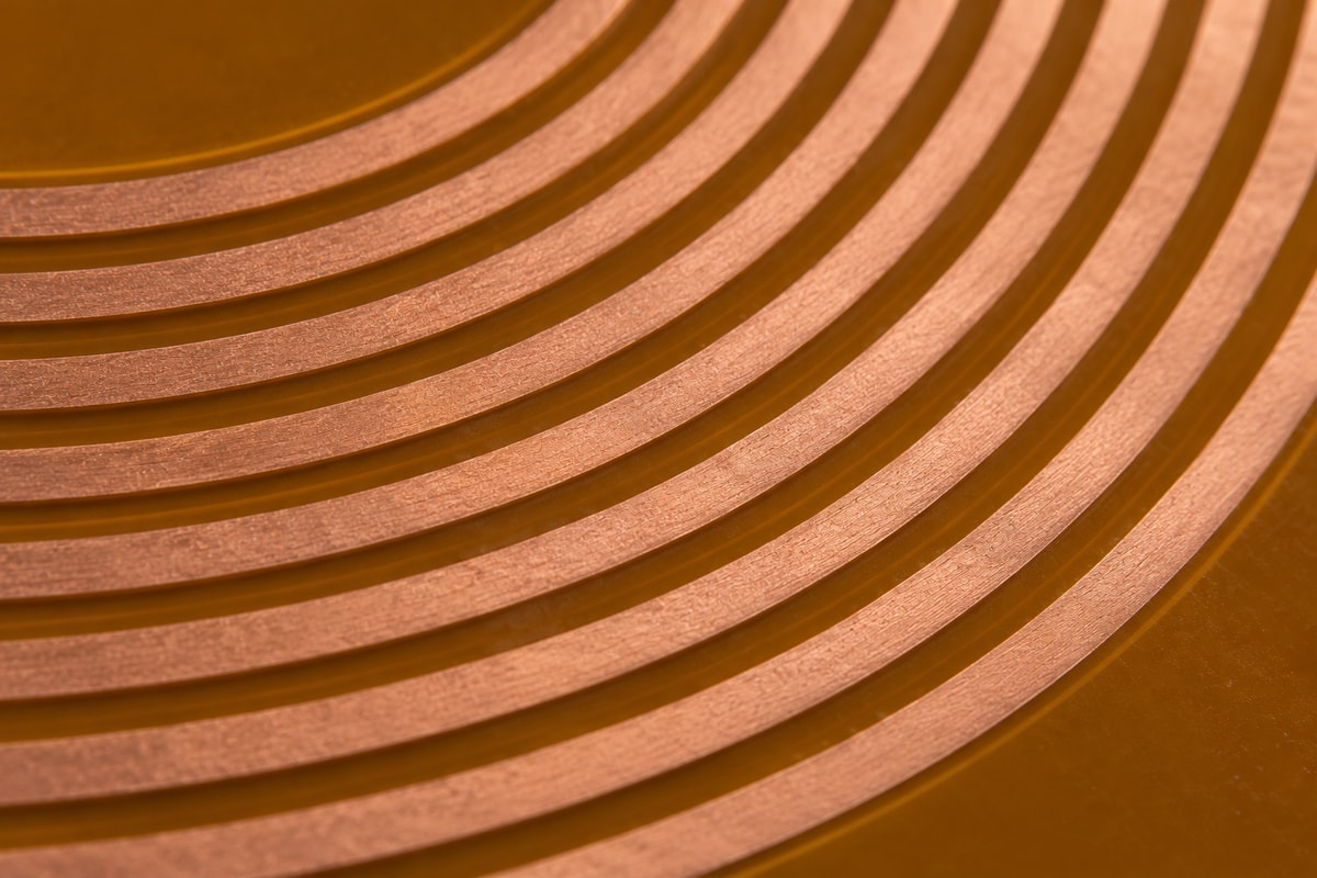
- Copper thickness and spacing: Thicker copper can reduce DC resistance, but it also changes the etching conditions needed to maintain a narrow gap. Increasing copper thickness may require a revised spacing or footprint.
- Turns and conductor length: Adding turns lengthens the current path and can increase resistance. It also changes inductance and parasitic capacitance, so more turns do not automatically improve performance.
- Finished geometry: State whether dimensions refer to copper edges or centerlines. Define the finished trace width and gap separately from any production artwork compensation.
Our general FPC design rules list 3/3 mil inner-layer and 3.5/3.5 mil outer-layer width/space before compensation for 18 μm finished copper. These are reference conditions for engineering review. A long, densely repeated coil pattern needs a layout-specific assessment; the general minimum is not an automatic coil acceptance limit.
For a uniform conductor, the first-order DC resistance relationship is R = ρℓ/(wt), where ℓ is conductor length, w is width, t is copper thickness and ρ is copper resistivity at the relevant temperature. It explains why widening a trace can reduce resistance but also consume space otherwise available for turns.
Use the actual routed length for the final estimate, including terminal connections and vias where relevant. DC resistance alone does not establish AC loss or temperature rise. We identify the manufacturing trade-offs; changes to turn count or winding geometry need the electrical designer’s approval.
Multilayer PCB Coil Stackups and Terminal Connections
A multilayer PCB coil needs a defined current path through every layer, with winding direction, interlayer connections and terminal positions shown in the fabrication data. Layer count by itself does not establish the resulting inductance or current capability.
Series windings require the layer connections and current direction to produce the intended magnetic relationship. Parallel windings require attention to resistance differences and current sharing. In either arrangement, dielectric spacing affects coupling and parasitic capacitance, so it belongs in the approved stackup.
The center terminal of a spiral also needs a practical escape route. A via and a trace on another layer can provide that route, but the via connection must be included in the electrical and mechanical design. Keep vias and abrupt stiffness transitions out of regions expected to bend repeatedly.
At the assembly end, define pad geometry, surface finish, stiffener location and the method of connection. For a connector tail, confirm the connector drawing and required insertion thickness. For soldered terminals, provide enough supported area for assembly without extending unnecessary stiffness into the flexible section.
BestFPC’s stackup and connection review brings these requirements into one fabrication package, reducing the risk of a mechanically suitable board arriving with an incompatible terminal structure.
PCB Coil Inspection and Electrical Acceptance
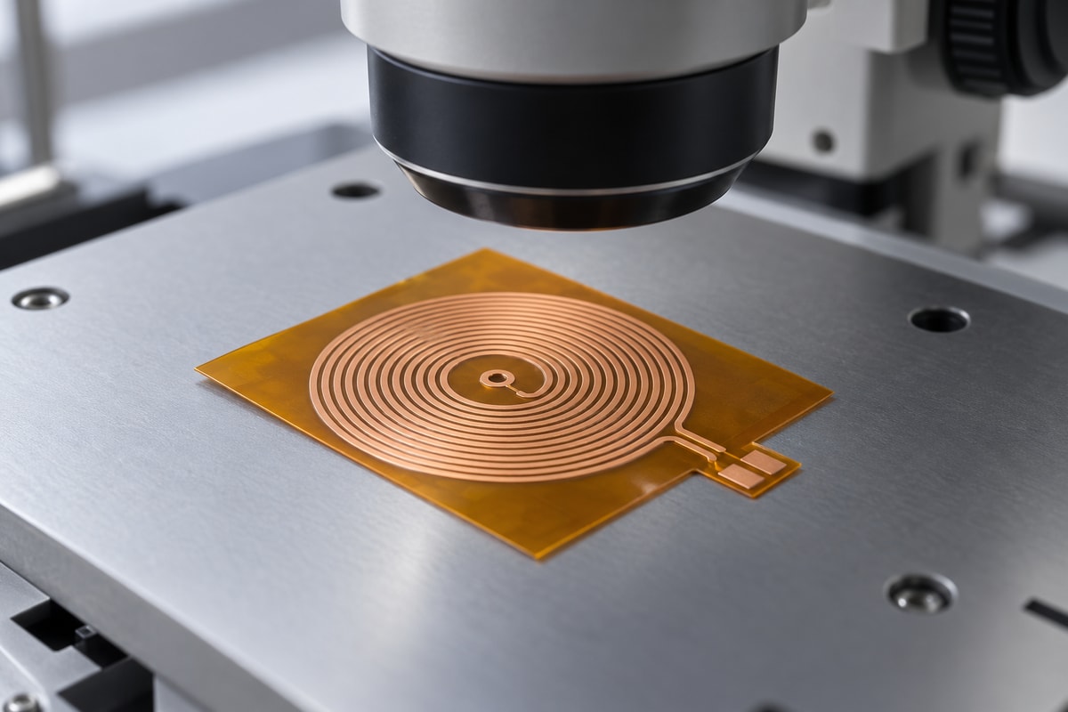
A PCB coil should be accepted against both its fabricated geometry and the electrical requirements agreed for the project. A continuity pass establishes a connected path; it does not prove that every turn remains electrically intact or that the coil meets its inductance target.
Our FPC quality-control process includes optical inspection, in-process checks and electrical testing. For coil artwork, the inspection plan must address bridges between adjacent turns of the same network, which a conventional netlist open/short test may not identify.
| Check | Acceptance basis |
|---|---|
| Trace width, gaps and outline | Approved drawing and tolerances |
| Missing copper or turn-to-turn bridges | Optical comparison with coil artwork |
| Opens and shorts between separate networks | Approved electrical connectivity |
| Cover openings and terminal features | Fabrication and assembly drawings |
| DCR | Agreed limits, temperature and contact method |
| Inductance and Q | Agreed frequency, fixture and measurement model |
Specify electrical acceptance conditions before ordering samples. For low-resistance coils, lead and contact resistance may materially affect a two-wire reading; a four-wire method may be appropriate. Inductance and Q also require a stated measurement frequency and fixture arrangement.
Project-specific DCR, inductance and Q testing must be agreed separately from standard bare-board electrical testing. Final sensing response, charging efficiency and operating temperature belong to validation of the assembled product in its actual environment.
POS Terminal Application Case Using a Two-Layer Flex PCB Coil
Our two-layer flexible coil board is suitable for a thin circuit installation within a POS terminal. It contains only two coil traces, making continuity and separation of those paths central manufacturing requirements. The construction combines a thin PI substrate, protected circuit areas and adhesive for attachment within the assembly.
- Two continuous circuit paths: An open or unintended short can disrupt the circuit. The manufacturing priority is preserving the complete artwork and checking both trace integrity and separation.
- Protected and solderable areas: The white solder mask protects designated non-soldering regions, while ENIG provides a solderable finish on exposed connection areas.
- Thin, attachable construction: The adhesiveless flex structure and 3M 468 adhesive support a low-profile mounting arrangement. Adhesive coverage and connection access must follow the assembly drawing.
| Product feature | Specification |
|---|---|
| Circuit construction | Two-layer flex |
| PI thickness | 18 μm |
| Core construction | Adhesiveless |
| Surface finish | ENIG |
| Coil circuit | Two traces |
| Circuit protection | White solder mask |
| Silkscreen | White and black |
| Adhesive | 3M 468 |
Why Choose BestFPC for Coil PCB Manufacturing?
Choose BestFPC when you need a manufacturing partner who can connect flexible-circuit fabrication with the engineering and assembly decisions around it. Our advantage is direct coordination between FPC production, engineering, quality and project support, with a clear path from development samples to repeat orders.
- In-house FPC manufacturing and PCBA support: Fabrication and assembly questions can be resolved together, reducing the number of separate suppliers you need to coordinate for a combined project.
- Experienced technical and production leadership: Our engineering, production, quality and business leaders each have more than ten years of relevant experience. This supports practical discussions about drawing changes, manufacturing constraints and production priorities.
- Experience with demanding customer requirements: Our work with medical-brand customers reinforces the need for clear specifications, quality documentation and coordinated responses to project changes.
- Support beyond the first sample: We can discuss prototype, small-batch and production requirements within the same manufacturing relationship, so the design review includes the intended route to repeat supply.
For qualification, specify the quality records, material requirements and change-notification expectations your purchasing team needs. Agreeing these requirements before supplier approval gives both teams a concrete basis for future orders.
PCB Coil Prototypes, Pricing and No MOQ Orders
BestFPC supports PCB coil projects without a minimum order quantity, allowing you to purchase engineering samples or a small validation batch before committing to production. No MOQ removes a quantity threshold; tooling, engineering setup and any agreed special testing can still affect the order cost.
The main price drivers are circuit size and panel use, material availability, layer count, copper thickness, dense winding geometry, connection features and assembly scope. A very small coil is not necessarily inexpensive if its geometry or test requirements make fabrication difficult.
For a useful quotation, send:
- Fabrication files: Gerber or equivalent artwork, outline and drill data.
- Construction requirements: Stackup, materials, copper and finished thickness.
- Acceptance requirements: Critical dimensions and any electrical test specification.
- Order details: Sample and production quantities, assembly scope and target date.
We establish lead time around the reviewed construction, material availability, tooling and testing requirements. If you expect design iterations, identify the quantities and decision dates for each build so sample approval can be coordinated with later production.
FAQs about PCB Coil
Can you quote a PCB coil from an inductance target alone?
An inductance target can start a discussion, but it is not enough for a firm manufacturing quote. We also need the available footprint, construction and fabrication data. If the winding has not been designed, identify who will complete the electrical design before requesting production.
Can I submit results from a PCB coil calculator for a manufacturing review?
Yes. Include the inputs and assumptions, together with the proposed artwork and stackup. A PCB coil inductance calculator provides a design estimate, not a manufacturing file. For a multilayer PCB coil calculator, also identify the winding connections and layer spacing used in the model.
Can a PCB coil replace a discrete inductor in my circuit?
Sometimes, but matching nominal inductance is insufficient. The designer must also evaluate current, loss, frequency response, self-resonance and the surrounding circuit. Manufacturing review follows once the proposed printed structure meets those electrical requirements.
Can alternative materials be used for repeat orders?
They can be considered, but substitution should follow approval rather than availability alone. Changes in dielectric thickness, copper construction or adhesive can alter the geometry, mechanical behavior or electrical response. Identify controlled materials and permitted alternatives in the drawing package.
Who verifies coil performance in the final assembled device?
The product owner or designated test partner verifies system-level performance. BestFPC supplies the agreed fabrication and assembly scope, with project-specific testing defined in the order. If you need an assembled test service, provide the procedure, fixture requirements and pass/fail limits for review.
Send your coil drawings and order requirements to sales@bestfpc.com. BestFPC offers free DFM, no MOQ, custom FPC manufacturing and assembly support to help you move from a proposed layout to a quoted, manufacturable build.


.png)
.png)
.png)
.png)

.png)