


 2026-10-28

 BEST
A bookbinder rigid-flex PCB allows multiple flexible circuit layers to fold into a compact space without placing excessive stress on the inner and outer layers. Its staggered flex lengths accommodate different bending paths, helping prevent copper stretching, buckling, and damage during installation.
However, incorrect length compensation, poor layer separation, or an unsuitable bend radius can still lead to failure. BestFPC provides custom rigid-flex PCB manufacturing, prototyping, and free DFM reviews, helping engineers identify manufacturing risks and evaluate complex stackups before production.
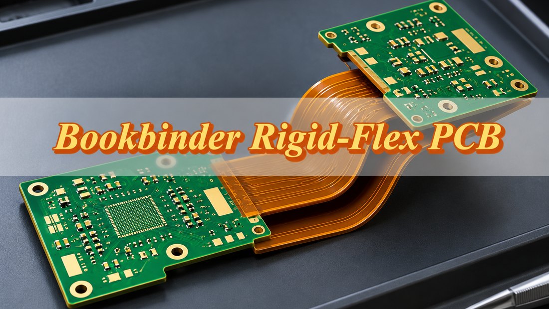
What Is a Bookbinder Rigid-Flex PCB?
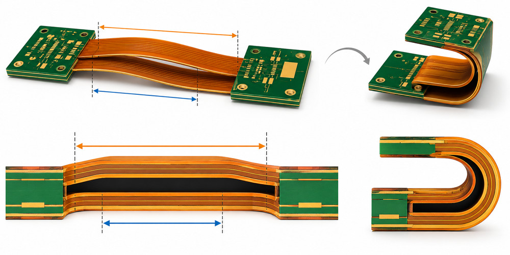
A bookbinder rigid-flex PCB is a multilayer rigid-flex circuit with separated flexible layers or sub-stacks of different lengths. The inner flex layer follows the shortest bending path, while each outer layer is progressively longer to accommodate its larger bending radius.
The construction resembles the pages of a book folding around its spine. Each flexible layer follows its own path instead of bending as part of one thick, fully bonded structure.
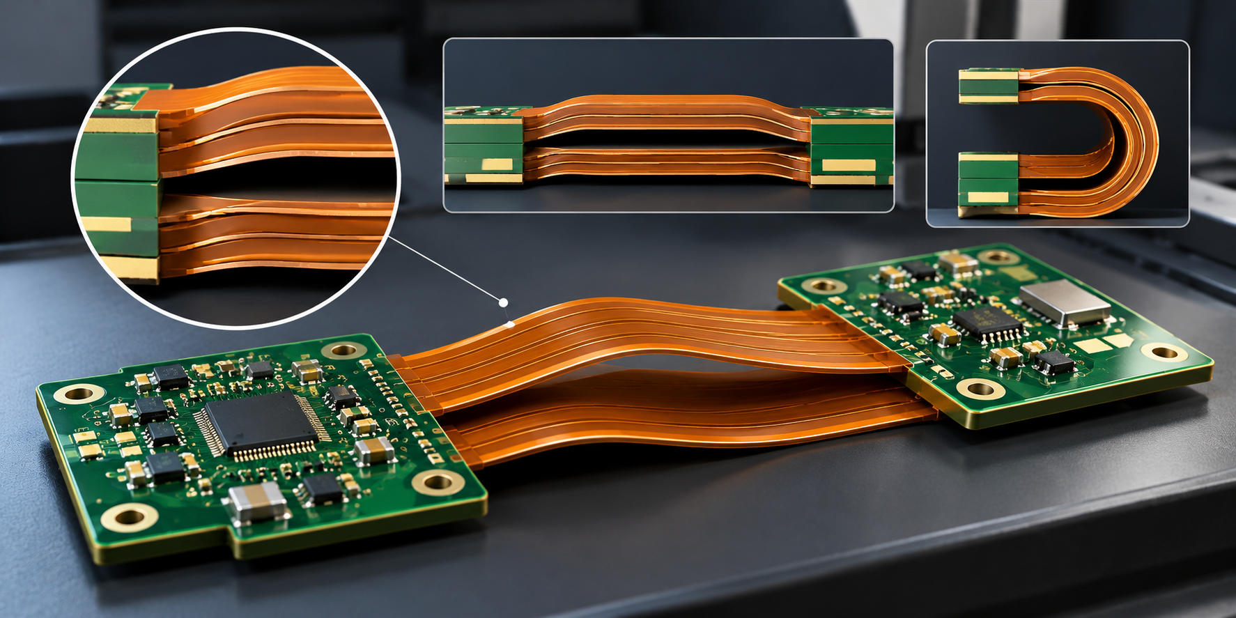
When the PCB is flat, the additional length may create a raised profile in the flexible section. Once folded, the layers should fit into their intended positions without excessive stretching, compression, or interference.
Bookbinder construction is particularly suitable for multilayer rigid-flex PCBs requiring compact installation folds, where conventional bonded or equal-length flex structures may experience excessive bending stress.
Bookbinder vs. Loose-Leaf vs. Bonded Rigid-Flex PCB: What Are the Differences?
Bookbinder construction uses separated flexible layers with calculated length compensation. Loose-leaf construction also separates the flex layers but does not necessarily include staggered lengths, while bonded construction keeps the flexible layers joined throughout the bending region.
| Feature | Bookbinder Rigid-Flex PCB | Loose-Leaf Rigid-Flex PCB | Bonded Rigid-Flex PCB |
|---|---|---|---|
| Flex construction | Separated sub-stacks with staggered lengths | Separated flexible sub-stacks | Flex layers bonded together |
| Length compensation | Calculated for different bending paths | Not necessarily included | No independent leaf-length compensation |
| Bending behavior | Accommodates inner and outer bending paths | Reduces combined bending stiffness | Layers bend as one thicker structure |
| Main advantage | Reduces tension and buckling in compact folds | Allows more independent flex movement | Simpler integrated construction |
| Main limitation | Requires precise offsets and specialized processing | Equal-length leaves may interfere in tight folds | Higher stiffness in thick multilayer flex sections |
| Suitable applications | Dense multilayer circuits with restricted folding space | Multilayer connections with sufficient bend clearance | Less demanding static bends |
Bookbinder is therefore a specialized form of loose-leaf construction rather than a completely separate technology.
When Should You Use Bookbinder Rigid-Flex Construction?
Bookbinder rigid-flex construction is most useful when multiple flexible layers must fold through a restricted space and equal-length layers would create excessive tension or compression.
It is particularly suitable for:
-
High-Density Multilayer Interconnections: Several signal, power, or reference-plane layers must connect rigid PCB sections without reducing routing capacity.
-
Compact 90° or 180° Installation Folds: Rigid sections occupy fixed positions inside an enclosure, leaving limited space for the flexible connection.
-
Aerospace Electronics: Compact avionics, navigation modules, and control assemblies require multilayer connections with controlled bending geometry.
-
Medical and Industrial Equipment: Diagnostic instruments, industrial controllers, and high-density modules need reliable folded connections between rigid sections.
Not every multilayer rigid-flex design needs bookbinder construction. A thinner flex stackup, longer connection, or simpler loose-leaf arrangement may meet the same mechanical requirements.
Bookbinder construction is generally intended for a defined folding direction. Applications involving continuous movement, reverse bending, or twisting need additional fatigue evaluation rather than relying on the bookbinder structure alone.
How Should You Design a Bookbinder Rigid-Flex PCB Stackup?
A bookbinder rigid-flex PCB stackup must account for flex layer separation, material thickness, length compensation, and the final folded configuration. The key design requirements include:
-
Layer Arrangement: Divide the flexible layers into separate sub-stacks. For example, an 8-layer rigid-flex PCB may use two independent 2-layer flex sub-stacks, with four additional copper layers confined to the rigid sections. The arrangement must support the required electrical connections and bending geometry.
-
Flex Materials and Thickness: Select polyimide laminates, copper foils, and coverlay based on the required flexibility. Adhesiveless polyimide and rolled-annealed (RA) copper may be suitable for demanding bending applications. Keep each flex sub-stack thin enough to meet its specified bend radius.
-
Layer Separation: Define the unbonded regions and air gaps between flex sub-stacks. Ensure adjacent layers can move without interference, and prevent bonding materials from entering areas intended to remain separated.
-
Length Compensation and Bend Radius: Specify the bend angle, folding direction, individual flex lengths, and minimum bend radius. Outer flex layers require additional length to accommodate their larger bending paths. Verify the geometry against the final folded assembly.
-
Rigid-to-Flex Transitions: Keep vias, solder joints, and abrupt conductor changes away from active bending areas. Control coverlay terminations and rigid laminate edges to reduce stress concentration.
-
Circuit Routing and Impedance: Route conductors across the bend without sharp corners or unnecessary copper accumulation. For controlled-impedance circuits, account for the actual dielectric thickness, reference planes, and separation between flex sub-stacks.
Provide both flat stackup drawings and the final folded configuration so the manufacturer can verify layer alignment, bending clearance, and manufacturability before production.
How Do You Calculate Flex Layer Length Compensation and Bend Radius?
Bookbinder flex layer length compensation depends on the bend angle and the distance between adjacent flexible bending paths. The outer layers require additional length because they follow larger radii around the same bend.
For an ideal concentric bend, the additional length can be estimated using:
ΔL = (π × θ / 180) × H
Where:
-
ΔL: Additional outer flex length, in mm.
-
θ: Bend angle, in degrees.
-
H: Centerline-to-centerline distance between adjacent flex bending paths, in mm.
Consider a bookbinder rigid-flex PCB with two separated flex sub-stacks:
-
Bend angle: 180°
-
Inner flex centerline radius: 2.0 mm
-
Centerline distance between sub-stacks: 0.20 mm
-
Straight flex length: 4.0 mm on each side of the bend
The inner flex path length is:
L(inner) = 4 + π × 2.0 + 4 = 14.28 mm
The outer flex path follows a larger centerline radius of 2.20 mm:
L(outer) = 4 + π × 2.20 + 4 = 14.91 mm
The additional length is:
ΔL = 14.91 − 14.28 = 0.63 mm
The outer flex sub-stack therefore needs approximately 0.63 mm of additional developed length for this idealized 180° bend. With the same centerline spacing, a 90° bend would require approximately 0.31 mm of extra curved-path length.
These calculations assume concentric bending paths and equal straight-section lengths. Actual manufacturing dimensions must also consider flex thickness, neutral-axis positions, rigid attachment geometry, material deformation, and tolerances.
Length compensation and minimum bend radius are separate design requirements. The correct length difference allows the flex layers to follow their intended paths, but each sub-stack must still have a suitable bend radius for its finished thickness, copper construction, and expected movement.
For three or more flex sub-stacks, calculate each layer's length using its own bending centerline. The final folded geometry should be checked for wrinkles, layer interference, and excessive tension before fabrication approval.
How Are Bookbinder Rigid-Flex PCBs Manufactured?
Bookbinder rigid-flex PCB manufacturing requires accurate flex layer fabrication, controlled lamination, and precise length compensation. The main challenge is preserving the staggered lengths and separation of the flexible layers throughout production.
The typical manufacturing process includes:
-
DFM Review and Process Planning: Review the stackup, flex layer lengths, bend geometry, material specifications, and rigid-to-flex transitions. Determine the lamination sequence and tooling requirements.
-
Flexible Sub-Stack Fabrication: Image and etch the copper circuits, apply coverlay, and prepare each flex sub-stack to its specified developed length. The outer leaves include the required length compensation.
-
Layer Registration and Lamination: Align the flexible sub-stacks with the rigid laminates and bonding materials. Control temperature, pressure, and resin flow to prevent unintended bonding in the separated flex regions.
-
Drilling, Plating, and Circuit Processing: Complete the required interconnections and outer-layer circuitry. Use suitable tooling to support the nonuniform flexible profile during processing.
-
Final Profiling and Flex Exposure: Remove designated temporary rigid materials where required, complete routing, and protect the flexible layers from mechanical damage and adhesive contamination.
-
Dimensional Inspection and Electrical Testing: Check individual leaf lengths, layer separation, rigid-to-flex transitions, and electrical integrity before evaluating representative samples in their intended folded configuration.
Uncontrolled resin flow and inaccurate length compensation are two critical manufacturing risks. Resin entering the unbonded region can restrict flex movement, while incorrect leaf lengths may cause buckling or excessive tension after folding.
The raised profile created by staggered flex layers can also complicate panel support and handling. Appropriate tooling is needed to prevent displacement or damage during fabrication.
How Is Bookbinder Rigid-Flex PCB Bending Reliability Verified?
Bookbinder rigid-flex PCB bending reliability is verified by checking flex layer alignment, folded geometry, and electrical integrity under the specified bending conditions.
-
Flex Length Inspection: Check individual flex layer lengths and compensation offsets against the approved drawings to prevent excessive tension or compression during folding.
-
Bending Verification: Fold samples to the specified angle and radius. Inspect for wrinkles, buckling, layer interference, and coverlay damage.
-
Electrical Testing: Check circuit continuity and insulation before and after folding to identify conductor damage or electrical failures. Repeated-bending applications may require additional cycle testing.
-
Rigid-to-Flex Transition Inspection: Examine the transition areas for cracks, delamination, or conductor damage caused by concentrated bending stress.
The completed PCB should maintain its specified folded shape without mechanical damage or electrical failure. Testing requirements should reflect the actual installation and operating conditions.
What Affects Bookbinder Rigid-Flex PCB Lead Time?
Bookbinder rigid-flex PCB lead time mainly depends on stackup complexity, specialized tooling, material availability, and prototype validation.
-
Flex Layer Complexity: More separated sub-stacks require additional registration, lamination control, and dimensional inspection.
-
Specialized Tooling: Staggered flex lengths and nonuniform panel profiles may require dedicated fixtures and handling methods.
-
Material Availability: Nonstandard polyimide, copper, coverlay, or bonding materials can affect production scheduling.
-
Prototype Verification: New constructions may require folding trials and dimensional adjustments before production approval.
Once the stackup, tooling, and acceptance requirements are approved, repeat production can follow a more predictable schedule. BestFPC can confirm the project-specific lead time after reviewing your fabrication files and bending requirements.
Why Consider BestFPC for Bookbinder Rigid-Flex PCB Manufacturing?
BestFPC offers custom rigid-flex PCB manufacturing, engineering support, and one-stop assembly services, helping you reduce production risks, shorten lead times, and simplify your supply chain.
-
Free DFM Review – Avoid Costly Rework: Our engineers review stackup, flex layer separation, bend radius, and length compensation to identify manufacturing risks before production.
-
Expert Engineering Support – Solve Complex Challenges: Get practical recommendations on materials, layer construction, bending reliability, and manufacturing feasibility for your bookbinder rigid-flex PCB project.
-
Quality Certifications – Source with Confidence: We provide ISO 9001, ISO 13485, IATF 16949, and AS9100D quality management documentation to support your supplier qualification requirements.
-
Strict Quality Control – Reduce Defect Risks: Material inspection, process control, electrical testing, and project-specific reliability checks help maintain consistent manufacturing quality.
-
One-Stop FPC & PCBA Services – Simplify Your Supply Chain: From PCB fabrication and component sourcing to SMT assembly and testing, we coordinate your approved production requirements through one supplier.
-
Fast Turnaround – Keep Your Project on Schedule: Quick-turn prototyping and flexible production scheduling help accelerate development, with delivery options confirmed after reviewing your design and materials.
Send your bookbinder rigid-flex PCB files to sales@bestfpc.com for a free DFM review, engineering support, and a manufacturing quotation.
What Information Is Needed for a Bookbinder Rigid-Flex PCB Quote?
For a bookbinder rigid-flex PCB quote, please provide:
-
PCB Files: Gerber or ODB++ files, stackup, and fabrication drawings.
-
Bending Requirements: Bend angle, radius, flex layer lengths, and folded drawing if available.
-
Order Details: Quantity, required delivery date, delivery location, and any special testing or assembly requirements.
Email your files to sales@bestfpc.com for a free DFM review and quotation.
FAQs About Bookbinder Rigid-Flex PCBs
Q1: Why do bookbinder flex layers form a hump when the PCB is flat?
A1: The outer flex layers have additional length to accommodate their larger bending paths. This may create a raised profile before the PCB is folded.
Q2: Can a bookbinder rigid-flex PCB bend in both directions?
A2: Bookbinder construction is normally optimized for a specific folding direction. Reverse bending may cause excessive compression, tension, or layer interference.
Q3: Can bookbinder rigid-flex PCBs support controlled impedance?
A3: Yes. Impedance calculations must consider the actual dielectric materials, conductor geometry, reference planes, and separation between flex sub-stacks.
Q4: Can vias be placed in the flexible bending region?
A4: Vias should generally be kept outside active bending areas to reduce stress concentration and the risk of interconnection failure.
Q5: Does bookbinder construction prevent copper cracking?
A5: No. It reduces stress associated with unequal bending paths, but copper thickness, material construction, bend radius, and bending cycles still affect fatigue life.
Q6: Can bookbinder rigid-flex PCBs be supplied with SMT assembly?
A6: Yes, subject to manufacturing approval. Components are typically mounted on supported rigid sections, while the flexible areas are protected during assembly.
Q7: Can bookbinder rigid-flex PCBs be folded before shipping?
A7: Yes, if the folding procedure, packaging, and shipment configuration have been approved. The folded board must be protected against unintended movement and mechanical stress during transportation.
For custom bookbinder rigid-flex PCB manufacturing, contact BestFPC at sales@bestfpc.com. Send your PCB files, stackup, bending specifications, and order quantity to request a free DFM review and quotation.


.png)
.png)
.png)
.png)

.png)