


 2026-10-15
 BEST
BESTA hearing aid PCB must fit around the battery and acoustic components without leaving fragile connections or making assembly difficult. Start with the space inside the housing, then choose a rigid, flexible or rigid-flex construction that suits the component positions and installation path.
Planning a compact hearing aid? Email sales@bestfpc.com with your board outline and available housing space to discuss suitable flex or rigid-flex manufacturing options.
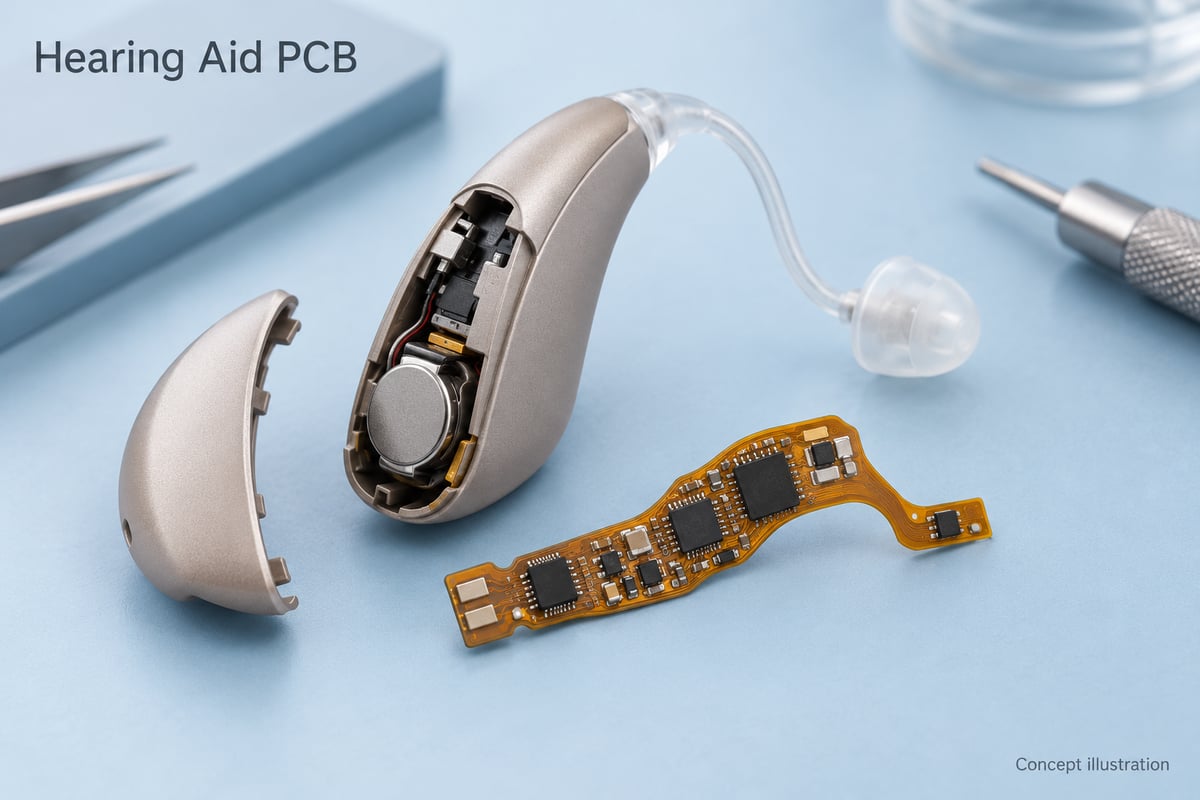
What Does a Hearing Aid PCB Connect?
A hearing aid circuit board connects the electronics that capture, process and reproduce sound. Its layout also accommodates power, controls and wireless connections where the design requires them.
The audio path is simple: microphone → processing and amplification → receiver → sound delivered to the ear.
The board connects three main groups:
- Audio components: Microphone interfaces, the processor and receiver connections carry the sound signal through the system.
- Power components: Battery connections and power-management circuitry supply the electronics; rechargeable designs also need the appropriate charging functions.
- Controls and communication: Buttons, programming connections and wireless circuitry support the selected product features.
The receiver—the miniature sound-producing transducer—may sit away from the main board. Its location therefore affects the interconnection layout. The PCB carries the circuit; the components and firmware perform the audio processing.
When Should a Hearing Aid Use Flex or Rigid-Flex PCB?
Choose flex when connections must reach different planes or pass around obstacles. Choose rigid-flex when those connections also need rigid component-mounting areas. A small rigid board can still work when the housing provides a suitable flat space.
| Board type | Best fit | Main constraint |
|---|---|---|
| Rigid PCB | Flat mounting space | Separate interconnections |
| Stiffened flex | Thin, shaped routing | Local support needed |
| Rigid-flex PCB | Connected rigid sections | More complex fabrication |
Flexible PCBs can replace some separate wiring. A local stiffener supports components on a flex circuit, but it does not provide the electrical layer structure of a rigid section in a rigid-flex PCB.
Choose the simplest structure that fits the populated assembly. Extra layers and more complex construction only help when they solve an actual routing or packaging problem.
How Can the PCB Fold Around the Battery and Receiver?
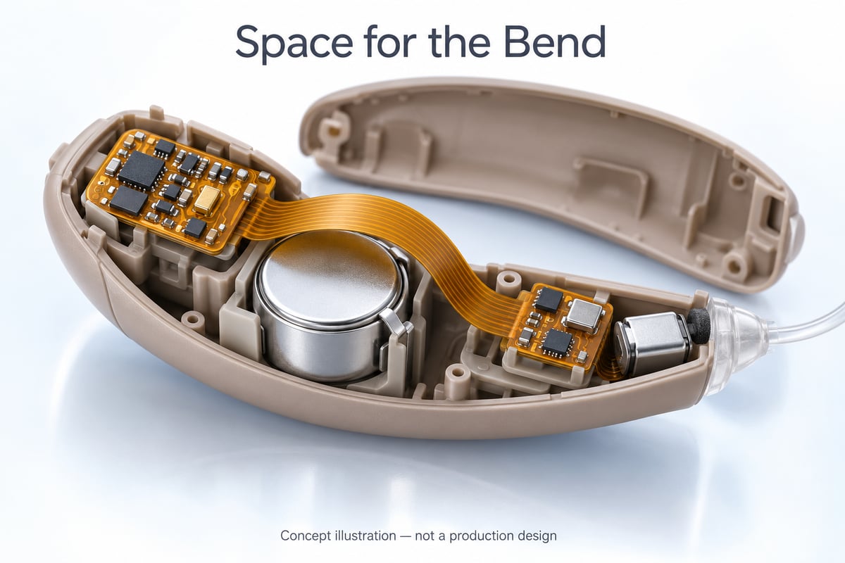
Place flexible connections between supported component areas, then evaluate the populated board inside the housing. The fold needs its own space; fitting the flat board outline is not enough.
Three details determine whether the arrangement is practical:
- Bend clearance: Leave room for a controlled curve around the battery or receiver. A sharp crease can damage the flexible circuit.
- Component support: Keep the intended bend away from soldered component areas. Review stiffener ends so bending does not concentrate strain near a joint. Reviewing stiffener transitions and bend placement can also help reduce the risk of flex PCB delamination.
- Installation access: Allow the assembly to pass contacts and internal features without forcing the flex into a tighter bend than intended.
For hearing aid PCB design, distinguish a one-time installation bend from repeated movement during use. The allowable bend depends on the construction and use conditions; one universal radius is not suitable for every stackup.
How Can PCB Layout Reduce Noise in the Microphone Signal?
Keep sensitive microphone signals away from interference sources while preserving appropriate return paths. In a small housing, the relationship between adjacent circuits matters as much as trace length.
Focus on these three areas:
- Microphone routing: Follow the selected microphone and processor documentation. Analog outputs and digital interfaces need different treatment.
- Power and return paths: Evaluate decoupling, switching loops and grounding together. Separating functional areas does not automatically require a split ground plane.
- Operating modes: Check for interference during wireless activity or charging where applicable, rather than testing only an idle board.
Also separate electrical noise from acoustic feedback between the receiver and microphone: rerouting a trace will not solve every acoustic issue.
How Can a Hearing Aid PCB Resist Moisture and Sweat?
Combine compatible assembly processes, selective protection and a suitable enclosure. Board coating alone does not establish a waterproof rating for the hearing aid.
The protection plan needs to address three practical concerns:
- Keep sound ports clear: Coating or contamination at the microphone opening can interfere with sound capture.
- Preserve working contacts: Charging contacts, connectors and other exposed interfaces may need defined coating exclusions.
- Match cleaning to the microphone: Some MEMS devices prohibit washing after reflow. Select the cleaning and protection process before building the assembly.
For example, the Knowles MM25 application note restricts washing and ultrasonic processing. Use the instructions for the actual microphone, then verify environmental performance with the intended housing and assembly.
What Makes Miniature Hearing Aid PCB Assembly Difficult?
Small pads, flexible substrates and sensitive acoustic components leave little room for process variation. Reliable assembly depends on controlling the board and the components together.
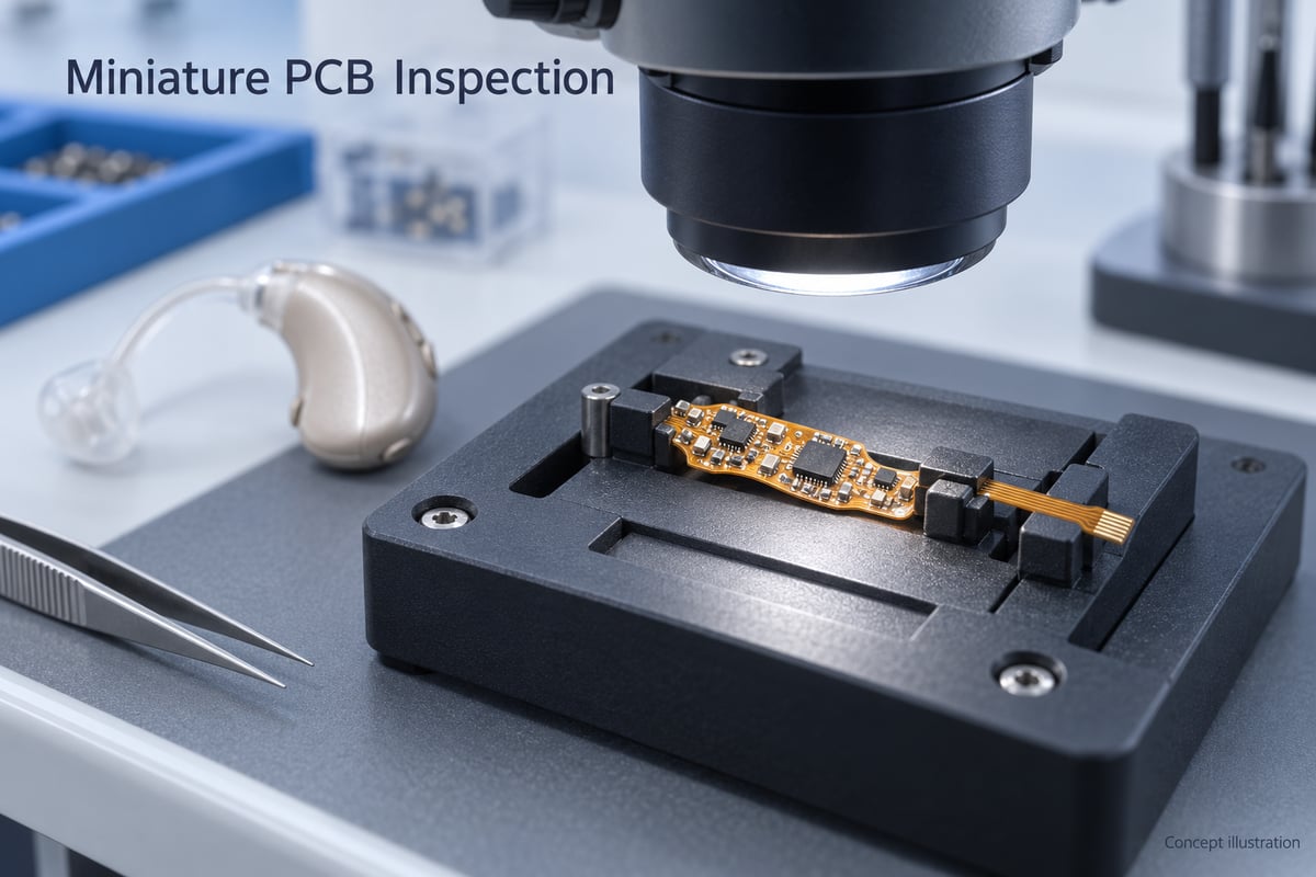
- Stable support: Use an appropriate carrier or fixture to hold component areas during printing, placement and soldering.
- Controlled soldering: Match land patterns, solder deposits and reflow conditions to the selected packages.
- Protected microphones: Follow the device’s handling and acoustic-port restrictions throughout processing.
- Suitable inspection: Choose inspection methods for the joints present, including those that surface inspection cannot fully assess.
Permanent stiffeners remain inside the product; temporary assembly fixtures do not. Account for that difference when judging available housing space.
Hearing aid PCB assembly does not automatically require bare die or the smallest passive components. Those choices should follow the circuit and space requirements, with a process that can be repeated consistently.
Which Tests Matter Before the Board Goes into the Hearing Aid?
Test the bare board, populated assembly and complete device at the appropriate stages. Each answers a different question about whether the product will work.
| Stage | Main check |
|---|---|
| Bare PCB | Continuity and isolation |
| Populated board | Components and solder joints |
| Powered assembly | Audio path and operating current |
| Installed device | Fit and final performance |
The sequence matters for two reasons:
- Access becomes limited: Test functions that will be difficult to reach before closing the housing, where practical.
- Installation can introduce faults: Folding, connections and acoustic assembly can change the result, so repeat the relevant checks in the finished configuration.
Agree on the PCBA test coverage and fixtures before production. Board-level acceptance does not replace the product developer’s complete hearing-aid validation.
Why Choose BestFPC for Your Hearing Aid PCB?
BestFPC offers flexible circuits, rigid-flex boards and FPC assembly services. For a compact hearing-aid project, this allows the board construction and assembly requirements to be discussed together.
The practical benefits are:
- Several construction options: Compare supported flex and rigid-flex according to component positions and available folding space.
- Manufacturing and assembly alignment: Review the outline, stiffeners and populated areas together so the proposed board can also be handled during assembly.
- A defined supply scope: Discuss bare-board or populated-assembly supply, with inspection and functional testing matched to the agreed build.
For hearing aid PCBs, specific package sizes, protective treatments and test requirements still need project evaluation. BestFPC’s role is to support the agreed board manufacturing and assembly scope around your circuit requirements.
FAQs about hearing aid PCB
Can a hearing aid use a standard rigid PCB?
Yes, if the populated board and connections fit the housing. Flex becomes useful when connections must reach different planes or pass around internal parts.
Does every hearing aid PCB need HDI technology?
No. Use HDI when component pitch and routing density require it. The decision follows the layout, not the hearing-aid label alone.
What is the difference between a hearing aid PCB and PCBA?
A PCB is the fabricated board; a PCBA includes the assembled components. Firmware loading, functional testing and housing integration are additional activities with separately defined scope.
Can a working prototype move directly into volume production?
A working sample is a starting point. Volume production also needs repeatable fabrication and assembly, suitable inspection coverage, and validation of the intended materials and mechanical configuration.
Ready to discuss your hearing aid PCB build? Send your board files, expected quantities and housing constraints to sales@bestfpc.com. For assembly, include the BOM and placement data so BestFPC can evaluate the manufacturing scope and quotation.


.png)
.png)
.png)
.png)

.png)