


 2026-11-10

 BEST
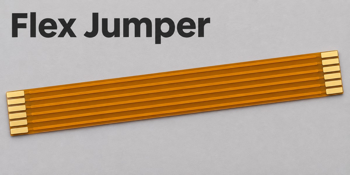
A flex jumper is a flexible interconnect used to link circuit boards or bridge connections within an electronic assembly. When manufactured as an etched flexible printed circuit, the jumper itself is an FPC. Its outline, conductor routing and end contacts can be customized to fit the product’s internal geometry.
At BestFPC, we manufacture custom FPC for use as flexible jumpers in board-to-board connections at our facilities in China. Our engineers review your circuit drawings for manufacturability, while prototype and small-batch production lets you evaluate the fabricated FPC before scaling up. Send your FPC files and interface requirements to sales@bestfpc.com to discuss fabrication options.
FPC Construction Options for a Flex Jumper Cable
We manufacture custom FPC that can serve directly as a flex jumper cable, using etched copper circuitry on polyimide with the layer count and outline matched to your drawings. Single-sided and double-sided options can serve straightforward links or routing that needs a second copper layer.
The appropriate construction depends on what the connection must do:
- Straight connections: A simple printed jumper can connect matching endpoints without additional branches. If an available FFC jumper already meets the mechanical and electrical requirements, custom fabrication may offer little benefit.
- Shaped or remapped connections: Etched routing allows an offset outline, a branch or a different pin arrangement at each end. Passive copper routing changes connections; it does not convert signals or voltage levels.
- Connections requiring assembly: If the FPC requires mounted connectors or other components, include the BOM and assembly drawing. Specify bare-FPC fabrication or FPCBA in the RFQ so the quotation identifies exactly what will be supplied.
Flat flex ribbon jumper cables can refer to different constructions, including FFC and etched FPC. “Flex jumper” describes the connection’s function, while “FPC” identifies its circuit construction. This article focuses on the FPC type; it can be supplied with exposed contact fingers or solder pads without mounted connectors.
Flat Flex Jumper Cable Termination Options
Choose flat flex jumper cable terminations around whether each endpoint must disconnect for service or remain soldered in place. Specify both ends separately, including their contact orientation and pin numbering.
| Termination pair | Service access | Assembly requirement |
|---|---|---|
| ZIF tail / ZIF tail | Disconnect either end | Compatible connector at each board |
| ZIF tail / solder pads | Disconnect one end | Access to the fixed solder joint |
| Solder pads / solder pads | Desolder for removal | Support and access at both joints |
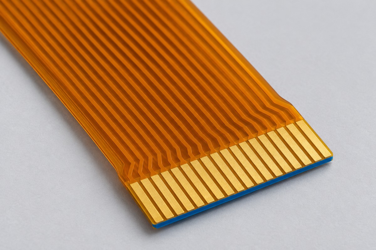
A flex PCB connector match requires more than the correct pitch. A flexible circuit connector drawing also defines contact engagement, insertion depth and the permitted tail thickness. For flex PCB connectors at opposite ends, verify the requirements independently rather than assuming identical tails.
- Tail thickness: Add the local FPC, adhesive and stiffener thicknesses present in the insertion zone. Check the complete tolerance range against the connector specification.
- Contact arrangement: Show the exposed contact side and pin 1 viewing direction. Same-side contacts do not, by themselves, establish the correct electrical mapping.
- Soldered termination: Define exposed copper, coverlay openings and reinforcement boundaries. For hot bar soldering, the joint must allow thermode access and adequate support; we review the FPC structure for the intended joining method.
A ZIF-ended FFC and an FPC jumper can require different tail constructions even when they fit similar housings. Treat a flex circuit connector or another flex-to-board connector as a specified mating interface, not a generic substitute.
Flex Circuit Manufacturing Capabilities for Custom Jumpers
We manufacture custom FPC for flex jumper applications with 1–4 copper layers and 0.06–0.60 mm finished board thickness in our standard pure-flex process. Our material, conductor and reinforcement options let us match the fabricated circuit to your approved routing and connector-interface requirements.
Our manufacturing capabilities for a custom flexible circuit include:
| Manufacturing Item | Standard Capability |
|---|---|
| Adhesive-based PI core | 0.5, 1 or 2 mil PI |
| Adhesive-based core copper foil | 0.33, 0.5 or 1 oz |
| Adhesiveless PI core | 0.5, 1, 2 or 3 mil PI |
| Adhesiveless core copper foil | 0.33, 0.5, 1 or 2 oz |
| External line width/spacing | 3.5/3.5, 4/4 or 8/8 mil |
| PI stiffener thickness | 3, 5, 7 or 9 mil |
| Contact finishes | Immersion gold, plated gold, OSP, tin plating |
The listed line width/spacing values correspond to 18, 35 and 70 μm finished copper, respectively, before manufacturing compensation. We review PI and copper selections together against your stackup requirements. Connector-tail thickness includes the FPC, adhesive and stiffener; specify the required total thickness and tolerance on the drawing. Include any contact-plating requirements with the selected surface finish.
For flex circuits carrying power, we also review conductor width and copper thickness against your stated current and temperature-rise requirements. Material options and process limits are assessed together during DFM review; they are not a guarantee that every listed limit can be combined in one build.
FPC Manufacturing for Flex Jumper Routing Requirements
A custom flex jumper can accommodate board offsets and enclosure obstacles by changing the routed shape and available flexible length. We review the manufacturability of your FPC outline, reinforcement and bend-region layout. Your product team defines the installed path and verifies that the connection does not require stretching or sharply folding the circuit.
- Control board to an operator panel: Where the panel sits above or beside the main board, a shaped route can follow the available enclosure space. Provide the endpoint positions and installed orientation so the jumper length reflects the actual path, not just the straight-line distance.
- Instrument main board to an I/O daughterboard: An offset outline can route around a mounting post or adjacent component. Check clearance in the assembled enclosure, including tolerances and the space needed to make the connections.
- Boards accessed during servicing: Allow enough free length for the intended service movement. Place supports so opening the assembly does not pull directly on the connector tail or solder joint.
Define the bend region separately from reinforced ends. A drawing showing the installed shape and attachment points is more useful for this review than a flat outline alone.
FPC Preparation for Custom Flex Assembly
We manufacture FPC with the pads, reinforcement and panel format required by your custom flex assembly process. For flexible circuit assemblies, you can specify bare FPC for your assembler or request an FPCBA quotation with the component and assembly scope defined.
For flex PCB assembly, provide the BOM, assembly drawing and component orientation requirements alongside the circuit files. This lets us check the FPC fabrication features needed for downstream handling and assembly.
- Connector interface: Provide the complete part number and mounting drawing so we can review the FPC pad layout and reinforcement against your files. Assign component procurement to the agreed supplier and approve substitutions before purchasing; a similar pitch does not establish mechanical equivalence.
- Assembly support: Plan stiffeners and carrier support around component placement and soldering. Keep the working bend outside the supported mounting area.
- Delivery format: Confirm whether the assembler needs panels or separated pieces. Rails, locating features and separation method can change how the flex circuit assembly is handled downstream.
For each flexible circuit assembly, distinguish the fabrication drawing from the assembly drawing. Identify any connector installation included in the FPCBA order, and define the board attachment and system integration work that remains for your team.
FPC Quality Inspection for Flex Jumper Applications
For bare FPC, we inspect the fabricated circuit against the approved netlist and manufacturing drawing. For FPCBA, agree the additional assembly inspection requirements before production. Your product team verifies the installed interface and route in the finished equipment.
| Inspection area | Check | Acceptance basis |
|---|---|---|
| Circuit connections | Opens and shorts | Approved netlist |
| Connector tails | Thickness and contact geometry | Mating drawing and tolerances |
| Coverlay and stiffeners | Position and condition | Fabrication drawing |
| FPC outline | Dimensions and cutouts | Approved outline and tolerances |
Define the inspection scope before order release. Measure reinforced contact areas against their local requirements instead of applying one overall thickness value to the entire jumper.
Your product qualification plan should define bend-life, environmental and functional testing of the completed interconnect. These checks are distinct from FPC fabrication inspection and need their own test conditions and acceptance limits.
FPC Prototyping for Flex Jumper Applications
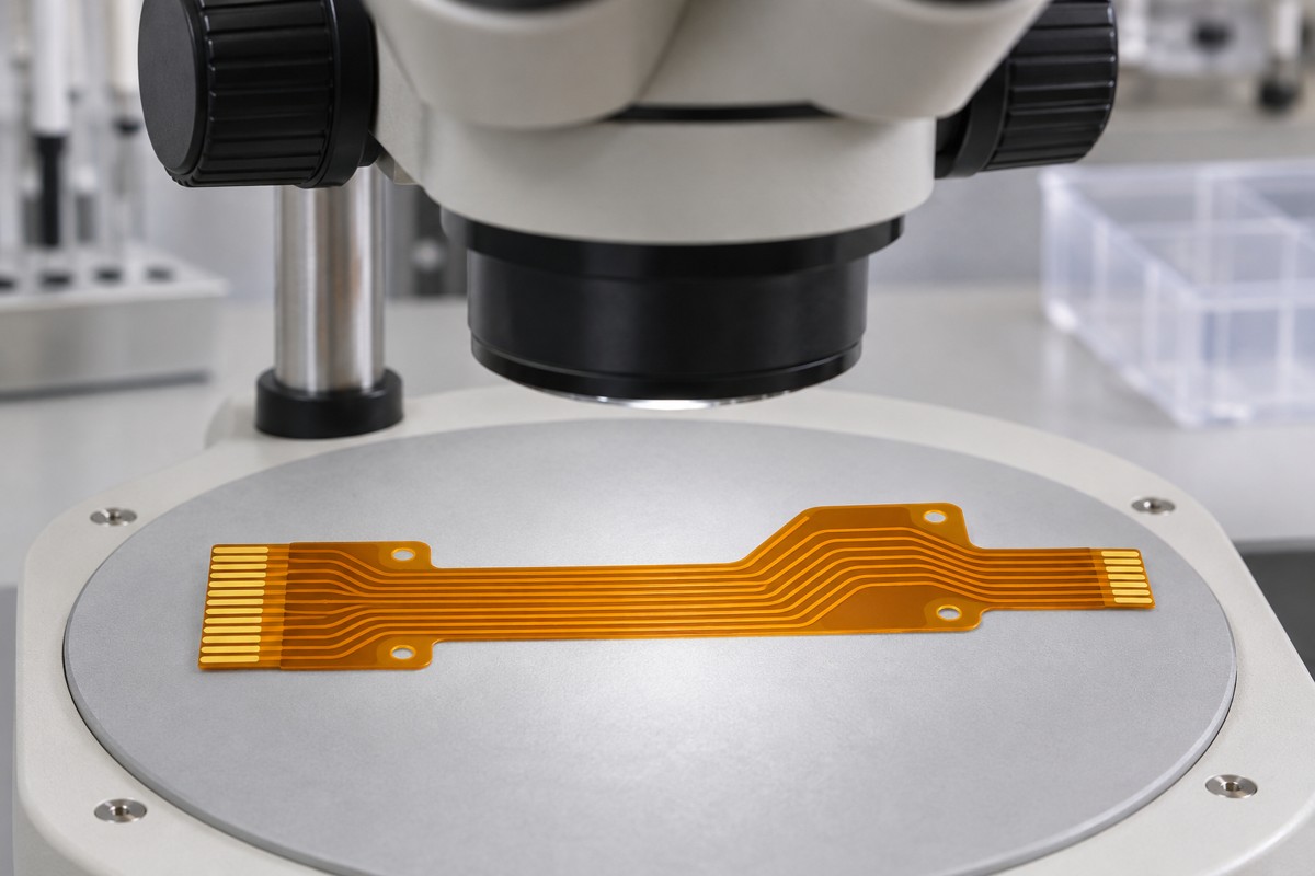
We fabricate prototype and small-batch FPC so your team can assemble and evaluate the interconnect in its intended hardware before committing to production. The useful outcome is a confirmed interface and installation, with any required changes captured in the next drawing revision.
Focus sample evaluation on three areas:
- Connector Fit: Check insertion, latching and contact orientation using the specified connector and mating boards.
- Assembly Fit: Install the enclosure and nearby components, then inspect the route for interference, trapped sections or tension at the ends.
- Handling Durability: Evaluate installation and service movement under the product’s requirements rather than judging flexibility by hand alone.
Record the accepted outline, stackup, reinforcement and assembly configuration. If a sample requires modification, update the production files and approve the revision before scaling the order.
What Affects FPC Cost in a Flex Jumper Project?
The FPC portion of flex jumper cost depends on circuit construction, material utilization and order quantity. Compare quotations against the same specification, separating recurring unit prices from applicable tooling and fixture charges.
- Material and stackup: Additional layers, thicker copper or special materials change fabrication requirements. Select them for an electrical or mechanical need rather than adding them as a general reliability measure.
- Outline and panel utilization: Length, branches and unusual shapes influence how circuits fit on a production panel. Review nesting options while preserving the required installed geometry.
- End preparation: Reinforcement and contact finishes contribute to the FPC fabrication price. Purchased connectors and downstream assembly add separate costs to the completed interconnect; they are not included in a bare-FPC quotation.
- Quantity: Request sample, pilot and production pricing against the same file revision to understand how setup costs are distributed.
Include Gerber files, the fabrication drawing, quantities and required delivery format in the FPC RFQ. This gives the quotation a clear manufacturing basis and reduces price changes caused by missing requirements.
FPC Manufacturing Lead Time for Flex Jumper Projects
Our rapid-delivery policy offers 1.5-week FPCBA delivery for projects that include flexible PCB assembly. For your flex jumper application, specify whether the order covers bare FPC fabrication or FPCBA so we can confirm the applicable delivery schedule against the approved files, material availability and order quantity.
To plan your delivery:
- Production Release: Resolve drawing discrepancies and confirm the stackup before release. For FPCBA, also provide the approved BOM and assembly drawing so we can confirm the rapid-delivery scope and schedule.
- Material Readiness: We review the availability of specified FPC laminates and stiffeners, plus components required for an FPCBA order. These checks establish whether the requested build can follow the 1.5-week rapid-delivery schedule.
- Bare-FPC Orders: If your team handles assembly, we confirm the FPC fabrication schedule separately. Allow additional time for your component procurement, assembly and system testing.
- Shipping Arrangements: State the required receipt date and destination so the quotation can distinguish the production schedule from transport and destination clearance.
Send your files, quantities and required receipt date with the RFQ. We will confirm the delivery scope and schedule for the bare FPC jumper or the specified FPCBA build.
Why Choose BestFPC for Flex Jumper FPC Manufacturing?
BestFPC manufactures custom FPC jumpers from your approved circuit drawings, with engineering review of the outline, stackup and interface features. Prototype and small-batch support lets you evaluate the construction before scaling production.
- Quality-system qualifications: Our qualifications include ISO 9001, ISO 13485, IATF 16949 and AS9100D. We can provide the applicable certification documentation for supplier qualification; system certification does not certify the finished device.
- Experienced engineering support: Our team includes R&D and PCB/PCBA engineering expertise backed by 20 years of experience. DFM pre-review reports identify FPC manufacturing issues before production, helping your team resolve drawing or stackup discrepancies.
- Own PCB and PCBA factories: Our manufacturing resources support FPC fabrication and assembly within the agreed order scope. For FPCBA projects, coordinating the circuit files, BOM and assembly requirements helps resolve issues that affect both fabrication and component mounting.
- Prototype and small-batch support: Start with the quantity needed for hardware evaluation, then carry the approved construction into later orders. This supports development without requiring the first build to serve as full production approval.
FAQs about Flex Jumper
Can a custom flex jumper replace a standard FFC cable?
It can be considered when the required shape or routing exceeds what a standard FFC provides. Replacement still requires verification of both interfaces, electrical mapping and the installed mechanical path.
Can the two ends have different pitches or pin arrangements?
Etched routing can accommodate different endpoint layouts where the geometry and manufacturing limits permit. Supply the mating drawings and required connection map; passive routing cannot perform protocol or voltage conversion.
Can you manufacture the FPC for assembly by our own team?
Yes. We manufacture the FPC according to your approved circuit files. Specify the panel format and handling requirements so the fabricated boards suit your assembly process.
Is a flex jumper suitable for repeated movement?
Only when its construction and installed route are designed and validated for that duty. An installation bend does not establish a repeated-flex lifetime.
Do you need a physical sample before preparing a quotation?
Not necessarily. Complete circuit files and mechanical drawings can support quotation review. If a replacement part has undocumented features, a sample may help identify missing details, but it does not replace approval of the manufacturing specification.
What happens if the specified tail thickness conflicts with the connector drawing?
Resolve the discrepancy before fabrication. Confirm the connector revision and local stackup, then approve a drawing that states the required finished thickness and tolerance.
BestFPC combines experienced engineering support, in-house FPC manufacturing, and prototype and small-batch production to help you move from design review to hardware validation. Our engineers review your drawings for manufacturability and provide DFM feedback before production. Send your circuit files, mating-interface specifications, and required quantities to sales@bestfpc.com for a manufacturing review and quotation.


.png)
.png)
.png)
.png)

.png)