


 2026-11-05

 BEST
A capacitive sensor PCB uses conductive electrodes to detect changes in capacitance associated with touch or proximity. For curved control panels, a flexible circuit can place those electrodes behind the user interface while routing connections through a compact tail. Successful procurement starts with defining the electrode board, its mounting stack, and the electronics that will read it.
At BestFPC, we manufacture custom flexible circuits using polyimide materials, coverlay, and local stiffeners to suit your drawings. These options help match the sensing area to the panel shape and the connection tail to its mating interface. Send your fabrication files and panel requirements to sales@bestfpc.com so we can review the construction and define the manufacturing scope for your quotation.
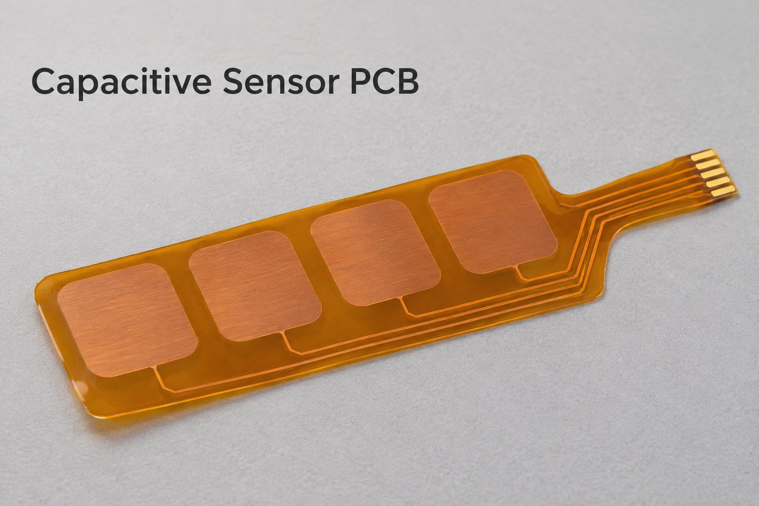
Custom Capacitive Sensor PCB Manufacturing
We manufacture flexible electrode circuits to customer-supplied patterns and fabrication drawings. A PCB capacitive touch sensor may use a separate controller board, so purchasing the electrode circuit does not automatically include the sensing electronics or firmware.
A capacitive touch sensor on a PCB can use etched copper as the sensing electrode. The term capacitive PCB describes that sensing function; it does not specify the complete assembly you will receive.
Define the deliverable before requesting a quotation:
- Bare electrode circuit: Copper patterns, insulating layers, connection pads, and specified reinforcement.
- Electrode circuit with an integral tail: The sensing area and connection route manufactured as one flex circuit.
- Assembled board: A separately defined scope requiring the BOM, component locations, and assembly requirements.
Identify the electrical interface and the mechanical boundary on the drawing. This prevents a quotation for a bare flex from being compared with one that includes components, programming, or functional testing.
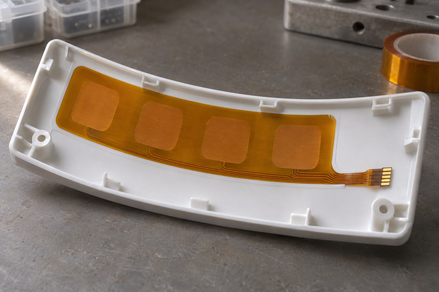
Flexible Sensor Boards for Curved Touch Panels
Flexible sensor boards let the electrode area follow a curved panel while a connection tail folds around the enclosure. A rigid board may be sufficient for a flat, well-supported interface.
- Panel shape: For PCB capacitive sensors in an appliance control strip or equipment keypad, provide the installed shape alongside the flat manufacturing outline.
- Sensing area and tail: A capacitive touch flex PCB can combine shaped electrodes with a narrow tail; identify the bonded sensing area separately from the section that bends during installation.
- Type of movement: State whether the circuit bends only during assembly or repeatedly in service so the construction can be assessed for the intended use.
- Local reinforcement: Place stiffeners around connectors and component areas, keeping their edges outside the intended bend; show these boundaries on the mounting sketch.
Materials and Stackup for a Flexible Capacitive Touch Layer
A flexible capacitive touch layer needs a defined material stack from the electrode to the touch surface. The FPC coverlay protects the circuit, while the external glass or plastic overlay forms the surface the user touches; these are different parts of the assembly.
Our material options include adhesive-based and adhesiveless polyimide cores, coverlay, bonding materials, and PI stiffeners. An adhesiveless core describes the copper-to-polyimide construction. It does not mean that the sensor requires no adhesive when attached to the panel.
| Stack element | Drawing requirement |
|---|---|
| Copper electrode | Pattern, layer, copper thickness |
| Polyimide core | Material grade and thickness |
| Coverlay | Film, adhesive, opening locations |
| Panel bonding layer | Adhesive grade and coverage |
| External overlay | Material and finished thickness |
| Local stiffener | Position and finished assembly thickness |
Air gaps and changes in dielectric thickness can alter the touch signal. Specify the mounting adhesive and bonding coverage alongside the FPC construction, then evaluate the prototype with the intended panel. A change in adhesive or coverlay should enter the engineering change process rather than being treated as a purchasing-only substitution.
Capacitive Touch Sensor PCB Layout Checks Before Fabrication
Capacitive touch sensor PCB layout checks should establish whether the released copper pattern, insulation, and connection features can be manufactured as specified. Electrical geometry must also follow the selected controller's guidance; a fabrication review cannot replace that controller-specific evaluation.
Resolve these items before releasing the manufacturing files:
- Electrode identity: In a capacitive sensor PCB design, label sensing, transmit, receive, ground, and shield nets clearly. Keep the artwork and netlist consistent.
- Pattern dimensions: State critical electrode gaps and dimensions on the drawing. Do not substitute a factory's minimum trace spacing for the spacing required by the sensing design.
- Ground and shield construction: A thin flex brings adjacent copper layers closer together. Review the ground pattern instead of copying a solid plane from a thicker rigid board; grounded copper and a driven shield serve different functions.
- Routing and coupling: In capacitive touch sensor PCB design, interelectrode capacitance and trace coupling depend on geometry. Identify critical areas where copper changes require the electronics designer's approval.
- Production acceptance: A capacitive touch PCB design should identify inspection dimensions, electrical test access, and the revision of the controller reference used by the design team.
Keep proposed manufacturing adjustments separate from the released artwork until approved. An altered pad, added copper fill, or rerouted sensing trace can be electrically significant even when the board remains free of shorts and opens.
Flex Tails, Stiffeners, and Controller Assembly
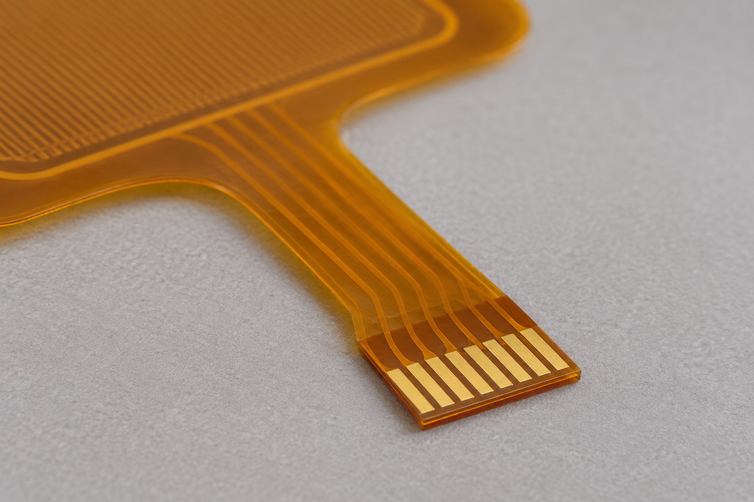
A flex tail must match the connector's contact orientation, pitch, insertion geometry, and specified thickness. For a capacitive touch PCB, these mechanical details also help keep the sensing interconnect stable during operation.
Include the following connection and assembly details:
- Connector part number: Confirm which side contacts the exposed pads and the required insertion depth.
- Finished tail thickness: Specify the complete reinforced stack, including adhesive, rather than the stiffener thickness alone.
- Bend and support locations: Show the installed fold and how the tail is retained near the connector.
- Component area: For an assembly quotation, provide the BOM and placement data, with the supported component region identified.
A longer sensing tail is not electrically interchangeable with a shorter one. It adds conductor length and can change parasitic capacitance and noise pickup. If the controller location changes, have the electronics team reassess the interconnect before freezing the flex outline.
Capacitive Sensor PCB Inspection and Prototype Validation
Capacitive sensor PCB acceptance should separate conformity to the fabrication drawing from performance in the finished touch system. Agree on the inspection scope before production so both parties know what constitutes an acceptable board.
| Acceptance stage | Items to define |
|---|---|
| Fabricated circuit | Opens, shorts, dimensions, appearance |
| Mechanical fit | Tail insertion, reinforcement, installed shape |
| Assembled electronics | Placement, soldering, programming requirements |
| Touch system | Detection, false triggers, operating conditions |
For functional validation, supply the controller configuration, firmware revision, representative panel, and written acceptance criteria. Define the touch locations and relevant operating conditions, including gloves or moisture where the product requires them. These conditions are test inputs, not automatic properties of a flexible board.
Retain the approved sample configuration and its material revisions. When a later build changes the panel, adhesive, circuit construction, or controller settings, identify which validation results must be repeated before approving the change for production.
What Affects Prototype Cost and Production Lead Time?
Prototype cost depends on the circuit construction, material availability, tooling, and any assembly or test work included in the order. Lead time also depends on when the complete manufacturing package is approved and whether the specified materials and components are available.
The main quotation drivers are:
- Circuit construction: Layer count, copper pattern complexity, and overall dimensions.
- Panel utilization: Irregular outlines and long tails can reduce the number of circuits produced from a panel.
- Secondary operations: Reinforcement, shaped adhesive, and additional handling or alignment steps.
- Assembly scope: Component sourcing, programming, and fixture preparation when required.
- Order quantities: Prototype quantity and expected repeat volumes affect setup-cost allocation.
Ask for tooling and other one-time charges to be separated from the unit price. Compare quotations against the same drawing revision and delivery scope. Releasing an incomplete package may produce an early price, but it leaves construction changes and schedule adjustments unresolved.
Ordering Custom Sensor Boards for USA Projects
For USA projects, BestFPC provides a China-based manufacturing route for custom flexible circuits. A useful RFQ defines the board to be supplied, the documents governing acceptance, and the delivery destination.
As a supplier of capacitive touch sensor flex circuits, we can discuss PI construction, coverlay, and local reinforcement against your fabrication package. Keep system design ownership clear so manufacturing questions reach the right engineer and electrical changes receive approval.
Send the following information with your inquiry:
- Fabrication package: Gerber files, drill data where applicable, netlist, and a revision-controlled drawing.
- Mechanical requirements: Flat outline, installed shape, stackup, connector details, and reinforcement locations.
- Panel information: Overlay material, thickness, and bonding arrangement.
- Order plan: Prototype quantity, expected production quantities, requested delivery date, and US destination.
- Additional scope: BOM and placement files for assembly; firmware, fixture information, and acceptance criteria for requested functional testing.
Confirm shipping terms, freight responsibility, and required shipment documentation when reviewing the quotation. Manufacturing completion and arrival at your facility are separate dates, so the purchasing schedule should account for both.
FAQs about Capacitive Sensor PCB
Is a PCB capacitance sensor the same as a PCB capacitor?
No. A PCB capacitance sensor detects a change associated with a target, such as a finger. A PCB capacitor usually refers to a capacitor component or a structure intended to provide capacitance within a circuit. Specify the sensing function when requesting a board quotation.
Can the electrodes work behind a metal panel?
An ordinary touch-electrode arrangement should not be assumed to work through a continuous metal panel. Metal-touch interfaces require a suitable sensing architecture and mechanical construction. Identify the metal panel early so the electronics team can select and validate the appropriate approach.
Is ITO required for a non-transparent touch panel?
No. Copper electrodes can serve an opaque touch interface. Transparent electrode materials such as ITO are relevant when the sensing area must also transmit light. Specify any illuminated regions separately from opaque electrode areas.
Can the sensor be validated before the enclosure is final?
Early prototypes can check selected electrical and mechanical functions. Final touch performance still needs evaluation in the intended installation, because the panel, mounting arrangement, and nearby materials form part of the sensing environment.
Can one flex circuit combine touch electrodes and an LED interface?
Potentially, provided the layout accommodates the LEDs, their connections, and the required support. LED routing and switching activity need consideration near sensing traces. Include the lighting arrangement in the design review instead of adding it after the sensor artwork is approved.
Do you need firmware and a test fixture for assembled-board testing?
Functional testing needs an agreed configuration and a repeatable method of stimulating the sensor and checking its output. Firmware and a fixture may be required, depending on the board. Specify who supplies them, how revisions are controlled, and what defines a pass.
BestFPC can help turn your approved electrode drawings into a defined flexible-circuit manufacturing package. Our R&D and PCB/PCBA engineers bring 20 years of experience to DFM pre-reviews and process recommendations for your sensor board's stackup, electrode features, and connection details. We support prototypes and small batches so your team can evaluate panel fit and touch response before committing to production quantities. Send your files, panel requirements, and order quantities to sales@bestfpc.com to discuss construction options and request a quotation.


.png)
.png)
.png)
.png)

.png)