


 2026-10-14
 BEST
BESTA compact camera needs a PCB that fits the enclosure, supports the sensor and connects reliably to the host electronics. Choosing a camera module PCB manufacturer becomes easier when you know which board structure, assembly support and tests your project needs.
For action cameras and dash cams, three decisions deserve early attention: where the sensor sits, how the boards connect and where heat leaves the product. Start with these, then match the manufacturing scope to your design.
What Does a Camera Module PCB Manufacturer Deliver?
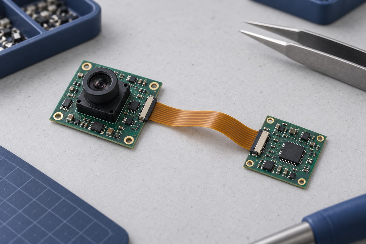
You can purchase a bare board, an assembled board or a complete camera module. Choose the delivery stage that matches the work your own team can handle.
- Bare PCB or FPC: Suitable when you already have an assembly partner. The manufacturer fabricates the circuit from your released design files.
- Camera module PCB assembly: Suitable when you need components mounted as well as the board manufactured. The order includes the agreed assembly inspection and testing.
- Complete camera module: Suitable when you need the sensor, optics and electronics supplied as an integrated module. Confirm whether focusing, optical alignment and image validation are included.
Optical work is a separate capability from PCB assembly.
If your camera circuit is already validated, focus your supplier discussion on board manufacturability, assembly quality and the required delivery stage.
Top 5 Camera Module PCB Manufacturers in China
The following five companies offer PCB or assembly services worth comparing for camera projects. This is an editorial shortlist based on published capabilities, not a market-share or quality ranking.
- BestFPC — Flexible circuits and local support. BestFPC offers FPC, rigid-flex and assembly services, with stiffener options for supported mounting areas. Consider it when your approved camera design needs a flexible connection and coordinated board manufacturing and assembly review.
- PCBWay — Camera-related rigid-flex construction. PCBWay publishes a camera-module PCB example using a four-layer rigid-flex structure with shielding film. This makes it a candidate to evaluate when your design requires integrated rigid and flexible regions.
- PCBONLINE — Camera PCB assembly. PCBONLINE advertises camera PCB assembly for industrial and consumer applications. Consider it when comparing assembly providers for sensor boards and associated camera electronics; define the required functional and image-testing scope.
- PCBMay — Custom camera boards. PCBMay lists camera PCB fabrication and assembly, including customization to supplied dimensions and layouts. It is an option to evaluate for a custom camera board built around an established design.
- RAYPCB — PCB fabrication and component assembly. Shenzhen-based RAYPCB offers custom board fabrication, component sourcing and assembly for prototypes and production. Consider it when your camera project needs these services under an agreed delivery scope.
Compare suppliers against the same camera design. Board construction, sensor handling, inspection coverage and delivery scope are more useful selection criteria than the position of a company in a list.
Should You Choose an Aluminum PCB, Flex PCB, or Rigid-Flex PCB for a Camera Module?
Choose the board around its main job: fixed support, flexible routing or heat transfer. A compact enclosure alone does not determine the right construction.
| Your main need | Board option to evaluate |
|---|---|
| Fixed component mounting | Rigid PCB |
| Metal-backed heat path | Aluminum-base PCB |
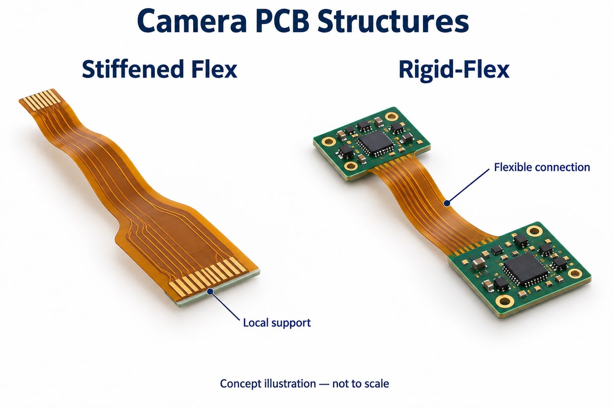
| Flexible tail with local support | Stiffened flex PCB |
| Rigid sections joined by flex | Rigid-flex PCB |
If you are looking for a camera module aluminum PCB manufacturer, first establish how heat will travel from the components to the cooling structure. An aluminum-base PCB uses circuit copper over an insulating dielectric and metal base; the dielectric also affects heat transfer.
For flexible designs, keep these distinctions clear:
- A flex PCB with FR4 stiffener adds local mechanical support without adding routed circuit layers.
- A rigid-flex PCB integrates electrically connected rigid and flexible regions.
- An aluminum stiffener on an FPC provides local reinforcement; it is different from an aluminum-base PCB.
Choose the simplest construction that meets the actual routing, support and thermal requirements.
How Should the Sensor Mounting Area and Flex Tail Be Arranged?
Support the sensor area and give the flex tail room to bend along its intended route. Treat the mounted sensor and flexible connection as two areas with different mechanical needs.
- Locate the sensor against the optics. Define the sensor position, lens-holder geometry and mounting references together. This makes the board’s role in the optical assembly clear.
- Route the tail in the assembled enclosure. Allow space for the bend, nearby components and connector insertion. A flat drawing alone cannot show every installation conflict.
- Match the bend to the construction. Distinguish a one-time installation bend from repeated movement. Bend radius depends on the flex construction and use conditions. For the flex tail, compare RA vs ED copper alongside the required bend conditions and complete stackup.
Sensor handling also belongs in the assembly plan. Follow the selected device’s reflow, cleaning and protective-film instructions to protect its optical surface.
How Are Multiple Camera Modules Connected in a Dash Cam?
Separate cameras inside the main housing from cameras mounted elsewhere in the vehicle. Connection distance and the selected interface determine the board and cable requirements.
- Nearby cameras: A short FPC or board-to-board connection may suit a sensor located close to the host board. Check connector orientation and available installation space.
- Remote cameras: A rear camera needs a link designed for the cable length and electrical environment. Its connection may require different electronics from a nearby sensor.
- Multiple inputs at the host: The receiving electronics must support the selected camera links and data paths. TI’s four-camera hub reference design, for example, receives FPD-Link III inputs and provides a MIPI CSI-2 output.
For the PCB order, turn that architecture into defined connector footprints, power connections and mounting positions. Extending a short sensor FPC into a remote-camera connection requires a new electrical and mechanical assessment.
How Does MIPI CSI-2 Affect the Camera PCB Stackup?
For CSI-2 over D-PHY, set the stackup before finalizing differential trace dimensions. The copper geometry and surrounding dielectric work together to produce the required impedance.
Focus on three connected decisions:
- Layer structure: Establish dielectric thicknesses and reference planes so the layout can use a defined routing structure.
- Signal routing: Apply the selected devices’ requirements for impedance, length matching, spacing and transitions.
- Manufacturing verification: Specify the impedance target, tolerance and agreed measurement method where controlled impedance is required.
Use the requirements of your own transmitter and receiver for numerical limits.
A verified board structure supports signal integrity; final link validation should include the connectors, interconnect and operating camera electronics.
How Can Camera PCB Heat Be Managed Inside a Sealed Action Camera?
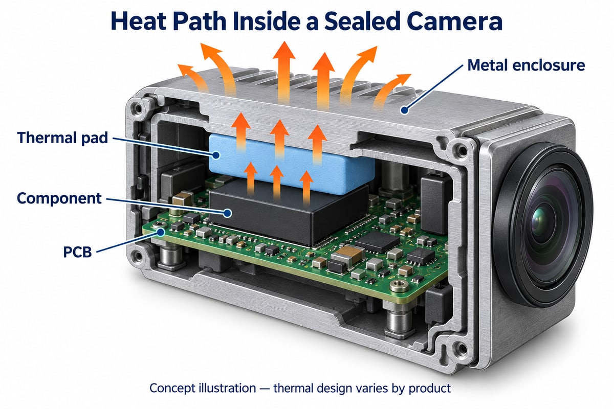
Build a continuous heat path from the devices through the board to the enclosure or heat spreader. Then test that path during sustained operation.
Move heat away from the components
Use copper areas, planes and thermal vias where the component package and electrical design allow. Follow the device’s thermal and assembly guidance.
Connect the PCB to the cooling structure
Where the design uses a thermal pad or similar interface, consider its thickness, insulation and contact pressure. The interface needs to bridge the intended gap without imposing unsuitable loading on the assembly.
Validate the closed camera
Test the actual enclosure under representative conditions:
- Sustained recording in the intended video modes.
- Display and wireless operation where applicable.
- Charging during recording, if the product supports it.
Monitor component temperatures and recording behavior. This connects the PCB thermal design to the customer’s real use: a camera that must continue operating inside its sealed housing.
Which Tests Verify the PCB, Assembly, and Camera Image?
Use each test to answer a specific quality question. Board connectivity, solder-joint quality and image performance need different checks.
| Quality question | Relevant check |
|---|---|
| Are circuits connected correctly? | Continuity and isolation |
| Does impedance meet the specification? | Agreed impedance measurement |
| Are components and joints acceptable? | Assembly inspection |
| Does the camera produce acceptable images? | Functional and image tests |
Bare-board electrical testing detects opens and shorts against the design data.
For camera module PCB assembly, build the inspection plan around the components and accessible test points:
- AOI: Inspect visible component placement and solder features.
- X-ray: Examine hidden joints where the package and inspection plan require it.
- Powered checks: Verify agreed electrical functions using a defined setup.
Image testing then uses the sensor, optics, host electronics and software together. Set application-specific criteria for focus, visible contamination and frame stability, and assign responsibility for these checks before production.
What Drives Camera Module PCB Manufacturing Cost?
Cost rises with construction complexity, tight tolerances and the work needed to assemble and verify the board. A smaller outline does not always mean a lower price.
The main cost drivers are:
- Routing density: Fine-pitch packages and dense connections can require more complex routing or hole structures.
- Board construction: Rigid-flex regions, extra lamination steps, stiffeners and shielding add manufacturing work.
- Mechanical requirements: Tight outlines, mounting positions and thickness tolerances affect fabrication demands.
- Assembly and testing: Component sourcing, tooling, inspection and functional-test fixtures contribute to the delivered cost.
Two useful opportunities to evaluate are simpler construction and better panel utilization. A stiffened flex circuit may satisfy a design that does not need rigid-flex, while tail shape influences how circuits fit on the production panel.
Compare quotations using the same quantities, construction, components and test scope. That makes the price difference meaningful.
Why Choose BestFPC as Your Camera Module PCB Manufacturer?
BestFPC brings flexible-circuit fabrication, rigid-flex options and assembly support into the same manufacturing discussion. For compact camera projects, this helps you evaluate the board structure alongside the way it will be mounted and assembled.
Match the construction to your available space
Our rigid-flex manufacturing services support designs combining rigid component areas with flexible connections. Bring your approved circuit and enclosure requirements so the proposed construction can be reviewed for manufacture.
Support mounting areas while retaining a flexible connection
Our FPC capabilities include multiple stiffener materials. These provide options for local support around connectors or component areas, with material and thickness selected against the project requirements.
Review the board and assembly data together
Our FPC assembly services include component sourcing and engineering-file review. Checking the BOM, placement data and component orientation helps identify discrepancies before assembly begins.
Ready to discuss your camera PCB? Send your Gerber files, stackup and mechanical drawing to sales@bestfpc.com. For assembly, include the BOM and placement data. We can review your requested construction and assembly scope and provide project-specific feedback and a quotation.
FAQs About Camera Module PCB Manufacturer
Can a camera PCB be reused with a different image sensor?
Only if the new sensor is compatible with the footprint, pinout, power requirements, interface and optical arrangement. Host software may also need changes. The same resolution or package size does not establish compatibility.
Does 4K or 8K resolution determine the PCB layer count?
No. Layer count depends on the circuit, package routing, interfaces, power distribution and available space. Choose the stackup from these design requirements.
Does a waterproof camera require a waterproof PCB?
Waterproof performance depends on the assembled product, including its housing, lens window and connectors. Board-level moisture protection, where needed, should form part of the overall sealing and environmental design.
Can one PCB design serve both an action camera and a dash cam?
Yes, if their electrical and mechanical requirements match. Compare sensor interfaces, power, mounting, thermal conditions and interconnections before reusing the design.
Planning your next camera PCB build? Contact BestFPC at sales@bestfpc.com to discuss your board structure, assembly needs and quotation. Share your Gerber files and mechanical requirements so our team can review the manufacturing scope for your project.


.png)
.png)
.png)
.png)

.png)