


 2026-11-05

 BEST
Rigid flex PCB material selection starts with one question: Will the flexible section bend only during installation or repeatedly during operation? The answer influences copper foil type, polyimide thickness, protective materials, and the finished stackup.
Polyimide (PI) is commonly used for flexible sections, while FR-4 provides mechanical support in rigid areas. However, choosing suitable individual materials does not guarantee that they will perform well together. This guide explains how to compare rigid-flex PCB materials, select an appropriate starting combination, and confirm the specifications before manufacturing.
What Materials Are Used in Rigid-Flex PCBs?
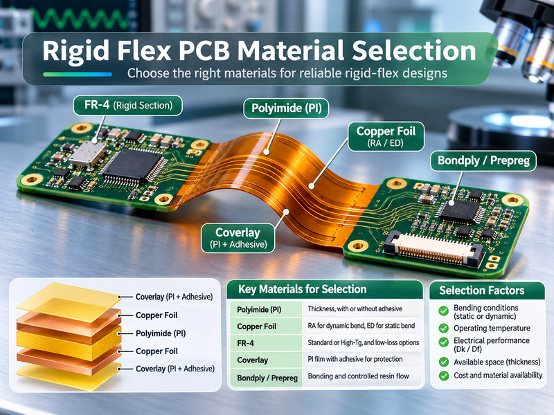
Rigid-flex PCBs typically combine polyimide, copper foil, FR-4, coverlay, and bonding materials. Each serves a specific function, so materials should be selected according to their position in the completed PCB.
| Material | Common Options | Selection Basis |
|---|---|---|
| Polyimide (PI) | Adhesive-based, adhesiveless | Flexibility, thickness, thermal properties |
| Copper Foil | RA, ED | Bend cycles, current, thickness |
| FR-4 | Standard, High-Tg grades | Thermal and mechanical properties |
| Coverlay | PI film with adhesive | Bending durability, insulation |
| Bondply | Flexible bonding films | Adhesion, dielectric thickness |
| Prepreg | Low-flow, no-flow | Resin flow, lamination requirements |
Common polyimide dielectric thicknesses include 12, 25, and 50 μm, depending on the product series. Frequently used copper foil thicknesses include 18 μm (approximately 0.5 oz/ft²) and 35 μm (approximately 1 oz/ft²).
These specifications are available material options, not universal design requirements. The final combination must satisfy the board's bending, electrical, and thermal conditions.
What Factors Determine Rigid-Flex PCB Material Selection?
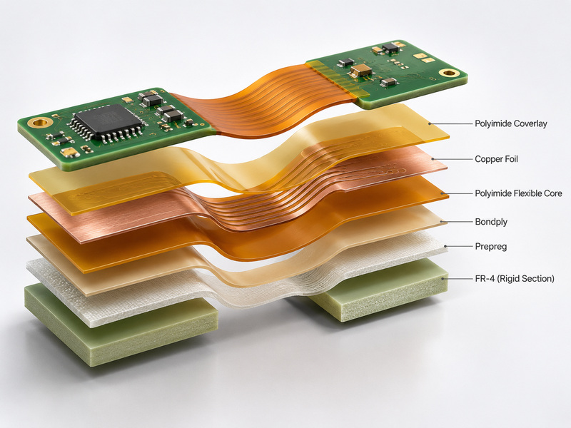
The correct material combination depends on bending conditions, operating temperature, electrical performance, and available space. These requirements should be established before selecting individual laminates.
Use the following criteria to narrow the options:
-
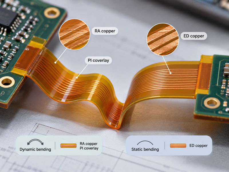
Static Bending: When the flexible section bends during installation and then remains stationary, qualified ED or RA copper may be suitable. The completed construction must tolerate the installation bend.
-
Dynamic Bending: For repeated movement, consider suitably qualified RA copper, a thin polyimide core, and PI coverlay. Required bend life must be verified under the actual operating conditions.
-
High Temperature: Choose dielectric and bonding materials with suitable thermal properties. Evaluate Tg, Td, and CTE for the rigid laminate and the thermal limits of the complete material system.
-
High-Speed Signals: Compare dielectric constant (Dk), dissipation factor (Df), and dielectric thickness at the operating frequency.
-
Limited Space: Reduce unnecessary flexible-layer thickness while maintaining dielectric strength, conductor capacity, and mechanical reliability.
The bending radius is especially important. A material combination suitable for a large bend radius may not survive a much tighter bend.
Before choosing a laminate, establish the required bend radius, expected cycle life, temperature range, conductor loading, and impedance requirements where applicable.
How Do You Choose Between Adhesive-Based and Adhesiveless Polyimide Laminates?
Adhesiveless polyimide is generally a better starting option when reduced thickness or demanding thermal performance is important. Adhesive-based laminates remain suitable when the additional adhesive layer meets the application requirements.
The main differences are:
-
Adhesiveless Polyimide: Copper is bonded to or formed on the dielectric without a separate adhesive layer at that interface. This can reduce laminate thickness and eliminate one adhesive interface.
-
Adhesive-Based Polyimide: A separate adhesive bonds the copper to the PI film. Its thickness and electrical and thermal characteristics must be included in the completed stackup.
-
Dielectric Thickness: Commercial adhesiveless laminates are available with nominal PI thicknesses such as 12, 25, and 50 μm. Availability varies by manufacturer and product series.
For a compact multilayer rigid-flex PCB, a 25 μm adhesiveless PI core can be a practical initial candidate. A thinner dielectric may be considered when bending strain or installation space is more restrictive, provided the insulation and manufacturing requirements remain satisfied.
Adhesiveless does not mean the entire PCB contains no adhesive. Coverlay and multilayer bonding materials may still use adhesive systems.
The final laminate should be identified by its approved material grade and construction, not by PI thickness alone.
How Should You Select Copper Foil Type and Thickness for Rigid-Flex PCBs?
RA copper is generally preferred for repeated bending, while ED copper can be suitable for static-flex applications. After selecting the foil type, choose a thickness that meets both electrical and mechanical requirements.
For copper foil type:
-
Rolled Annealed (RA) Copper: Commonly selected for dynamic flexible circuits because suitable RA grades offer favorable bending fatigue performance.
-
Electrodeposited (ED) Copper: Often used in static-flex constructions. Certain specialized ED foils can also support qualified dynamic applications, depending on the product and conditions.
For copper thickness:
-
12 μm (approximately ⅓ oz/ft²): A thin option for applications where minimizing flexible thickness is important and electrical requirements permit.
-
18 μm (approximately ½ oz/ft²): A common starting thickness for flexible circuits requiring a balance between flexibility and electrical performance.
-
35 μm (approximately 1 oz/ft²): Provides greater conductor cross-sectional area but increases stiffness and bending strain.
For the same conductor width and length, thicker copper reduces electrical resistance. However, additional thickness can make repeated bending more demanding.
For a dynamic-flex application, 18 μm RA copper may be a reasonable initial candidate, while thinner copper can be considered if current capacity and manufacturing requirements allow.
The copper foil grade, finished conductor geometry, and required bending life must still be validated. RA copper alone does not guarantee a particular number of bending cycles.
How Do You Select FR-4 Materials for the Rigid Sections?
Standard FR-4 is suitable when its thermal, mechanical, and electrical properties meet the application. More demanding thermal conditions may justify High-Tg FR-4, while high-speed signals may require a qualified low-loss material.
Make the selection according to the property that matters:
-
Standard FR-4: A practical option for many conventional rigid sections with moderate thermal and electrical requirements.
-
High-Tg FR-4: Consider when assembly processing or thermal cycling requires improved thermal performance. Check Tg alongside Td and CTE.
-
Low-Loss Materials: Evaluate when conventional FR-4 cannot meet the signal-loss or dielectric requirements at the operating frequency.
High Tg and low loss are not competing material categories. A laminate can have both properties, and some low-loss laminates are not conventional FR-4.
Do not choose a rigid substrate based on Tg alone. Confirm the required dielectric properties, thermal behavior, thickness, and compatibility with the flexible core.
When Should You Use Polyimide Coverlay Instead of Flexible Solder Mask?
Polyimide coverlay is generally preferred for flexible sections that experience substantial or repeated bending. Flexible solder mask may be suitable for static or limited-bend areas when the selected coating is qualified for the expected conditions.
The practical differences are:
-
PI Coverlay: A polyimide film with an adhesive layer that provides electrical insulation and mechanical protection over flexible conductors.
-
Flexible Solder Mask: A specially formulated coating that may accommodate limited bending and support detailed pad openings.
-
Thickness: Coverlay film and adhesive both add to the finished flexible section thickness and must be considered when assessing bending performance.
For example, a commercial coverlay construction may contain 13 μm PI film and 25 μm adhesive. This contributes a nominal 38 μm of material before lamination effects are considered.
For a dynamic bending area, use a coverlay construction qualified for the expected movement rather than assuming an ordinary solder mask will provide the same durability.
The selected protection must also meet the required insulation, adhesion, and pad-opening specifications.
How Do You Select Bondply and Low-Flow Prepreg for Rigid-Flex PCBs?
Bondply is used where flexible layers require bonding, while low-flow or no-flow prepreg is selected for rigid-flex lamination where resin movement must be controlled.
Their requirements differ:
-
Bondply: Select according to adhesion, cured thickness, dielectric properties, and compatibility with the flexible laminates being joined.
-
Low-Flow Prepreg: Suitable when bonding requires limited resin movement near exposed flexible regions or rigid-flex transitions.
-
No-Flow Prepreg: Used in compatible structures requiring more restricted resin flow, while still providing sufficient bonding and consolidation.
Excessive resin flow can affect exposed flexible regions and finished dimensions. Insufficient flow can cause poor bonding or voids.
Therefore, the correct prepreg must provide the required bond quality and controlled resin flow, rather than simply having the lowest available flow rating.
Material-specific cured thickness and processing requirements should be confirmed from the approved data sheet.
How Do You Match Materials to Rigid-Flex PCB Stackup and Bending Requirements?
Choose the flexible material combination according to the expected bending conditions, then confirm the total thickness and mechanical behavior of the completed stackup.
Consider a four-layer rigid-flex PCB with two copper layers continuing through the flexible region. The additional copper layers and rigid laminates remain within the rigid sections.
Static-Bend Example
For a board that bends during installation and remains stationary, an initial material combination could be:
-
Flexible Core: 25 μm adhesiveless PI.
-
Copper: 18 μm ED or RA copper on both sides, subject to bend requirements.
-
Coverlay: PI coverlay over the exposed flexible conductors.
-
Rigid Sections: FR-4 with compatible bonding materials.
The finished flexible section is thicker than the copper-clad core alone.
For example, using a 25 μm PI dielectric, two 18 μm copper layers, and coverlay on both sides consisting of 13 μm PI plus 25 μm adhesive:
-
Flexible core with copper: 25 + 18 + 18 = 61 μm.
-
Two coverlay constructions: (13 + 25) × 2 = 76 μm.
-
Nominal combined thickness: 61 + 76 = 137 μm.
This is an illustrative thickness sum using commercially available nominal material dimensions. It is not a guaranteed finished-board thickness. Adhesive flow, lamination, conductor patterns, and processing may change the actual dimensions.
Dynamic-Bend Example
For repeated bending, a possible starting combination is:
-
Flexible Core: Thin adhesiveless PI, such as a 12 or 25 μm dielectric option.
-
Copper: Qualified thin RA copper, such as 12 or 18 μm where available.
-
Coverlay: PI coverlay suitable for the required bending conditions.
-
Rigid Sections: Compatible FR-4 and bonding materials outside the active bending region.
Repeated bending also requires careful consideration of copper placement, finished thickness, and the location of plated features.
Neither example is a universal approved stackup. Bend radius, cycle life, conductor geometry, and completed layer thickness must be validated together.
How Can You Reduce Rigid-Flex PCB Material Costs Without Sacrificing Reliability?
The most effective cost reductions come from removing material specifications that exceed the actual performance requirements.
Focus on the following decisions:
-
Standard vs. Specialty Laminates: Use established standard materials when they satisfy the electrical, thermal, and mechanical requirements.
-
Copper Thickness: Avoid unnecessary heavy copper when thinner conductors meet the calculated current and temperature-rise limits.
-
Flexible-Layer Count: Additional flexible layers increase material use and construction complexity. Keep the layer count aligned with the required circuit routing.
-
Material Availability: Prefer commercially available thicknesses and approved laminate constructions when suitable.
-
Material Substitution: Compare the complete properties of alternative materials rather than relying on price or nominal thickness alone.
A lower-cost material is not always a lower-cost production choice. Additional qualification, special processing, or reduced manufacturing yield can offset the initial saving.
Material cost should be optimized only after the required electrical, bending, and thermal performance has been established.
What Material Specifications Should Be Confirmed Before Rigid-Flex PCB Manufacturing?
The final fabrication package should identify the approved material construction clearly enough for manufacturing without assumptions.
Confirm the following information:
-
Flexible Laminate: Approved material grade, PI dielectric thickness, adhesive-based or adhesiveless construction.
-
Copper Foil: RA or ED designation, initial copper thickness, and required finished copper thickness where applicable.
-
Rigid Laminate: Approved grade, dielectric thickness, and relevant thermal or electrical properties.
-
Coverlay: PI film thickness, adhesive thickness, material grade, and pad openings.
-
Bonding Materials: Approved bondply or prepreg grade, relevant cured thickness, and resin-flow requirements.
-
Completed Stackup: Layer sequence, rigid and flexible section thicknesses, and applicable tolerances.
-
Bending Requirements: Static or dynamic use, required bend radius, and target cycle life where applicable.
-
Substitution Approval: Any restrictions on changing specified materials or material manufacturers.
Relevant standards include IPC-2223F (2026) for flexible and rigid-flex PCB design and IPC-6013F (2026) for qualification and performance requirements. The IPC-4202, IPC-4203, and IPC-4204 series cover relevant flexible material categories.
The applicable standard revisions, performance class, and additional acceptance requirements should be specified by the customer. Complete material and stackup documentation helps prevent misunderstandings before production.
Why Choose BestFPC for Rigid-Flex PCB Manufacturing?
BestFPC provides custom rigid-flex PCB manufacturing based on customer-approved designs, material specifications, and stackups.
For projects with finalized production requirements, BestFPC offers:
-
Custom Rigid-Flex PCB Manufacturing: Production of integrated rigid and flexible circuit structures according to approved files.
-
Multilayer Fabrication: Manufacturing multilayer rigid-flex PCB constructions within confirmed production capabilities.
-
Rigid-Flex Lamination: Combining specified flexible and rigid materials according to the approved board structure.
-
Quality Inspection: Checking finished boards against agreed manufacturing documents and applicable acceptance requirements.
-
Prototype and Volume Production: Supporting different production quantities according to material availability and confirmed manufacturing requirements.
-
Manufacturing Quotations: Evaluating customer-supplied production documentation to confirm manufacturing requirements, cost, and lead time.
BestFPC focuses on manufacturing rigid-flex PCBs according to customer-approved material and design specifications, not providing independent material selection or PCB design services.
FAQs About Rigid-Flex PCB Materials
Q1: Can PET replace polyimide in rigid-flex PCBs?
A1: PET is used in some flexible circuits but is generally not a direct substitute for PI in conventional multilayer rigid-flex constructions. Polyimide is typically preferred where higher processing temperatures and demanding lamination conditions apply.
Q2: Can LCP be used in high-frequency rigid-flex circuits?
A2: Yes. Liquid Crystal Polymer (LCP) can provide attractive dielectric and moisture-related properties in certain high-frequency applications. However, LCP requires a compatible material system and manufacturing process and should not be treated as a direct replacement for standard PI.
Q3: Do halogen-free rigid-flex PCB materials automatically comply with RoHS?
A3: No. Halogen-free and RoHS compliance are separate requirements. Materials must be evaluated against the applicable criteria for each. Meeting one requirement does not automatically establish compliance with the other.
Q4: Can ENIG-coated conductors be used in active bending areas?
A4: Nickel-containing finishes are generally avoided in active dynamic bending regions because the relatively stiff nickel layer can increase cracking risk. Place the required finish in appropriate contact or soldering regions and evaluate the mechanical construction separately.
Q5: Does moisture absorption affect polyimide material performance?
A5: Yes. Polyimide can absorb moisture, which may affect dielectric behavior and thermal processing. Moisture handling should follow the specific laminate data sheet, particularly before high-temperature manufacturing or assembly operations.
Q6: Are both RA and ED copper available in adhesiveless polyimide laminates?
A6: Yes. Commercial adhesiveless laminate families may offer RA, ED, and specially treated copper options. Availability varies by product series and thickness. Confirm the complete material designation rather than assuming every foil type is offered with every dielectric construction.
Q7: Does UL 94 V-0 mean the finished rigid-flex PCB is UL certified?
A7: No. UL 94 V-0 is a flammability classification, not an automatic certification of the completed PCB assembly or product. Finished-board certification or recognition requirements must be evaluated separately.
Q8: Are acrylic and epoxy-based bonding adhesives interchangeable?
A8: Not automatically. They can differ in adhesion, thermal behavior, electrical properties, and processing conditions. Substituting an adhesive system may affect the completed stackup, so compatibility and any required qualification must be confirmed.
Q9: Is a material's dielectric constant the same at every frequency?
A9: No. Dk and Df can vary with frequency, temperature, and test method. For high-speed or high-frequency applications, compare values measured under relevant conditions rather than relying on a single general-purpose data-sheet number.
Q10: Does a higher Tg always improve rigid-flex PCB bending reliability?
A10: No. Tg describes a thermal transition, not bending fatigue life. Copper properties, flexible-layer thickness, material stiffness, and bend geometry are more directly relevant to bending performance. Higher Tg should not be treated as a substitute for mechanical qualification.
Rigid flex PCB material selection should begin with the expected bending conditions, electrical loads, and operating environment. Static-flex designs may use conventional PI and qualified ED or RA copper constructions, while repeated bending often favors thin PI, suitably qualified RA copper, and PI coverlay.
The final materials should be documented in the approved stackup and validated against the intended application.
If your rigid-flex PCB design and material specifications are finalized, contact BestFPC for custom rigid-flex PCB manufacturing. Submit your Gerber files, approved stackup, material requirements, quantity, and delivery destination to request a manufacturing quotation.


.png)
.png)
.png)
.png)

.png)