


 2026-11-13

 BEST
Railway PCB assembly brings circuit boards, components and soldering processes together for railway electronics. For compact control and communication modules, flexible and rigid-flex constructions also require careful support during assembly and installation. The build must match the approved electrical design, mechanical envelope and test requirements—not simply fit every component onto the board.
At BestFPC, we combine flexible and rigid-flex PCB fabrication with component sourcing, assembly and testing. Our engineering team provides DFM feedback and BOM optimization recommendations to resolve manufacturing and purchasing issues before production. Send your project files to sales@bestfpc.com for a review of the construction, component availability and practical route from prototype to repeat orders.
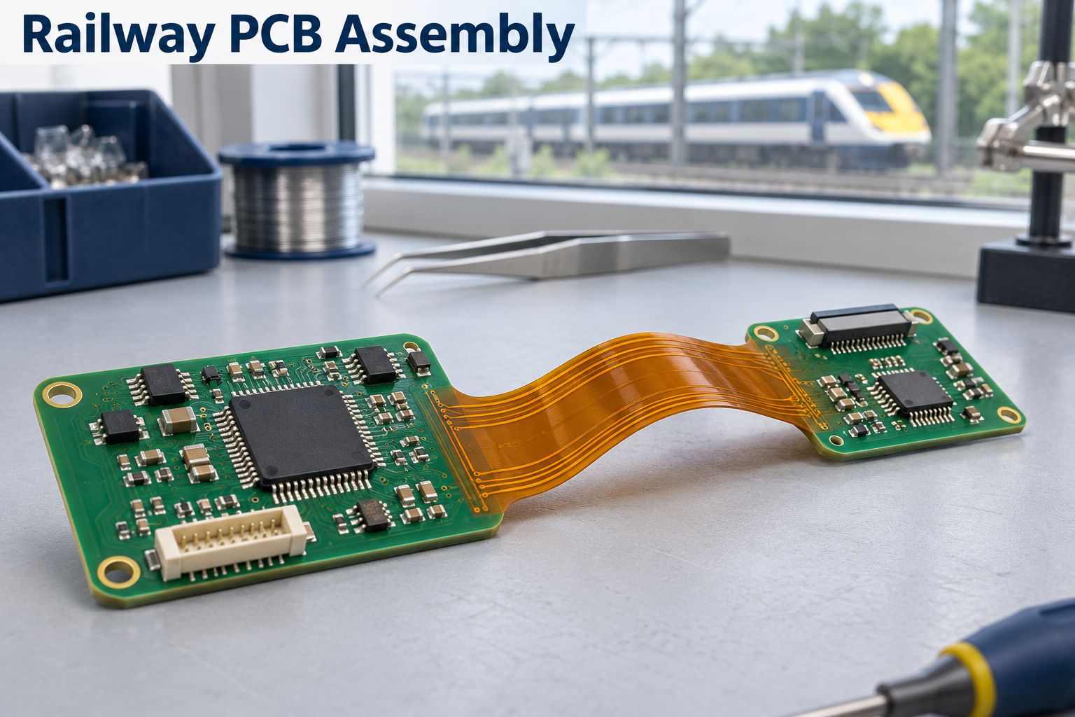
What Railway PCB Assembly Services Does BestFPC Provide?
We provide bare-board fabrication, component procurement and assembly for flexible and rigid-flex railway electronics. You can select a turnkey build, supply selected components, or provide the full component kit for assembly.
- Turnkey supply: We coordinate the circuit board, purchased components and assembly against one approved project package.
- Partial turnkey supply: You retain control of nominated or restricted parts while we purchase the remaining BOM items.
- Consigned assembly: We assemble customer-supplied parts after confirming quantities, packaging and identification.
Here, railway FPCBA means an assembled flexible printed circuit. A rigid-flex assembly combines rigid component-mounting regions with flexible interconnections. We establish the delivery scope at quotation so bare-board supply, assembled hardware and functional testing are priced and scheduled correctly.
What Are Our Railway FPCBA Manufacturing Capabilities?
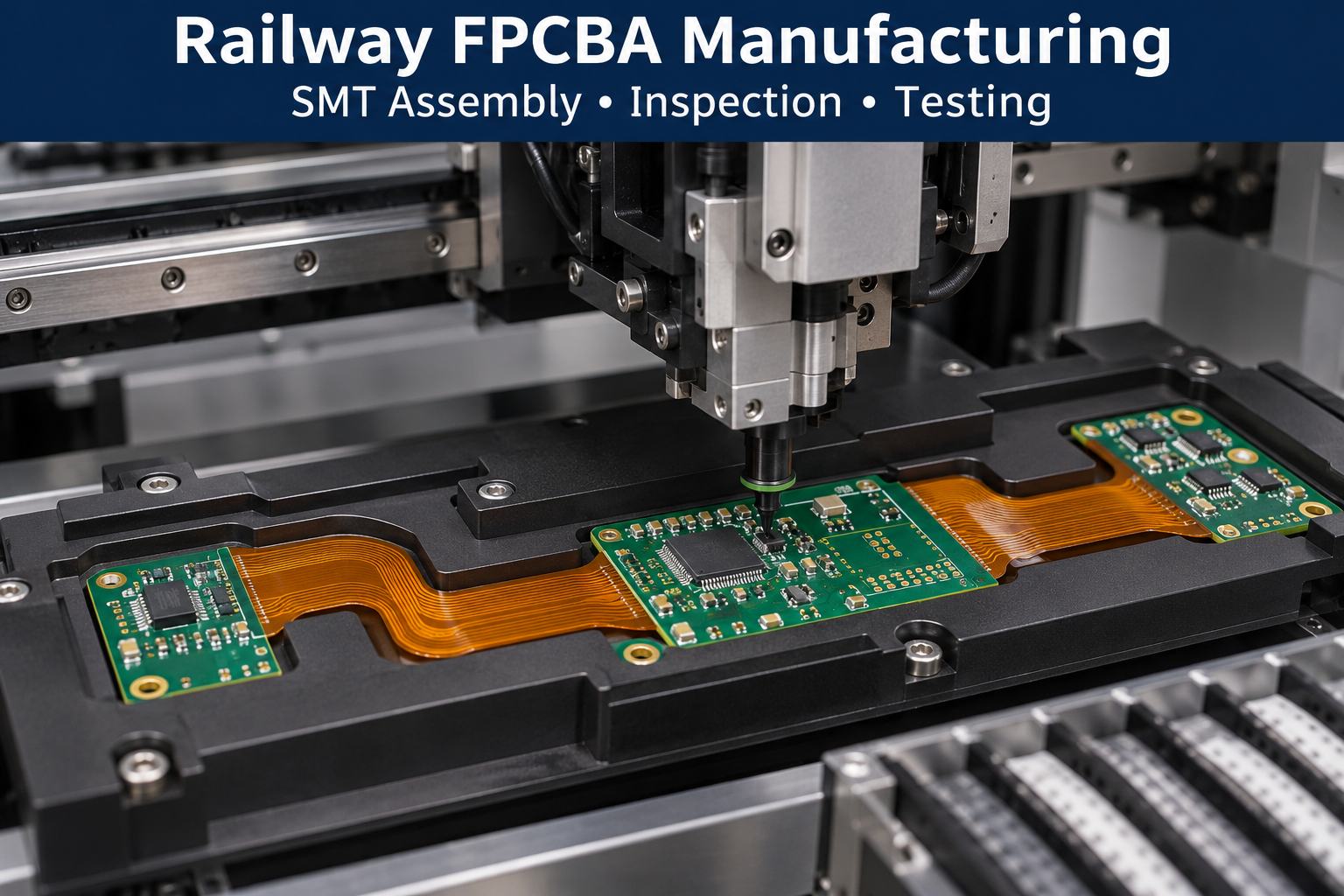
Our manufacturing scope includes flexible and rigid-flex circuits with SMT and through-hole assembly. The following capabilities help you assess the initial fit; the final combination depends on your stack-up, component layout and assembly route.
| Capability | Available range or process |
|---|---|
| Rigid-flex layer count | 2–20 layers |
| Rigid-flex finished thickness | 0.3–3.0 mm |
| Controlled-impedance tolerance | ±10% |
| Component mounting | SMT and through-hole |
| Minimum SMT package | 0201 |
| Maximum component size | 45 × 45 mm |
| Maximum placement height | 15 mm |
Layer count, thickness and impedance are board-fabrication capabilities. Component dimensions describe assembly equipment capability; they do not establish that every package can be mounted on an unsupported flex section. We confirm the material construction, local reinforcement and tooling together before releasing a build.
Inspection can include SPI, AOI, X-ray, ICT and functional testing. We select the applicable checks around the package types and agreed acceptance criteria; functional testing requires suitable instructions, access and test equipment.
How Do We Build Railway Rigid-Flex PCB Assembly for Control Equipment?
We start with the approved rigid-flex construction and define how the board will be supported through component placement, soldering and final installation. The main objective is to keep assembly loads away from flexible transitions while maintaining access to the required connections.
- Review the installed geometry. Identify mounting points, flex routing and connector locations so the assembly fixture does not conflict with the final shape.
- Plan component support. Check rigid mounting regions and reinforced areas for connector loading, component weight and soldering access.
- Define the assembly sequence. Coordinate SMT, through-hole work and any subsequent forming so handling does not place unnecessary strain on populated areas.
- Agree the release checks. Match inspection and electrical testing to the approved design before the build enters production.
For PCBA for railway control equipment, the complete installed drawing is as important as the flat board outline. It shows where the assembly must fit and which areas must remain free to bend.
Railway Communication PCB Assembly for Onboard Modules
We support railway communication PCB assembly on flexible and rigid-flex circuits, combining SMT placement, through-hole assembly and inspection for onboard modules. Our production resources cover prototypes, low-volume orders and mass production, with full turnkey, partial turnkey or customer-supplied components.
Assembly Capabilities
| Process item | Capability |
|---|---|
| Minimum SMT package | 0201 |
| Maximum component size | 45 × 45 mm |
| Maximum placement height | 15 mm |
| Mixed assembly | SMT + THT |
| BGA support | Inspection and rework |
| Post-assembly services | Product assembly, testing and aging |
For communication modules, these capabilities support the assembly of compact electronic components alongside larger interface components. We review connector orientation, flex-to-rigid transitions and mounting support against the installed drawing. Where controlled impedance is specified, the target values and stack-up remain part of the fabrication review.
Inspection and Testing
- First article inspection: Check the initial build before continuing with the production batch.
- SPI and online AOI: Inspect solder-paste deposition and visible placement or soldering features.
- X-ray inspection: Examine hidden solder joints where the package and inspection plan require it.
- ICT and functional testing: Check the agreed electrical and operating requirements using suitable fixtures, programming files and test instructions.
Production Resources
Our factory resources include more than 10 assembly lines, a stated SMT capacity of 19 million points per day and a placement-rate figure of 95,000 CPH. Through-hole resources include 50,000 insertion points and 20,000 post-soldering points per day. These are factory-level capacity figures; the output and schedule for a particular module depend on component count, process complexity and testing time.
How Do We Source Components for Railway FPCBA?
We review manufacturer part numbers, package details and availability before purchasing components for railway FPCBA. BOM optimization gives you specific purchasing decisions to resolve, rather than an unapproved substitution of cheaper parts.
- Incomplete descriptions: Flag missing manufacturer numbers or inconsistent package information before ordering.
- Availability concerns: Identify parts whose supply dates could determine the build schedule.
- Alternative components: Present candidates for customer approval, including differences that require engineering evaluation.
- Repeat-build changes: Recheck purchasing information when a new order or BOM revision is released.
A matching footprint does not make two parts interchangeable. Electrical ratings, operating conditions, firmware dependencies and approval requirements must also be considered. Your approved BOM remains the purchasing baseline.
What Certifications Do We Hold for Railway Flex PCB Assembly?
Our certifications include ISO 9001, ISO 13485, IATF 16949 and AS9100D, supporting quality management across several electronics applications:
- ISO 9001: General electronic products, including industrial control boards, communication modules and flexible circuit assemblies.
- ISO 13485: Medical electronics, such as monitoring devices, diagnostic equipment and medical FPC assemblies.
- IATF 16949: Automotive electronics, including control modules, sensor assemblies and vehicle interconnections.
- AS9100D: Aerospace electronics, including control, communication and instrumentation assemblies.
For railway flex PCB assembly projects, we provide the applicable certificates for review against the supplying facility and manufacturing scope. These are quality-system certifications, rather than approvals for individual railway products.
What Traceability Records Come with Railway FPCBA?
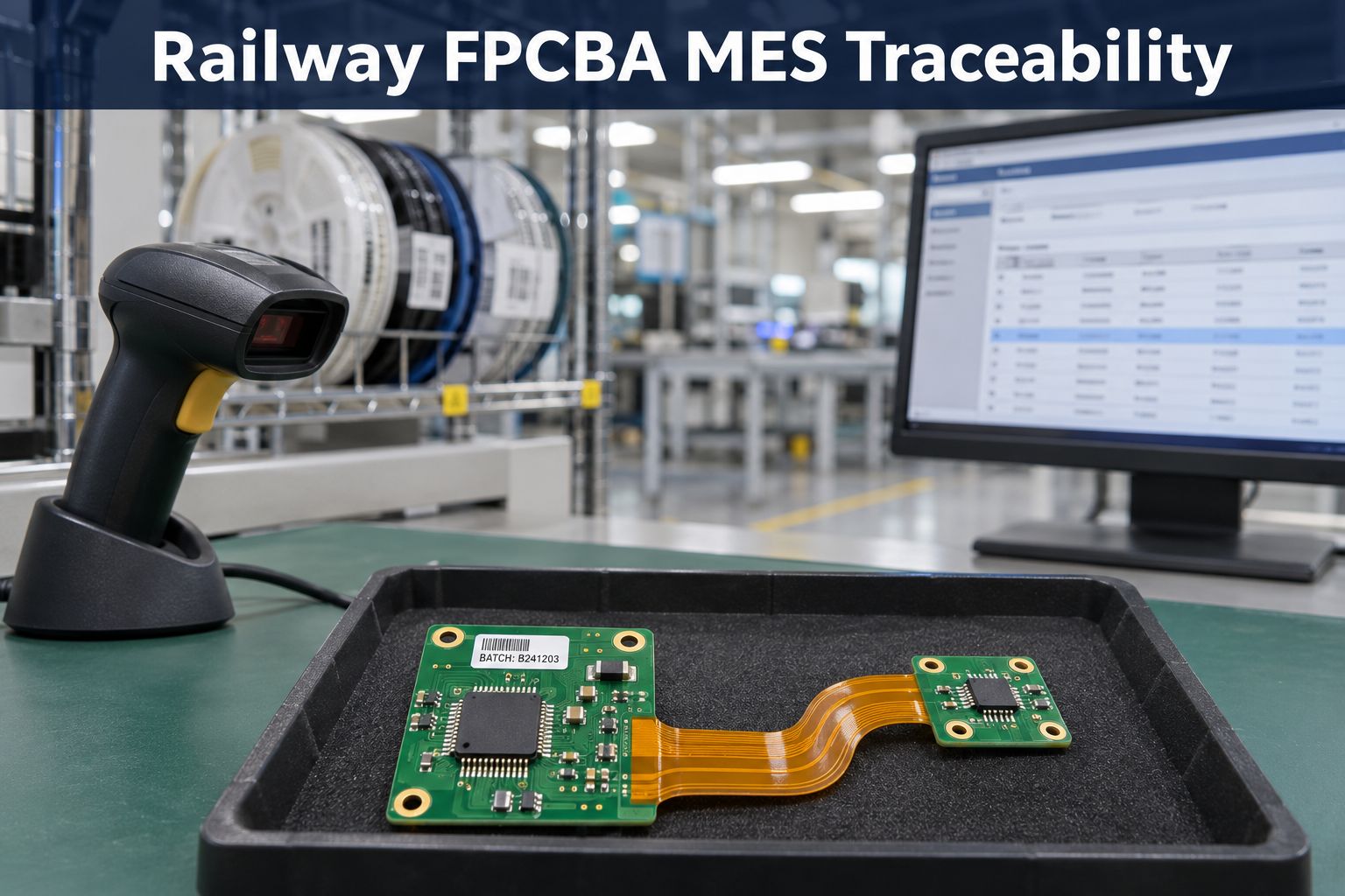
Our MES-based traceability helps connect railway FPCBA material batches, production progress and quality records. This gives your team a faster way to locate affected builds, investigate issues and review repeat orders.
- Batch lookup within 5 seconds: Our digital workshop can retrieve material and product-batch information within 5 seconds, reducing the time spent searching for production records.
- Targeted issue investigation: Batch links help identify which builds used a questioned material or component lot, so the investigation can focus on the relevant assemblies.
- Production progress visibility: Production-cycle and progress information helps our team identify where an order stands and provide clearer delivery updates.
- Build and inspection records: The agreed record package can include the released design revision, BOM, manufacturing work order and applicable inspection or test results, helping you review what was built and how it was checked.
- Shipment-batch identification: Linking production and shipment batches supports incoming inspection and later service investigations when a particular delivery needs to be traced.
We agree the record-delivery scope, retention period and any individual serialization requirements before production, so the traceability package matches your railway project's needs.
Can BestFPC Support Railway Flex PCB Assembly Prototypes?
Yes. We support prototype and small-batch railway flex PCB assembly so engineering teams can evaluate the proposed construction before a larger production release.
A useful prototype build should answer defined questions:
- Mechanical fit: Does the assembly fit its enclosure with the intended flex routing and connector orientation?
- Assembly feasibility: Can the populated regions be supported and handled through the planned production sequence?
- Test readiness: Are programming access, fixtures and acceptance instructions sufficient for repeatable checks?
After evaluation, approved changes should be incorporated into the next revision. Prototype acceptance establishes the agreed sample baseline; any wider railway equipment qualification remains a separate activity.
How Long Does Railway Rigid-Flex PCB Assembly Take?
Our fast-turn PCBA service can support eligible builds in approximately 1.5 weeks, subject to confirmed materials, released files, process requirements and test readiness. We confirm the applicable scope and delivery date for each railway rigid-flex PCB assembly quotation.
Three items commonly determine whether that route is practical:
- Board construction: A complex stack-up or material requiring procurement can extend fabrication preparation.
- Component readiness: A single unavailable critical part can hold up an otherwise ready build.
- Test preparation: New fixtures, programming instructions or unresolved acceptance criteria can delay release.
The quotation should state what the lead time includes and when it starts. Component procurement, engineering approval and shipping should not be assumed to fall inside the same manufacturing window.
Case Study: Rigid-Flex PCB for Subway Control
Application
BestFPC has delivered rigid-flex PCBs for subway internal-system control. For this application, an eight-layer rigid-flex construction offers rigid regions for mounting control electronics and flexible sections for routing connections within the equipment. The construction below illustrates a manufacturing option from our existing product range.
Manufacturing Challenges
- Different rigid and flex thicknesses: The 1.0 mm rigid region and 0.23 mm flexible section require distinct support during handling and assembly.
- Flexible interconnection: The flexible section must accommodate the installation route while keeping mounted parts and solder joints away from bending stress.
- Impedance requirements: The required signal layers and target values must be carried into the approved stack-up and fabrication instructions.
BestFPC Manufacturing Solutions
- Defined construction: Use TU-872 in the rigid region and the specified RA-copper flex construction, keeping the rigid and flexible thickness requirements separate.
- Supported assembly: Plan panel and fixture support around the populated regions, with the flex transitions protected during placement and soldering.
- Controlled fabrication inputs: Confirm the impedance details against the design files before production and retain the specified ENIG finish for component mounting.
Customer Benefits
The rigid regions provide stable mounting areas, while the thinner flex section gives the designer more freedom to connect board regions within the enclosure. A defined material and thickness specification also gives purchasing and engineering teams a consistent basis for quotation and repeat builds.
PCB Specifications
| Parameter | Selected board specification |
|---|---|
| Construction | 8-layer rigid-flex PCB |
| Rigid-region material | TU-872 |
| Rigid-region copper foil | 0.5 oz |
| Rigid-region thickness | 1.0 mm |
| Flex construction | 18/100/18 μm; RA copper |
| Coverlay thickness | 50 μm |
| Flex-region thickness | 0.23 mm |
| Surface finish | ENIG, 1 μin gold |
| Solder mask / legend | Green / white |
Why Choose BestFPC for Railway FPCBA?
BestFPC brings PCB fabrication, component sourcing and assembly resources together for railway FPCBA projects. The value is a manufacturing team that can address board construction and component purchasing within the same project.
- Experienced engineering team: Our team includes engineers with 20 years of experience, supported by PCB and PCBA engineering expertise for construction and process review.
- Specific engineering deliverables: DFM feedback and BOM optimization recommendations turn identified issues into actions you can approve before production.
- PCB and PCBA manufacturing resources: Our own manufacturing facilities and supplier network support coordinated purchasing and build planning.
- Quality-system documentation: We provide applicable certification documents for supplier qualification, with the relevant scope considered separately from product requirements.
- Prototype-to-production continuity: Samples and small batches allow changes to be resolved before repeat orders use the approved build configuration.
FAQs about Railway PCB Assembly
Can an NDA be agreed before design files are shared?
Yes. Send your confidentiality requirements first so an NDA can be agreed before you release sensitive design information.
Can bare boards and assembled boards be ordered separately?
Yes. Identify the quantities and delivery scope for each. Bare-board acceptance and assembled-board testing should be specified separately.
Does every railway PCB need the same certification?
No. Requirements depend on the equipment, installation and customer specification. Confirm the applicable standards and supplier qualifications at project review rather than applying one certificate to every railway board.
Can you assemble a replacement board for an existing fleet?
We can review a replacement-board project when the manufacturing files, BOM and acceptance requirements are available. An existing board or photograph alone does not establish a complete, approved replacement design.
What is needed for firmware programming and functional testing?
Provide the released firmware, programming method, test instructions and pass/fail criteria. Also identify any required fixtures, interface equipment or customer-supplied software access.
Is an installation bend the same as repeated flexing in service?
No. State whether the circuit is formed during installation or repeatedly moves during operation. That distinction belongs in the construction review and the customer's validation requirements.
With DFM feedback, BOM optimization and coordinated PCB-to-PCBA manufacturing, BestFPC helps turn railway circuit requirements into an actionable build plan. Send your Gerber files, BOM, placement data, installation drawing and quantities to sales@bestfpc.com so we can assess the construction, identify sourcing questions and prepare a quotation for your project.


.png)
.png)
.png)
.png)

.png)