


 2026-04-30
 BEST
BESTWhat Is a PET Flexible PCB — And Why It Matters for U.S. Engineers in 2026
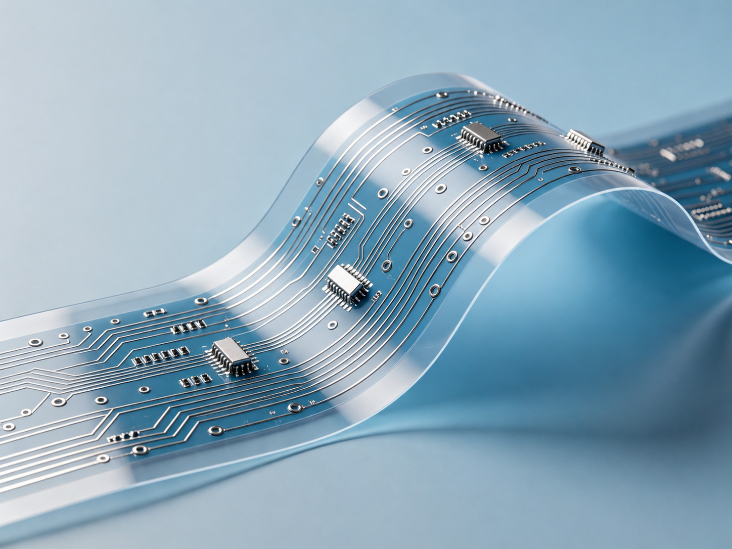
A PET flexible PCB is a transparent circuit board made of polyester material and flexible copper foil, with PET serving as the base, insulation, and coverlay material for the entire board. Unlike rigid circuit boards that restrict design geometry to flat planes, PET flexible PCBs bend, twist, and fold — enabling engineers to integrate electronic functionality into curved surfaces and confined spaces previously inaccessible to traditional PCB architectures.
The material science behind PET (polyethylene terephthalate) is well-established in the packaging and textile industries, but its emergence as a flexible circuit substrate represents a significant shift in how U.S. design engineers approach cost-constrained, high-volume electronics projects. PET offers a combination of properties that make it uniquely suited to specific application categories: transparency up to 85%, flexibility, lightweight construction, food safety, biosafety, and recyclability.
A PET flex PCB can accommodate 1 to 6 circuit layers depending on design complexity. However, it‘s crucial to understand that PET flexible PCBs can’t withstand high temperatures — their continuous operating range is typically -25°C to +75°C, and reflow soldering must be conducted at low temperatures below 150°C using specialized SnBi alloy solder paste with a 138°C melting point or conductive adhesive.
This temperature limitation is not a flaw — it's a design tradeoff that unlocks a 30-40% cost reduction compared to polyimide alternatives. For U.S. engineers developing consumer electronics, disposable medical sensors, RFID tags, membrane switches, and large-format antennas where thermal exposure is minimal, PET represents the economically rational substrate choice.
The global flexible PCB market was valued at approximately 24.57billionin2024andisprojectedtogrowataCAGRof7.324.57billionin2024andisprojectedtogrowataCAGRof7.343.98 billion by 2033. Within this expanding market, PET-based flex circuits are capturing an increasing share of consumer electronics, medical wearables, and IoT antenna applications — segments where cost efficiency and high-volume manufacturability outweigh extreme thermal performance requirements.
How PET Compares to Other Flexible Substrates at a Glance
The decision starts with material selection — and PET occupies a specific performance-cost position in the flex PCB substrate landscape.
| Material | Typical Thickness (μm) | Thermal Stability (°C) | Dielectric Constant (at 1 MHz) | Cost | Best Applications |
|---|---|---|---|---|---|
| Polyimide (PI) | 12.5–125 | Up to 400 (short-term) | 3.5 | High | Aerospace, Automotive, Industrial |
| PEN | 25–125 | Up to 180 (continuous) | 3.0 | Medium | Automotive Sensors, Moderate Heat |
| PET | 25–125 | Up to 150 (continuous) | 3.2 | Low | Consumer Electronics, Keypads |
The Engineering Transparency Advantage
PET flexible PCBs offer a transparency advantage that polyimide cannot match. PET materials are available in clear and white for flexible transparent PCBs, with no restriction on colors. Transparent PET flex PCBs are widely used in automotive lights, glass light walls, LED displays, wearables, biological lab equipment, and even subdermal animal trackers.
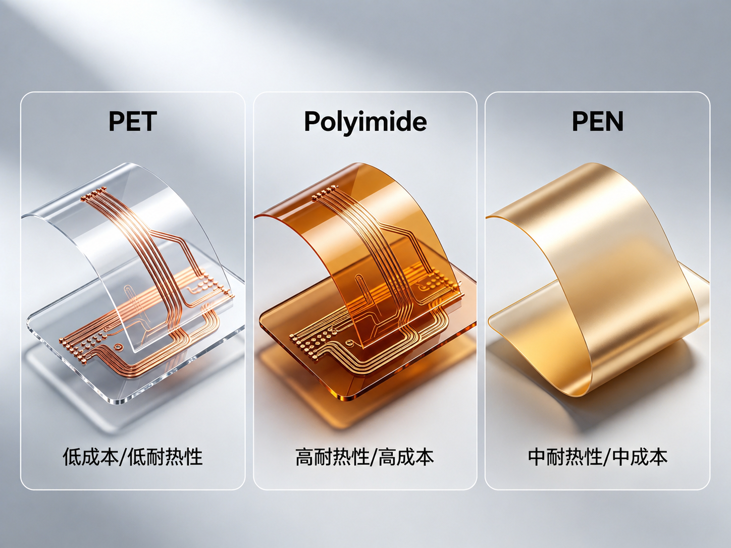
PET vs. Polyimide vs. PEN: The Ultimate Flex PCB Material Showdown
Selecting between PET, polyimide, and PEN is arguably the single most consequential decision in a flexible circuit design project. The wrong material choice locks in performance limitations that no amount of clever routing can overcome.
Polyimide dominates the flex PCB market with approximately 85% share of all flexible circuit substrates, primarily due to its exceptional thermal stability, mechanical durability, and ability to withstand lead-free reflow soldering at 260°C peak temperatures. But that dominance comes at a price — literally. A polyimide substrate costs 3-5x more than PET.
PEN occupies a middle ground between PET and PI. It offers better thermal performance than PET at approximately 180°C, while costing less than polyimide. For applications that demand more durability than PET can offer but don‘t require the full capabilities of polyimide, PEN is a solid intermediate choice.
Polyimide — When High Performance Is Non-Negotiable
Polyimide, developed by DuPont as Kapton in the 1960s, delivers an exceptional combination of thermal resistance, chemical stability, and mechanical durability. Its key specifications include a glass transition temperature (Tg) of 360-410°C, continuous operating range of -269°C to 260°C, dielectric constant (Dk) of 3.2-3.5 at 1 GHz, moisture absorption of 1.5-3.0%, and a dynamic bend cycle life exceeding 100,000 cycles with UL 94 V-0 flammability rating.
Polyimide is the right choice for applications involving soldering (withstands lead-free reflow temperatures at 260°C peak without deformation), dynamic flexing (applications requiring repeated bending over the product lifetime such as printer heads and foldable displays), high-reliability environments (aerospace, automotive, and medical devices where failure is not an option), and multilayer flex constructions with 4+ layers where thermal stability during lamination is critical.
PET — The Cost-Effective Workhorse
PET flexible PCBs cost approximately 30-40% less than polyimide options. PET also handles sweat and moisture well, weighs very little, and offers transparency. However, PET’s thermal ceiling of approximately 150°C disqualifies it from applications requiring standard lead-free reflow soldering. PET flex PCBs cant be soldered by wave soldering but only by low-temperature reflow soldering below 150°C.
A critical engineering note: PET flex PCBs dont have traditional plated through holes (PTH) but use non-plated through holes (NPTH). If a through hole needs to be conductive, it is filled with silver, carbon ink, or conductive adhesive. The surface finish for PET flexible PCB SMT soldering is OSP or ENIG — silver plating is not recommended because silver ions diffuse easily in PET.
PEN — Bridging the Gap
PEN provides a maximum operation temperature of up to 135°C with high short-term temperature resistance that offers brazeability. Both PET and PEN have a white appearance, absorb little moisture, and are perfect for humidity-exposed installation spaces. For U.S. engineers who need slightly more thermal headroom than PET can deliver but cannot justify the cost premium of polyimide, PEN represents an underutilized middle path.
When to Choose PET — A Decision Checklist
Consider PET for your design if the following conditions are met:
- Your circuit’s peak operating temperature stays below 105°C. PET features a maximum operation temperature of up to 105°C.
- Your design does not require dynamic, high-cycle-count flexing.
- Cost-per-unit is a primary design constraint, particularly for high-volume consumer products.
- You are building large-format circuits such as antennas where PET‘s low cost makes it the first choice.
- You need transparency for optical applications such as LED lighting or lab equipment.
- Your assembly process accommodates low-temperature reflow or uses ZIF connectors for component attachment.
7 Critical Decision Factors U.S. Engineers and Procurement Teams Use to Select PET Flexible PCB Suppliers
Selecting a PET flexible PCB supplier is fundamentally different from sourcing rigid PCBs. The material’s unique thermal constraints, processing requirements, and application-specific performance characteristics demand a more nuanced evaluation framework. Based on analysis of U.S. procurement patterns across consumer electronics, medical device, and IoT sectors, here are the seven decision factors that consistently rank highest — with specific PET-centric considerations that generic supplier evaluations often miss.
Factor 1 — PET Material Expertise and Substrate Inventory
Not all PET films are equal. The quality, thickness consistency, and optical clarity of the PET substrate directly affect circuit yield, bend performance, and transparency. A qualified PET flex PCB supplier should maintain relationships with multiple PET film manufacturers, offer various thickness options (typically 25-125 μm), and provide material traceability documentation.
Engineers should ask: Does the supplier stock multiple PET grades? Can they provide PET films with specific optical properties (clear, white, or tinted)? Do they understand the hydrolytic stability characteristics of different PET formulations?
BESTFPC has extensive experience working with PET material PCBs, offering cost-effective options with excellent flexibility across a range of thickness specifications.
Factor 2 — Low-Temperature Assembly Process Expertise
PET flexible PCBs cannot survive standard lead-free reflow soldering profiles. This creates a critical process requirement: the supplier must demonstrate expertise in low-temperature assembly methodologies, including SnBi alloy soldering (138°C melting point), conductive adhesive attachment, and ZIF connector-based interconnection strategies.
A PET flex PCB supplier without this low-temperature process expertise represents a significant reliability risk. Ask suppliers for documentation of their low-temperature solder profiles, evidence of joint reliability testing, and references from customers who have successfully deployed PET flex circuits in volume.
Factor 3 — Quality Certifications and Process Standards
Quality certifications are the baseline filter for any flex PCB supplier serving the U.S. market. For PET flexible PCBs specifically, the certification stack should include ISO 9001 quality management, UL recognition for material safety, IPC-6013 qualification and performance specification compliance, RoHS compliance verification, and IPC-A-600 visual acceptability standards.
IPC-6013 affects PET flex PCB cost, lead time, incoming inspection, and field risk. Buyers should specify the appropriate IPC performance class and request test evidence, including coverlay adhesion results, conductor integrity documentation, and plating quality verification . BESTFPC uses IPC-6013 Class 3 rules to ensure flex circuits meet the highest quality and reliability standards, with careful material selection and testing protocols designed for demanding environments .
Factor 4 — NPTH and Via-Fill Capability
PET flex PCBs don’t use traditional plated through holes — a design reality that creates specific fabrication requirements. The supplier must demonstrate competence in non-plated through hole (NPTH) formation, conductive via filling using silver paste, carbon ink, or conductive adhesive, and clean, precise hole formation without substrate damage .
Most rigid PCB fabricators lack this NPTH and conductive-fill expertise because their processes are built around traditional electroless copper plating. When evaluating a PET flex PCB supplier, request cross-section micrographs of filled vias and inquire about their conductive fill material options, resistance specifications, and long-term reliability data.
Factor 5 — Panel Utilization and High-Volume Efficiency
PET flexible PCBs are frequently used in high-volume consumer applications where per-unit cost is a dominant design constraint. Panel utilization efficiency — the percentage of the fabrication panel that yields deliverable circuits — directly impacts unit cost. Suppliers who can optimize panel layouts to maximize utilization, and who operate large-format processing equipment suited to PET’s cost advantages, deliver meaningful per-unit savings at volume.
BESTFPC provides flexible circuit solutions optimized for small-batch, multi-class, high-quality, on-time delivery across various application formats. This production flexibility enables U.S. buyers to transition smoothly from prototype validation to pilot production and full-volume ramp-up without changing suppliers or re-qualifying processes .
Factor 6 — Engineering Support and Design-for-Manufacturability
PET flexible PCB designs present unique DFM challenges that require specialized expertise: bend radius calculations accounting for PET‘s specific mechanical properties, temperature management to ensure the circuit operates within PET’s thermal envelope, connector and stiffener integration strategies, and proper pad and surface finish selection for low-temperature assembly.
A qualified supplier should review FPC/PCB designs before production, flag potential issues (such as flex zones with too-tight bend radii that would cause cracks), and suggest fixes that prevent costly redesigns later . Request sample DFM reports during the supplier evaluation process to assess the depth and quality of their engineering engagement.
Factor 7 — Total Cost of Ownership and Transparent Pricing
The sticker price of a PET flex PCB quotation tells only part of the story. U.S. procurement teams evaluate total cost of ownership, which encompasses unit fabrication cost, tooling and non-recurring engineering charges, scrap and rework costs from quality issues, logistics and tariff exposure, inventory carrying costs, and engineering time spent managing supplier quality problems.
A supplier with robust PET-specific quality processes — including proper surface finish selection (OSP or ENIG recommended; silver plating avoided due to silver ion diffusion), appropriate solder paste specification (SnBi alloy with 138°C melting point), and thorough electrical testing protocols — often delivers superior TCO despite a nominally higher unit price . Ask potential suppliers for first-pass yield data, on-time delivery performance metrics, and corrective action closure rates specific to their PET flex PCB production lines.
BESTFPC’s vertically integrated manufacturing model — with in-house control over all critical process steps — provides U.S. customers with the tight quality control, faster lead times, and clear accountability that sophisticated procurement teams demand. The company maintains ISO, IATF, SGS, and UL certifications, with applications expertise spanning medical, automotive, industrial, and consumer electronics markets .
PET Flexible PCB Manufacturing Process — From Substrate to Finished Circuit
Understanding the PET flex PCB fabrication process helps U.S. engineers write better specifications, anticipate manufacturing constraints, and effectively evaluate supplier capabilities during the sourcing phase.
Step 1 — PET Substrate Preparation
The process begins with high-quality PET film selected for the appropriate thickness, optical properties, and dimensional stability requirements of the application. PET films are available in thicknesses ranging from 25 μm to 125 μm . The film is inspected for surface defects, thickness consistency, and contamination before processing.
Step 2 — Copper Lamination
Copper foil is bonded to the PET substrate through an adhesive lamination process. For PET flex circuits, the adhesive selection is critical — it must maintain flexibility, withstand the circuit‘s operating temperature range, and provide reliable copper adhesion without degrading over time. The lamination process parameters (temperature, pressure, dwell time) are specifically adjusted for PET’s thermal sensitivity.
Step 3 — Circuit Patterning and Etching
A photolithographic process defines the circuit pattern. Photosensitive dry film is applied, exposed through a photomask, and developed. The exposed copper is etched away using an alkaline solution, leaving behind the precise circuit traces. Tight process control is essential to achieve fine-line definition without damaging the thin PET substrate.
Step 4 — Via Formation and Conductive Filling
Since PET cannot undergo traditional electroless copper plating for plated through holes, vias are formed through mechanical drilling or laser processing as non-plated through holes (NPTH). Where electrical interconnection between layers is required, vias are filled with conductive silver paste, carbon ink, or conductive adhesive — materials specifically selected for compatibility with PET’s surface chemistry and thermal limits .
Step 5 — Coverlay or Insulation Layer Application
A PET-based coverlay or insulation layer is applied over the copper traces to provide electrical insulation, mechanical protection, and environmental resistance. For transparent PET flex circuits, the coverlay must maintain optical clarity while providing adequate circuit protection.
Step 6 — Surface Finish Application
Surface finish options for PET flexible PCBs include OSP (Organic Solderability Preservative) and ENIG (Electroless Nickel Immersion Gold). Silver plating is not recommended because silver ions diffuse easily in PET, potentially causing electrical leakage or reliability issues . The surface finish selection must be compatible with the planned low-temperature assembly process.
Step 7 — Electrical Testing, Profiling, and Final Inspection
Each PET flex circuit undergoes electrical testing to verify continuity, isolation, and impedance conformance. The circuit is then profiled — typically through laser cutting or die-cutting — to its finished outline. Final inspection includes visual examination under magnification and, when specified, cross-section analysis to verify internal layer integrity.
BESTFPC’s facility operates with 200+ staff and complete in-house capability for all process steps, delivering PET flex PCBs with consistent quality from prototype through production volumes.
PET Flexible PCB Cost Drivers — How to Optimize Your Flex Circuit Budget
Material selection constitutes 25-40% of total PCB manufacturing costs, and for PET flexible PCBs, understanding the cost structure is essential for accurate budgeting and value engineering .
The PET Cost Advantage Quantified
PET offers the most compelling cost profile among flex PCB substrate options. The base material cost comparison is striking: PET film is approximately 5x less expensive than polyimide film per square meter, with PET priced around ¥10/m² compared to polyimide’s ¥30/m² . When translated to finished circuit costs, PET flex PCBs are typically 30-40% cheaper than equivalent polyimide designs .
Compared to rigid PCBs for context, PET costs roughly 1.5x a rigid PCB versus polyimide’s 4x premium . This positions PET as the closest flexible alternative to rigid PCB pricing while still offering the mechanical benefits of a flexible substrate.
Cost Structure Breakdown for PET Flexible PCBs
Material Costs (25-40% of total): The PET substrate, copper foil, adhesive layers, coverlay film, and surface finish materials. While PET substrate cost is low, copper thickness selection and coverlay specifications can significantly shift material costs.
Layer Count Impact: A 2-layer PET flex PCB is approximately 50% more expensive than a single-layer configuration . Each additional layer adds lamination cycles, registration complexity, and yield challenges.
Surface Finish Selection: ENIG typically commands a premium over OSP, though ENIG offers superior shelf life and flatness for fine-pitch component attachment.
Via Fill Requirements: Conductive via filling using silver paste adds material and processing costs compared to simple NPTH designs.
Panel Utilization: Efficient nesting of circuit outlines on the fabrication panel minimizes material waste and reduces unit cost. Irregular board shapes and non-standard dimensions can significantly degrade panel utilization.
Cost Optimization Strategies for U.S. Buyers
- Engage DFM support early. Early design review with PET-specific DFM feedback can eliminate cost-prohibitive features before design lock.
- Standardize material callouts. Specifying commonly stocked PET thicknesses and copper weights avoids custom procurement charges.
- Minimize layer count. Evaluate whether design requirements genuinely justify additional layers.
- Consider NPTH-only designs. Eliminating conductive via fill requirements where possible reduces processing cost.
- Optimize panelization. Work with your supplier to adjust outline dimensions for maximum panel utilization.
- Plan volumes strategically. Prototype quantities carry significant per-unit premiums; consolidating builds across multiple designs can unlock volume pricing.
PET Flex PCB Cost Ranges (Benchmark Estimates — U.S. Market 2026)
| Volume | 2-Layer PET Flex | 4-Layer PET Flex |
|---|---|---|
| Prototype (5–20 pcs) | $40–120/board | $80–250/board |
| Pilot (50–500 pcs) | $8–25/board | $18–60/board |
| Volume (1,000–10,000+ pcs) | $2–7/board | $5–18/board |
Ranges vary based on size, design complexity, panel utilization, and surface finish specification. Request formal quotations for project-specific pricing.
Internal linking tip: For readers comparing advanced material options, see our related analysis on PET Flexible PCBs Compared with Other Leading Materials for a comprehensive comparison of PET, polyimide, and PEN substrate performance across key engineering parameters, including thermal stability, dielectric constant, and cost-per-unit-area benchmarks that directly inform material selection decisions .
Where PET Flexible PCBs Win — Real-World U.S. Application Case Studies
PET flexible PCBs have carved out specific application domains where their unique combination of low cost, transparency, and adequate flexibility delivers compelling design advantages. Understanding these application patterns helps U.S. engineers identify whether PET is the right material choice for their specific project.
Large-Format Antennas and RF Applications
PET is the most cost-efficient base material for large-format Flexible Printed Circuit boards, with lowest costs making it the first choice for large-format applications such as antennas . FPC antennas can be manufactured on PET substrates, utilizing the material‘s low dielectric constant of approximately 3.2 to support efficient RF performance in cost-sensitive wireless products including 5G-enabled smartphones, foldable devices, smartwatches with embedded antennas, wearable fitness trackers, Bluetooth headsets, and IoT sensor applications .
LED Lighting and Transparent Display Applications
PET’s transparency — up to 85% light transmission — makes it the preferred substrate for transparent flexible circuits used in automotive lighting, glass wall displays, LED arrays, and architectural lighting applications . The combination of optical clarity, flexibility, and low cost creates design possibilities unavailable with opaque polyimide substrates.
Consumer Electronics and Membrane Switches
Consumer electronics represent PET‘s highest-volume application category. PET flex PCBs serve in membrane switches, keypads, remote controls, and low-cost sensor interconnects where the operating environment stays well within PET’s thermal and mechanical limits .
Disposable Medical Sensors and Wearable Patches
The medical wearables sector is emerging as a significant growth driver for PET flexible PCBs. PET‘s biocompatibility, low cost (enabling disposable use cases), and moisture resistance make it ideal for single-use medical patches, biosensor arrays, and patient monitoring devices that require flexibility and skin-safe materials without the cost premium of polyimide.
RFID Tags and Smart Labels
PET-based RFID antennas and smart labels benefit from the substrate’s low cost, adequate RF performance, and compatibility with high-volume roll-to-roll manufacturing processes. The material‘s recyclability and food-safety characteristics also support applications in food packaging and retail environments .
Internal linking tip: For a deeper technical understanding of flexible circuit material options, explore our comprehensive guide to flexible PCB materials covering substrate properties, conductive layer selection, adhesive systems, and coverlay technologies with detailed property comparison tables — essential reading for engineers making material decisions .
Tariffs, Lead Times, and Sourcing PET Flex PCBs into the U.S. Market
U.S. procurement teams evaluating PET flexible PCB sourcing options in 2026 must navigate a dynamic landscape of tariffs, lead times, and logistics costs.
U.S. Tariff Impact on PET Flexible PCB Imports (2026 Update)
As of early 2026, flex and rigid-flex PCBs from China face Section 301 tariffs of 25% on top of standard Most-Favored-Nation rates, plus additional IEEPA tariffs of 10% — resulting in a total effective tariff rate of approximately 35% for flex PCBs from certain manufacturing origins. However, Section 301 tariff exclusions have been extended through November 2026 for qualifying PCBs, which may reduce exposure for specific import classifications. U.S. buyers should verify their flex PCB import classifications and factor total landed cost into supplier comparison models.
PET Flex PCB Lead Time Benchmarks
Lead time expectations for PET flexible PCBs vary significantly by supplier location and production capacity:
- U.S. Domestic Prototypes: 5 working days for standard single-sided and double-sided designs
- Offshore Prototypes: 7-15 working days for standard complexity
- U.S. Domestic Volume Production: 2-4 weeks
- Offshore Volume Production: 2-5 weeks
For high-layer-count PET flex PCBs (4-6 layers) or designs requiring specialized conductive via filling, add 3-7 days to standard lead time estimates.
Comparing Domestic vs. Offshore PET Flex PCB Sourcing
Domestic U.S. manufacturing offers faster turnaround, easier communication, and stronger IP protection — but at significantly higher unit costs. Offshore manufacturing delivers lower per-unit pricing due to labor and material cost advantages, though with longer logistics timelines and tariff exposure. The optimal sourcing strategy for many U.S. buyers is a hybrid approach: domestic for prototyping and IP-sensitive designs, offshore for cost-optimized volume production.
BESTFPC bridges this gap effectively by offering competitive lead times for both prototype and volume orders through its 3,000㎡ facility with 200+ staff, providing the quality certifications (ISO, IATF, SGS, UL) and responsive customer support that U.S. procurement teams require while maintaining the cost advantages of offshore production .
Why U.S. Engineering Teams Are Partnering with BESTFPC for PET Flexible PCB Projects
Throughout this guide, we have examined the technical and commercial factors that U.S. engineers weigh when selecting a PET flexible PCB supplier. BESTFPC‘s value proposition aligns with each evaluation dimension in ways that directly serve the needs of cost-conscious, quality-focused U.S. buyers.
Established PET Material Expertise
BESTFPC has documented expertise in PET material PCB manufacturing, with published technical content covering PET’s cost-effectiveness, flexibility characteristics, thickness ranges, and application suitability compared to polyimide and PEN alternatives . This material knowledge translates into practical DFM guidance for U.S. engineers specifying PET flex circuits.
Comprehensive Certification Portfolio
BESTFPC maintains ISO, IATF, SGS, and UL certifications, uses IPC-6013 Class 3 rules to ensure flex circuit quality and reliability, and operates with careful material selection and testing protocols designed for demanding environments . For U.S. buyers in regulated industries, this certification foundation is a non-negotiable prerequisite.
Vertically Integrated Manufacturing
With a 3,000㎡ facility, 200+ staff, and complete in-house production capability, BESTFPC delivers the tighter quality control, faster lead times, and clear accountability that come from owning every process step — from material preparation through electrical testing and final inspection. No critical processes are outsourced.
Flexible Volume Support Across the Product Lifecycle
Whether you need prototype quantities (5-50 pieces) for engineering validation, pilot production (50-500 pieces) for design verification, or volume manufacturing (1,000-10,000+ pieces) for commercial ramp-up, BESTFPC‘s small-batch, multi-class production model scales with your project.
Proven Track Record with U.S. and Global Customers
BESTFPC serves customer industries including automotive, medical, industrial, consumer electronics, and emerging markets, with medical and smart wearable devices accounting for approximately 80% of export volume. The company specializes in flex circuits, offering a wide range of products including rigid-flex circuits and multi-layer flex circuits with comprehensive services such as component purchasing, assembly, IC programming, and testing .
Frequently Asked Questions About PET Flexible PCB
Q1: What is a PET flexible PCB and how does it differ from polyimide flex PCB?
A PET flexible PCB uses polyethylene terephthalate (polyester) as the substrate material rather than polyimide. PET costs approximately 30-40% less than polyimide, offers transparency up to 85%, and provides good moisture resistance — but its maximum operating temperature is limited to approximately 105-150°C compared to polyimide’s 260-400°C range. PET flex PCBs require low-temperature assembly processes (below 150°C) using specialized SnBi solder paste or conductive adhesive, and they use non-plated through holes (NPTH) rather than traditional plated through holes.
Q2: What are the temperature limits of PET flexible PCBs?
PET flexible PCBs have a continuous operating temperature range of approximately -25°C to +75°C, with a maximum short-term temperature tolerance of up to 150°C. Reflow soldering must be performed at temperatures below 150°C using low-temperature solder paste (typically SnBi alloy with a 138°C melting point) or conductive adhesive. PET flex PCBs cannot withstand standard lead-free reflow profiles that peak at 260°C.
Q3: How much do PET flexible PCBs cost compared to polyimide?
PET flexible PCBs typically cost 30-40% less than equivalent polyimide flex circuits. On a material cost basis, PET film costs approximately ¥10/m² compared to polyimide‘s ¥30/m². Compared to rigid PCBs, PET flex costs roughly 1.5x while polyimide flex costs approximately 4x. For volume production, a 2-layer PET flex PCB typically ranges from 2−7perboardatquantitiesof1,000+,whileequivalentpolyimidedesignsrangefrom2−7perboardatquantitiesof1,000+,whileequivalentpolyimidedesignsrangefrom5-18 per board.
Q4: What are the most common applications for PET flexible PCBs?
PET flexible PCBs are most commonly used in large-format antennas, consumer electronics (membrane switches, keypads, remote controls), LED lighting and transparent displays, disposable medical sensors and wearable patches, RFID tags and smart labels, and biological lab equipment. PET’s transparency, low cost, and biocompatibility make it particularly well-suited for optical and disposable applications.
Q5: Can PET flexible PCBs have plated through holes?
No — PET flexible PCBs do not have traditional plated through holes (PTH). They use non-plated through holes (NPTH) instead. If a through hole needs to be electrically conductive, it is filled with silver paste, carbon ink, or conductive adhesive rather than being plated with electroless copper.
Q6: What surface finishes work with PET flexible PCBs?
The recommended surface finishes for PET flexible PCBs are OSP (Organic Solderability Preservative) and ENIG (Electroless Nickel Immersion Gold). Silver plating is not recommended because silver ions diffuse easily in PET material, potentially causing reliability issues. For designs with conductive button contacts rather than soldered connections, carbon ink can be used as the surface finish.
Q7: How transparent are PET flexible PCBs?
PET flexible PCBs can achieve transparency up to 85% light transmission. PET materials are available in clear, white, light green, and light blue variants. The transparency advantage makes PET flex PCBs particularly suitable for LED lighting, glass wall displays, automotive lighting, and optical lab equipment where polyimide’s characteristic amber color is aesthetically or functionally unacceptable.
Q8: What certifications should a PET flexible PCB supplier have?
A qualified PET flex PCB supplier should hold ISO 9001 quality management certification, UL recognition for material safety, compliance with IPC-6013 qualification and performance specifications, and RoHS compliance verification. For medical device applications, ISO 13485 is recommended. For automotive, IATF 16949 is increasingly mandatory. Always verify current certification status — do not accept claims without supporting documentation.
Q9: What is the typical lead time for PET flexible PCB fabrication?
Prototype lead times typically range from 5 to 12 working days for standard single-sided and double-sided PET flex circuits. Multilayer PET flex PCB prototypes (4-6 layers) generally require 10 to 18 working days. Volume production cycles range from 2 to 5 weeks depending on complexity, order quantity, and supplier capacity.
Q10: How do U.S. tariffs affect PET flexible PCB pricing from overseas suppliers?
As of 2026, flex and rigid-flex PCBs imported from China face a total effective tariff rate of approximately 35% (Section 301 tariffs of 25% plus IEEPA tariffs of 10%), though Section 301 tariff exclusions extended through November 2026 may reduce exposure for qualifying import classifications. U.S. buyers should factor total landed cost — including tariffs, logistics, and brokerage — into supplier comparisons and verify HTS code eligibility for any active exclusion programs.
This guide was last updated: April 2026. For current PET flexible PCB quotations, design support, or to discuss your specific project requirements, visit www.bestfpc.com or contact the BESTFPC engineering team directly.
.png)
.png)
.png)
.png)

.png)

