


 2026-04-29
 BEST
BESTThe 2026 U.S. Flex PCB Market Landscape — Why Fabrication Demand Is Surging
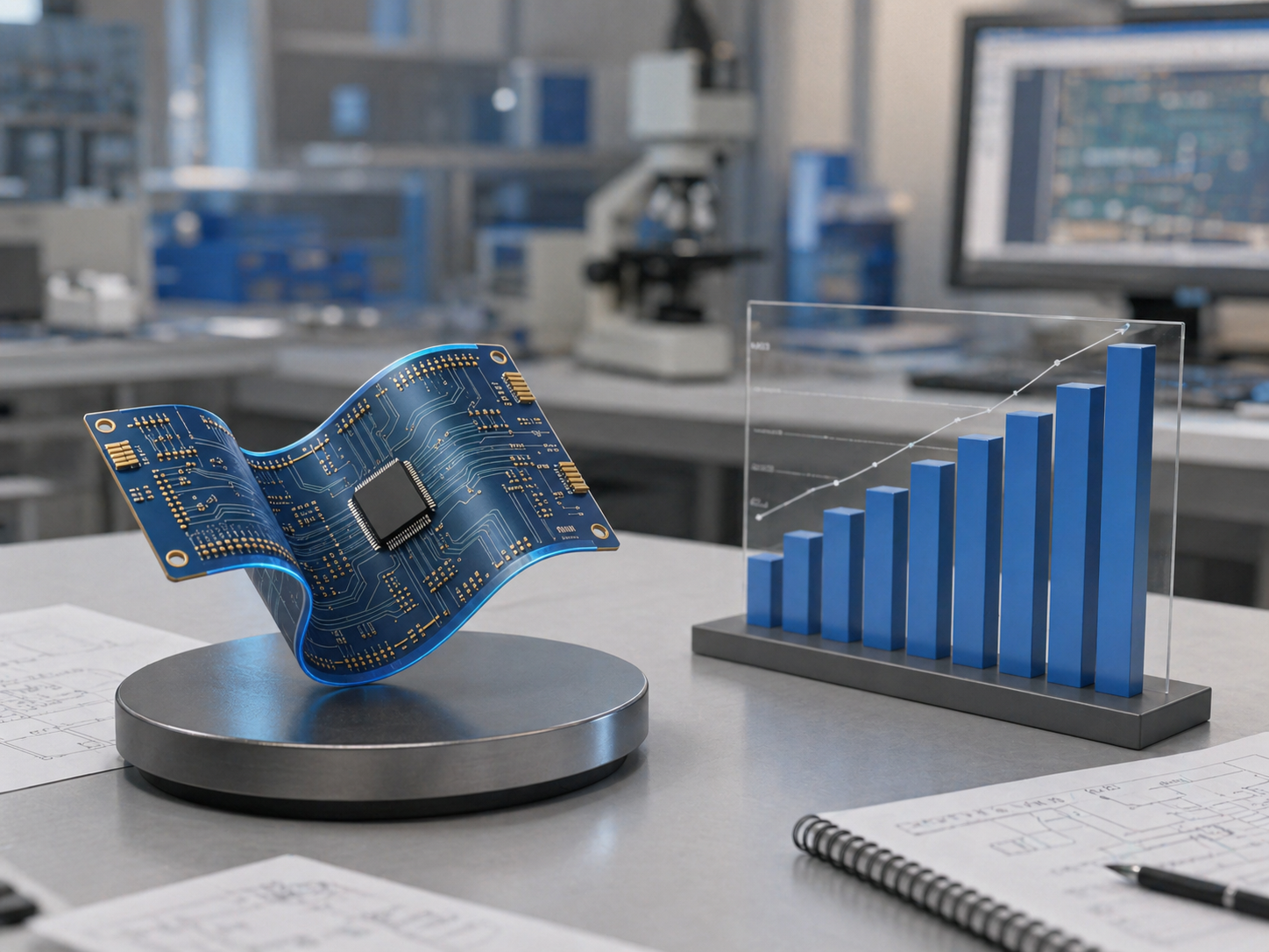
The flexible printed circuit board market is experiencing one of the most significant growth trajectories in the electronics manufacturing sector. The North American flexible PCB market was valued at approximately 1.7billionin2025andisprojectedtoreach1.7billionin2025andisprojectedtoreach2.9 billion by 2030, growing at a compound annual growth rate (CAGR) of 10.9%. On a global scale, the market is expected to expand from 28.36billionin2025to28.36billionin2025to31.07 billion in 2026 alone, reflecting a 9.5% year-over-year growth rate driven by mobile device manufacturing, demand for lightweight circuit solutions, and telecommunications infrastructure expansion. Looking further ahead, the global flexible PCB market could reach $41.7 billion by 2030, with a CAGR of 12.3% fueled by consumer electronics, electric vehicles, and 5G infrastructure demands.
U.S. engineers and procurement professionals are at the center of this expansion. Several converging trends make flex PCB fabrication a strategic priority: the continued miniaturization of medical devices and wearables, the electrification of automotive platforms requiring high-reliability interconnects in confined spaces, the rollout of 5G and advanced communication systems, and the growing adoption of rigid-flex architectures in aerospace and defense applications. These applications demand fabrication partners who understand not just how to manufacture flexible circuits, but how to do so with the precision, consistency, and compliance that mission-critical U.S. industries require. This means buyers are scrutinizing fabrication capabilities more rigorously than ever before — and for good reason.
Why U.S. Procurement Teams Are Rethinking Their Flex PCB Fabrication Strategy
The traditional sourcing model — evaluating suppliers solely on unit price — is being replaced by a more sophisticated total-cost-of-ownership approach. U.S. procurement teams now weigh fabrication quality, certification rigor, engineering support, supply chain stability, and long-term partnership viability alongside unit economics. The best supplier is not simply the lowest quote; it is the one that can build flex circuits reliably, repeatably, and efficiently, with strong design-for-manufacturability (DFM) support and stable process control.
Supply Chain Resilience as a Competitive Advantage in Flex PCB Fabrication
The most forward-thinking U.S. buyers are building supplier ecosystems that combine the speed and IP protection advantages of domestic manufacturers with the scalability and cost efficiencies of qualified offshore partners. This hybrid approach — sometimes termed "nearshoring plus" — is increasingly common in medical device, automotive, and industrial sectors where both agility and margin matter. For companies that demand uncompromising quality, Best Technology (BESTFPC) delivers flexible circuits backed by 20 years of ISO, IATF, SGS, and UL certifications.
What Is Flex PCB Fabrication? A Technical Deep Dive for Engineering Professionals
Flex PCB fabrication is the complete manufacturing process that transforms raw materials — primarily polyimide films and copper foils — into functional, bendable printed circuit boards capable of replacing traditional wiring harnesses and rigid boards in space-constrained, dynamic applications. Unlike rigid PCB fabrication, which uses stiff fiberglass (FR-4) as the base substrate, flex PCB fabrication employs thin, heat-resistant polymer films that can bend, fold, twist, and conform to curved geometries while maintaining electrical integrity.
A flex circuit can be up to 70% lighter than a traditional rigid printed circuit board, making it a transformative solution for weight-sensitive applications in aerospace, portable medical devices, and wearable electronics. This weight reduction capability is one of the primary reasons U.S. design engineers increasingly default to flex architectures early in the product development cycle.
The Step-by-Step Flex PCB Fabrication Process
Understanding the fabrication process helps engineers write better specifications, evaluate supplier capabilities, and anticipate potential manufacturing challenges before they disrupt a project. The core flex PCB manufacturing process involves several critical stages:
Step 1 — Material Preparation and Incoming Inspection: Raw polyimide film and copper foil are inspected for thickness consistency, surface defects, and adhesion properties. For flex circuits, rolled annealed copper is preferred over electrodeposited copper because of its superior ductility under repeated bending conditions.
Step 2 — Copper-Clad Laminate Fabrication: The copper foil is bonded to the polyimide substrate using either adhesive-based or adhesiveless lamination techniques. Adhesiveless construction — while more expensive — eliminates the adhesive layer that can contribute to dimensional instability and reduced thermal performance in high-reliability applications.
Step 3 — Drilling and Via Formation: Mechanical drilling, laser drilling, or a combination of both creates through-holes and microvias. For flex circuits, laser drilling is increasingly preferred for its precision and minimal mechanical stress on the thin substrate.
Step 4 — Desmear and Electroless Copper Deposition: After drilling, a desmear process removes resin smear from hole walls, followed by electroless copper deposition to create a conductive base for subsequent electroplating.
Step 5 — Photolithography and Etching: A photosensitive dry film is applied, exposed through a photomask, and developed. The exposed copper is then etched away using an alkaline solution, leaving behind the precise circuit pattern. Differential etching technology is employed to achieve fine-line definition while maintaining the integrity of the thin polyimide substrate.
Step 6 — Coverlay or Solder Mask Application: For flex circuits, a polyimide coverlay film is laminated over the copper traces to provide electrical insulation and mechanical protection. Unlike rigid PCB solder mask, coverlay is a solid film that must be precisely cut and aligned — a step that demands careful process control to avoid misregistration.
Step 7 — Surface Finish: Electroless Nickel Immersion Gold (ENIG), Immersion Silver, or Immersion Tin finishes are applied to exposed pads to facilitate component soldering and protect against oxidation. ENIG is particularly popular for flex circuits due to its flat surface profile and excellent wire-bonding characteristics.
Step 8 — Electrical Testing and Final Inspection: Each flex circuit undergoes automated electrical testing (flying probe or fixture-based), automated optical inspection (AOI), and, when specified, microsection analysis to verify internal layer integrity.
Step 9 — Stiffener Attachment and Profiling: Where mechanical support is required — typically at connector zones or component mounting areas — FR-4 or polyimide stiffeners are laminated to the flex circuit. The final circuit is then routed or laser-cut to its finished outline.
Single-Sided, Double-Sided, Multilayer, and Rigid-Flex Constructions
U.S. engineers encounter four primary flex circuit construction types during the design and sourcing process:
- Single-Sided Flex: One copper layer on a polyimide substrate; the simplest and most cost-effective configuration, ideal for dynamic bending applications like printer head cables and sensor interconnects.
- Double-Sided Flex: Two copper layers on either side of a polyimide core, connected by plated through-holes; enables more complex routing in a compact form factor.
- Multilayer Flex: Three or more copper layers laminated together; used in high-density applications where routing complexity exceeds what a double-sided design can accommodate.
- Rigid-Flex: Combines rigid FR-4 sections with flexible polyimide interconnects within a single fabricated unit, eliminating connectors and reducing assembly time while improving overall system reliability.
Selecting the right construction type is a critical early-stage design decision that directly impacts fabrication feasibility, cost, and lead time. A fabrication partner with robust engineering support, such as BESTFPC's rigid-flex PCB manufacturing capability, can guide engineers through this decision with DFM feedback before the design is locked.
Key Decision Factors U.S. Engineers and Buyers Use to Evaluate Flex PCB Fabrication Suppliers
When U.S.-based engineers and procurement managers evaluate flex PCB fabrication partners, they apply a multi-dimensional decision framework that goes far beyond comparing quotes. Choosing a flex PCB supplier is not merely a sourcing decision — it is fundamentally a design partnership. The right manufacturer brings DFM expertise, IPC-certified processes, traceable quality, and scalable capacity that ensure flexible circuits perform reliably across hundreds of thousands of bend cycles.
Based on analysis of procurement patterns across automotive, medical, industrial, and consumer electronics sectors, the following seven evaluation criteria consistently rank highest among U.S. buyers. We present each factor alongside how BESTFPC aligns with or exceeds industry expectations.
Factor 1 — Manufacturing Technology and Production Capability
Can the supplier actually fabricate your design to specification? U.S. engineers evaluate whether a supplier has the necessary technology, equipment, and expertise to produce flex PCBs per their exact requirements. Key capability indicators include:
- Layer count range: From single-layer flex to 10+ layer rigid-flex. BESTFPC supports 1-layer to 10-layer flex circuits and 2-layer to 16-layer rigid-flex circuits.
- Minimum trace width and spacing: Fine-pitch capability for high-density designs, with laser drilling and microvias for advanced interconnects.
- Impedance control capability: Essential for high-speed and RF applications.
- Panel utilization efficiency: Directly impacts per-unit cost, especially at prototype quantities.
- In-house vs. outsourced processes: BESTFPC operates a complete one-stop production service — rigid-flex PCB, multi-layer flex PCB, and special FPC boards are manufactured in-house without outsourcing. This vertical integration translates to tighter quality control and faster turnaround.
A supplier's technical limits should be clarified early: what is the minimum trace width? The smallest via diameter? The maximum panel size? Will engineering staff review your design before production?
Factor 2 — Quality Certifications and Compliance Infrastructure
Certifications are the non-negotiable baseline for any flex PCB fabrication supplier serving U.S. markets. U.S. procurement teams in regulated industries — medical, aerospace, automotive, defense — cannot accept uncertified suppliers regardless of price advantages.
The essential certification stack includes:
- IPC-6013: The qualification and performance specification for flexible and rigid-flex printed boards, defining material requirements, dimensional tolerances, quality conformance tests, and acceptance criteria specifically for flex circuits.
- ISO 9001: Quality management system baseline.
- IATF 16949: Automotive-specific quality management, increasingly demanded by Tier 1 automotive suppliers.
- UL Recognition: Safety certification for the fabricated circuit material system.
- AS9100: Aerospace quality management for defense and aviation applications.
- ISO 13485: Medical device quality management.
BESTFPC maintains ISO, IATF, SGS, and UL certifications built over two decades of operational history. For medical applications specifically, the company offers compliance with IPC-6013EM, the medical addendum for high-reliability flexible and rigid-flex printed boards.
Factor 3 — Engineering Support and DFM Engagement
This factor often separates transactional fabricators from true development partners. Leading flex PCB fabrication suppliers provide engineering support that begins before the first prototype order — reviewing designs for manufacturability, flagging potential yield issues, and suggesting cost-optimization alternatives.
Key questions U.S. engineers should ask: Will the supplier review your FPC/PCB design before production? Do they offer concurrent engineering services? Can they support early-stage prototyping with fast turnaround?
The most sophisticated procurement teams evaluate a supplier's DFM process by requesting sample DFM reports for a representative design. BESTFPC's application expertise spans cameras, printers, disk drives, automotive panels, aerospace, and medical device applications, with proven capability in high-accuracy circuits requiring ultra-fine lines and tight tolerances.
Factor 4 — Supply Chain Stability and Lead Time Integrity
In 2026, supply chain predictability is a top-three concern for U.S. buyers. The semiconductor and PCB industries have been buffeted by raw material shortages, logistics disruptions, and tariff-driven sourcing shifts. A supplier's ability to commit to lead times and deliver on those commitments — repeatedly — is a powerful differentiator.
U.S. buyers evaluate suppliers on:
- Historical on-time delivery performance.
- Raw material inventory management (polyimide, copper foil, coverlay films).
- Geographic diversification of the supply chain.
- Contingency planning for logistics disruptions.
Factor 5 — Scalability and Production Volume Flexibility
A supplier that excels at prototypes but struggles with volume production — or vice versa — creates costly transition friction. The ideal flex PCB fabrication partner can support the full product lifecycle: from low-volume prototypes (1-50 pieces) for engineering validation, through pilot production (50-500 pieces) for design verification, to full-scale volume manufacturing (1,000-100,000+ pieces) for commercial ramp-up.
BESTFPC focuses on small-batch, multi-class, high-quality, on-time flexible products across automotive, medical, industrial, consumer electronics, and emerging markets. For context on transitioning from prototype to mass production, see BESTFPC's flexible PCB manufacturing page.
Factor 6 — Cost Transparency and Total Cost of Ownership
Price matters — but unit price in isolation is a misleading metric. U.S. procurement teams increasingly evaluate total cost of ownership (TCO), which includes:
- Unit fabrication cost per board.
- Tooling and NRE (non-recurring engineering) charges.
- Scrap and rework costs attributable to quality issues.
- Logistics and shipping costs, including tariff exposure.
- Inventory carrying costs for safety stock.
- Engineering time spent managing supplier quality issues.
- Cost of delayed product launches due to late deliveries or quality failures.
A supplier whose quality processes prevent defects is often cheaper in TCO terms than a lower-quoted supplier whose boards require extensive incoming inspection, rework, and field-failure mitigation.
Factor 7 — Industry Experience and Application-Specific Expertise
Not all flex PCB fabrication is the same. Applications in medical implantables, automotive under-hood electronics, aerospace avionics, and consumer wearables each impose distinct requirements on materials, processes, and testing. A supplier with deep experience in your specific industry vertical brings practical knowledge that generic fabricators lack: understanding of sterilization compatibility for medical devices, thermal cycling requirements for automotive, outgassing specifications for space applications, and biocompatibility considerations.
BESTFPC serves customer industries including automotive, medical, industrial, consumer electronics, and emerging markets, with medical and smart wearable devices accounting for 80% of export volume and annual export volume reaching substantial levels. This concentrated expertise in medical and wearable applications means the fabrication team intrinsically understands the cleanliness, traceability, and reliability requirements these markets demand.
Material Selection in Flex PCB Fabrication — Polyimide vs. PET and Beyond
Material selection is arguably the single most consequential decision in flex PCB fabrication, influencing everything from electrical performance and thermal tolerance to mechanical durability and unit cost. For U.S. engineers specifying flex circuits, the substrate material choice is the foundational decision from which all other design parameters flow.
Polyimide (PI) — The Industry Standard for Flex PCB Fabrication
Polyimide, sold under trade names including DuPont Kapton, is the dominant substrate material for flexible PCBs. Its widespread adoption is due to its exceptional combination of properties: outstanding flexibility, high tensile strength (you cannot tear or noticeably stretch it by hand, making it tolerant of assembly processes), and remarkable heat resistance that enables it to withstand lead-free soldering temperatures exceeding 260°C. Polyimide also offers excellent dielectric properties, chemical resistance, and dimensional stability across a wide temperature range.
Polyimide's thermal stability makes it suitable for applications ranging from cryogenic environments to high-temperature automotive under-hood electronics. However, polyimide is significantly more expensive than alternative substrates — approximately 100x the material cost of PET (polyethylene terephthalate). For applications where cost sensitivity is paramount and thermal requirements are modest, cheaper alternatives warrant evaluation.
PET (Polyester) — The Cost-Effective Alternative for Select Applications
Polyethylene terephthalate (PET) substrates represent a significantly lower-cost option for flexible circuits — the material cost difference of roughly 100x compared to polyimide. PET-based flex circuits are widely used in large-format applications such as antennas, and in consumer products where operating temperatures remain below approximately 105°C.
However, PET's low thermal ceiling disqualifies it from applications requiring lead-free soldering or exposure to elevated operating temperatures. Its mechanical properties — while adequate for static bending applications — do not match polyimide's robustness in dynamic flexing environments. For U.S. engineers making material selection decisions, the polyimide vs. PET tradeoff fundamentally centers on the question: can your application operate within PET's thermal and mechanical envelope, and does the resulting cost savings justify the reduced performance margin?
Advanced Materials — PTFE, LCP, and Adhesiveless Constructions
Beyond polyimide and PET, specialized applications may demand advanced substrate materials:
- PTFE (Teflon): For high-frequency RF and microwave applications requiring low dielectric constant and low-loss characteristics.
- LCP (Liquid Crystal Polymer): Combines excellent high-frequency electrical properties with low moisture absorption, making it ideal for high-speed digital and millimeter-wave applications.
- Adhesiveless Laminates: Eliminate the adhesive layer between copper and polyimide, improving thermal performance, reducing thickness, and enhancing dimensional stability.
BESTFPC has demonstrated expertise in advanced materials, leveraging DuPont Kapton for its heat resistance, dimensional stability, and low dielectric constant characteristics.
Copper Foil Selection — Rolled Annealed vs. Electrodeposited
For flex circuits, rolled annealed (RA) copper is strongly preferred over electrodeposited (ED) copper. RA copper's elongated grain structure — oriented in the rolling direction — provides superior ductility and fatigue resistance under repeated bending. ED copper's columnar grain structure, by contrast, is more susceptible to cracking under dynamic flexing conditions.
Stiffener Materials in Flex PCB Fabrication
By far the most common and least expensive stiffener material is epoxy-glass laminate (FR-4), which comes in a range of thicknesses and is machined to size and shape by the flex circuit manufacturer. For applications requiring additional thermal management, aluminum or copper stiffeners may be specified. Polyimide stiffeners offer a thinner profile while maintaining flexibility characteristics.
Quality Certifications That Matter — IPC-6013, ISO, IATF, and UL for Flex PCB Fabrication
For U.S. engineers and procurement professionals, quality certifications are the first filter in supplier evaluation — non-negotiable prerequisites that precede any discussion of pricing or lead time. In the flex PCB fabrication domain, the certification landscape can be complex, with different standards governing different aspects of quality, reliability, and process control.
IPC-6013 — The Defining Standard for Flex PCB Fabrication Quality
IPC-6013 is the qualification and performance specification for flexible and rigid-flex printed boards. It defines the material requirements, dimensional tolerances, quality conformance tests, and acceptance criteria that flex circuits must meet. The standard covers single-sided, double-sided, multilayer, and rigid-flex multilayer constructions and is designed to be used in conjunction with IPC-2221 (Generic Standard on Printed Board Design) and IPC-2223 (Sectional Design Standard for Flexible Printed Boards).
Key IPC-6013 testing requirements include thermal stress testing, solderability verification, and cleanliness assessment. For U.S. buyers in regulated industries, IPC-6013 compliance is table stakes. Medtech buyers should specifically request compliance with IPC-6013EM, the Medical Applications Addendum that covers qualification and performance requirements for high-reliability medical device applications, including more stringent cleanliness and traceability requirements.
BESTFPC's quality systems are built around IPC-6013 compliance, with processes designed to ensure that flex circuits meet or exceed the standard's requirements across all performance classes, including IPC Class 3 for high-reliability applications.
ISO 9001, IATF 16949, and Industry-Specific Quality Systems
- ISO 9001: The foundation of any credible quality management system. BESTFPC maintains ISO certification as part of its quality infrastructure.
- IATF 16949: Automotive-specific quality management. Increasingly mandated by automotive OEMs and Tier 1 suppliers for all electronic component suppliers.
- ISO 13485: Medical device quality management, essential for suppliers serving the medical device sector.
- UL Certification: Verifies that the fabricated circuit material system meets safety standards for flammability and electrical insulation.
BESTFPC's 20-year track record encompasses ISO, IATF, SGS, and UL certifications, with particular depth in medical and smart wearable device applications that demand the highest levels of quality and traceability.
How to Verify Certifications — A Practical Checklist for U.S. Buyers
Smart procurement teams do not accept certification claims at face value. A practical verification checklist includes:
- Request current certification certificates and verify their validity dates.
- Ask for IPC-6013 test evidence — specifically test coupons, microsection reports, and electrical test records for representative production lots.
- Conduct on-site audits (or virtual audits for offshore suppliers) — evaluate process controls, calibration records, and operator training programs.
- Check the supplier's incoming inspection process for raw materials to ensure substrate and copper foil traceability.
- Request a quality performance dashboard showing historical first-pass yield, on-time delivery, and corrective action closure rates.
A fabrication partner that proactively shares quality data demonstrates the transparency essential to a trusted manufacturing relationship.
Cost Drivers in Flex PCB Fabrication — Understanding What Really Shapes Your Quote
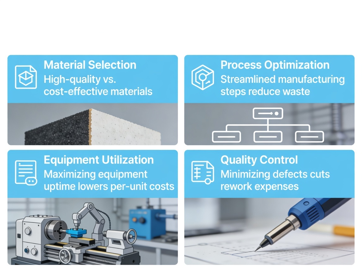
Cost optimization in flex PCB fabrication requires understanding the structural factors that drive pricing. The primary cost drivers include board materials, layer count, efficient panel utilization, type of stiffeners, and surface finish. U.S. engineers and procurement teams who understand these levers can make design choices that reduce cost without compromising performance.
Layer Count — The Dominant Cost Variable
Layer count is a critical cost driver in flexible PCB design and layout. As layer count increases, the lamination process becomes more complex and costly, while yield rates typically decline due to the compounding effect of registration tolerances across multiple layers. A 2-layer flex PCB is typically approximately 50% more expensive than a 1-layer configuration. Similarly, moving from 2 layers to 4 layers can add another 40-60% cost premium. These are rough benchmarks — actual cost impact depends on design complexity, material selection, and fabrication volume.
Material Selection and Its Cost Implications
Material costs are directly proportional to copper foil thickness — thicker copper increases prepreg consumption during lamination and raises material expense per panel. Beyond copper thickness, the choice between adhesiveless and adhesive-based polyimide laminates significantly affects cost: adhesiveless copper is more expensive but often proves cost-effective in high-layer-count designs where the reduced thickness and improved thermal performance justify the premium.
Panel Utilization Efficiency
Flex circuit designs that efficiently utilize the fabrication panel — minimizing wasted space — reduce cost per unit. Irregular board shapes, large keep-out zones, and non-standard dimensions can dramatically reduce panel utilization, effectively increasing the cost allocated to each deliverable circuit. Early DFM engagement with the fabrication partner can identify panelization strategies that maximize utilization.
Stiffener Type and Surface Finish
The type and quantity of stiffeners significantly impact fabrication cost. FR-4 stiffeners are the most economical option, while aluminum, copper, and polyimide stiffeners carry progressively higher material and processing costs. Surface finish selection — ENIG, Immersion Silver, Immersion Tin, or HASL — also affects cost, with ENIG typically commanding a premium due to its superior flatness and shelf-life characteristics.
Cost-Saving Strategies That Preserve Quality
For U.S. buyers seeking cost-competitive flex PCB fabrication without compromising reliability:
- Engage the fabricator during the design phase — DFM feedback can eliminate cost-prohibitive design features before they are baked into the specification.
- Standardize material callouts where possible — specifying commonly stocked polyimide thicknesses and copper weights avoids custom material procurement charges.
- Consolidate stiffener types — minimizing the number of unique stiffener specifications per design reduces tooling and handling costs.
- Optimize for panel utilization — work with the fabricator to adjust outline dimensions or panelization strategies.
- Plan volume strategically — prototype quantities carry a significant premium compared to production volumes; consolidating prototype builds across multiple designs can sometimes yield volume discounts.
Flex PCB vs. Rigid-Flex PCB — Which Fabrication Route Fits Your Application?
One of the most frequent decision points facing U.S. design engineers is whether to pursue a pure flex PCB fabrication path or to adopt a rigid-flex architecture. While both technologies share polyimide as a core material, their applications, cost profiles, and design considerations diverge significantly.
Flex PCB — When Pure Flexibility Is the Answer
A flex PCB uses only flexible polyimide substrate throughout the entire circuit, with no rigid sections. This construction excels in applications where the circuit must:
- Undergo repeated dynamic bending during product operation, such as in printer head cables, robotic joint interconnects, and hinge mechanisms in foldable electronics.
- Conform to curved or irregular surfaces within a product enclosure.
- Replace wire harnesses and connectors to reduce assembly labor, part count, and potential failure points.
- Achieve extreme weight reduction — flex circuits can be up to 70% lighter than equivalent rigid boards.
Flex PCBs are very light compared to rigid PCBs, offer space-saving advantages for compact designs, and can bend and conform to different shapes throughout the product lifecycle.
Rigid-Flex PCB — The Best of Both Worlds
Rigid-flex PCBs combine rigid FR-4 sections with flexible polyimide interconnects in a single fabricated unit. The rigid sections provide mechanical stability for component mounting and connector interfaces, while the flexible sections enable three-dimensional routing through confined geometries. This architecture allows the circuit to fold or route through limited geometry, translating to better packaging efficiency and fewer connectors in end products.
Rigid-flex construction eliminates the connectors and cables that would otherwise bridge rigid boards in a multi-board system. Eliminating these interconnects reduces assembly time, component count, and the reliability risks associated with connector mating cycles and cable fatigue. This makes rigid-flex particularly attractive for aerospace, defense, medical devices, and high-end consumer electronics where reliability and miniaturization are paramount.
Comparison Table — Flex PCB vs. Rigid-Flex PCB
| Criteria | Flex PCB | Rigid-Flex PCB |
|---|---|---|
| Substrate | Polyimide throughout | FR-4 rigid sections + polyimide flex sections |
| Component mounting | Limited; mainly on stiffened areas | Full SMT on rigid sections |
| Connector elimination | Partial — reduces cable count | Complete — eliminates board-to-board connectors |
| Design complexity | Moderate | High — requires careful rigid-flex transition zone design |
| Relative cost | Lower than rigid-flex equivalent | Higher due to complex lamination and transition zone processing |
| Ideal applications | Dynamic bending, cable replacement, curved mounting surfaces | 3D packaging, multi-board integration, high-reliability aerospace/medical |
| Typical layer range | 1–10 layers (flex only) | 2–16+ layers (combined) |
Decision Framework for U.S. Engineers
When evaluating fabrication routes, U.S. engineers should consider:
- Mechanical Requirements: Does your design require dynamic flexing throughout the product lifecycle, or is the flex needed only for installation and assembly?
- Component Density: Do you need to mount components on flexible sections? (If yes, rigid-flex or stiffened flex is indicated.)
- System-Level Packaging: Can the system architecture be consolidated from multiple boards into a single rigid-flex assembly?
- Reliability Budget: What are the consequences of a connector failure in your application?
- Cost Sensitivity: How does the per-unit cost of rigid-flex compare to the combined cost of multiple rigid boards plus connectors, cables, and assembly labor?
Explore BESTFPC's rigid-flex PCB manufacturing capabilities for more detailed technical guidance on fabrication-friendly rigid-flex design.
Lead Time, Supply Chain, and Tariff Realities for Flex PCB Fabrication Sourcing into the U.S. Market
U.S. procurement teams navigating flex PCB fabrication sourcing in 2026 face a complex landscape shaped by tariff structures, supply chain lead times, and logistics considerations. Understanding these dimensions is essential for accurate project planning and total-cost-of-ownership analysis.
Industry-Standard Flex PCB Fabrication Lead Times
Lead times for flex PCB fabrication vary significantly based on complexity, layer count, and production volume. For rapid-turn prototypes, U.S. domestic suppliers typically offer lead times of 5 working days for standard flex designs, while offshore manufacturers range from 7 to 20 days depending on complexity and expediting options. Production volumes extend these timelines further: U.S. domestic volume production typically falls in the 2-4 week range, while offshore production cycles range from 3 to 5 weeks.
High-layer-count or specialty designs that require sequential lamination, controlled impedance, or advanced materials should budget an additional 3-7 days for fabrication complexity. BESTFPC operates a 3,000㎡ facility with 200+ staff and a daily peak capacity of up to 100,000 pieces, enabling competitive lead times for both prototype and volume production.
U.S. Tariff Impact on Flex PCB Fabrication Costs (2026 Update)
The tariff landscape for Chinese-manufactured PCBs imported into the United States has been dynamic and is projected to remain fluid throughout 2026. As of early 2026, flex and rigid-flex PCBs face Section 301 tariffs of 25% on top of standard Most-Favored-Nation rates, plus additional IEEPA tariffs of 10% — resulting in a total effective tariff rate of approximately 35% for flex PCBs from China. Some semiconductor-related PCB categories have faced tariffs as high as 50% on top of standard rates.
U.S. importers have benefited from Section 301 tariff exclusions that have been extended through November 2026 for qualifying Chinese-manufactured PCBs. U.S. buyers should verify whether their flex PCB import classifications qualify for current exclusion programs and factor tariff exposure into their total-cost calculations.
Strategies for Mitigating Tariff and Lead Time Risk
- Verify Tariff Classification: Work with a customs broker to confirm the correct HTS code for your specific flex circuit type.
- Factor Tariff Costs into TCO Models: Include all landed costs when comparing U.S. domestic and international suppliers.
- Diversify Sourcing Geographies: Evaluate qualified suppliers in multiple manufacturing locations to create tariff and logistics flexibility.
- Build Inventory Buffers: Hold strategic safety stock for high-volume, recurring flex circuit designs to insulate against lead time variability.
- Leverage DFM for Cost Reduction: Early supplier engagement to optimize designs for panel utilization and material yield can offset a portion of tariff-related cost increases.
Why More U.S. Engineering Teams Are Choosing BESTFPC for Flex PCB Fabrication
Throughout this guide, we have examined the factors that U.S. engineers and procurement professionals weigh when selecting a flex PCB fabrication partner: manufacturing capability, quality certifications, material expertise, cost transparency, supply chain stability, and application-specific experience. BESTFPC's value proposition aligns with each of these evaluation dimensions in ways that directly address the decision-making criteria of sophisticated U.S. buyers.
20 Years of Focused Flex PCB Fabrication Expertise
BESTFPC (Best Technology Co., Ltd.) is not a general-purpose PCB fabricator that happens to offer flex circuits as a secondary product line. The company is a dedicated flex and rigid-flex PCB manufacturer with 20 years of specialized experience, focusing exclusively on small-batch, multi-class, high-quality, on-time flexible products. This focused specialization means the engineering team, production processes, quality systems, and supply chain are all built around the unique requirements of flexible circuit manufacturing — not adapted from a rigid PCB production mindset.
Comprehensive Manufacturing Capability Under One Roof
BESTFPC operates a 3,000㎡ manufacturing facility with 200+ staff and complete one-stop production capability — from rigid-flex PCB and multilayer flex PCB fabrication to special FPC boards — without outsourcing any critical process steps. This vertical integration delivers three concrete benefits for U.S. buyers:
- Tighter Quality Control: In-house control over every process step enables consistent quality outcomes and faster root-cause analysis when issues arise.
- Faster Lead Times: Eliminating the handoffs and transportation delays inherent in outsourced process steps compresses the overall fabrication timeline.
- Clear Accountability: When a single company owns the entire fabrication chain, responsibility for quality, delivery, and corrective action is unambiguous.
Global Certifications That U.S. Buyers Demand
BESTFPC's certification portfolio — ISO, IATF, SGS, and UL — covers the essential quality, safety, and industry-specific standards that U.S. procurement teams require. For medical device customers, which represent a substantial portion of BESTFPC's business, the fabrication processes are aligned with the rigorous requirements of IPC-6013 and the IPC-6013EM medical addendum.
Deep Industry Expertise in Medical, Automotive, and Consumer Electronics
BESTFPC serves customer industries including automotive, medical, industrial, consumer electronics, and emerging markets, with medical and smart wearable devices accounting for approximately 80% of the company's export volume. This concentration in regulated, high-reliability markets has shaped BESTFPC's quality culture and process discipline in ways that benefit all customers, regardless of industry. When a fabrication partner routinely manufactures circuits for medical implantables and wearable health monitors — applications where field failure is simply not an option — the process rigor developed for those markets elevates quality across the entire product portfolio.
Responsive Engineering Support and Competitive Quotation Speed
BESTFPC has built a reputation for strong customer support and technical expertise — qualities that make the company a go-to resource for engineers seeking a reliable flexible PCB manufacturing partner. Upon receiving an RFQ, the team prioritizes a swift response, delivering competitive quotations within a rapid timeframe to support U.S. buyers' project timelines.
Proven Track Record with U.S. Customers
BESTFPC has established itself as a trusted flexible printed circuit source capable of accommodating customized program initiatives, with product lines encompassing single-sided flex circuits, dual-access flexible PCBs, double-sided flexible circuits, multi-layer flex circuits, and rigid-flex circuits. Customers recognize BESTFPC's commitment to quality, with flex circuits that follow government and industry regulatory requirements.
.png)
.png)
.png)
.png)

.png)

