


 2026-10-26

 BEST
BestFPC is a China-based manufacturer providing custom multilayer flex PCB manufacturing services for customers in the USA. For engineers, buyers and project managers, selecting a supplier starts with matching the stackup, fabrication limits and inspection requirements to a design that can be quoted and manufactured consistently.
BestFPC supports custom flex stackups, manufacturing review and PCB assembly services, helping your team connect bare-board requirements with downstream assembly needs. Share your layer structure, bend requirements and expected quantities so we can review the proposed manufacturing route and identify items requiring clarification. Send your project details to sales@bestpcbs.com to begin the quotation and engineering discussion.
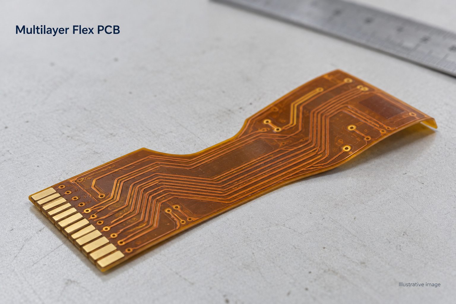
Multilayer Flex PCB Manufacturing Capabilities at BestFPC
BestFPC supports four- and six-layer flex PCBs within its standard capability range, with eight-layer designs subject to special-process review. Compare your design with the parameters below. Final capability depends on the combination of layer count, copper thickness, hole structure and materials.
| Manufacturing item | Capability | Conditions for review |
|---|---|---|
| Flex layer count | Standard range: 1–6 layers; special range: 2–8 layers | Multilayer stackup and process route require confirmation |
| Inner-layer line width / spacing | 3 / 3 mil at 18 µm copper; 4 / 4 mil at 35 µm copper | Standard values before artwork compensation |
| Outer flex-layer line width / spacing | 5 / 4.5 mil at 18 µm copper; 5.5 / 5 mil at 35 µm copper | Standard values before artwork compensation |
| Minimum mechanical drill diameter | 0.15 mm | Listed for board thickness up to 1.6 mm; drill diameter is not finished-hole diameter |
| Adhesiveless PI base material | 0.5, 1, 2 and 3 mil PI; ⅓, ½, 1 and 2 oz copper options | Available combinations and final stackup require review |
| Maximum standard finished inner copper | 2 oz | Distinguish finished copper from starting foil thickness |
| Controlled impedance | ±10% tolerance | Requires an agreed stackup and impedance specification |
| Surface finishes | ENIG, electroplated gold, OSP and tin plating | Select for the contact and assembly requirements |
For laser-drilled plated holes, diameter, depth and connection pattern are reviewed separately from mechanical drilling limits. Send both the desired finished-hole size and the layer-to-layer connection requirements with your inquiry.
Multilayer Flexible PCB Stackup Options
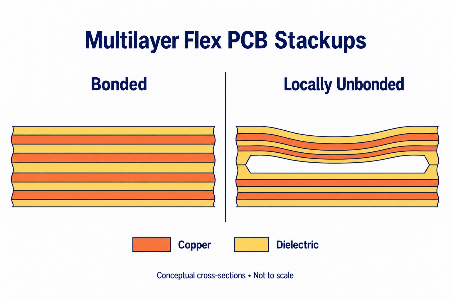
A multilayer flexible PCB can use bonded construction or leave selected layer groups unbonded. Local separation is one implementation of an unbonded structure, with separation confined to defined regions.
- Bonded stackup: Layers remain bonded across the designated flex structure. Review the complete copper, dielectric, adhesive and coverlay build when assessing thickness and bend suitability.
- Unbonded layer groups: Selected flex subassemblies remain separated over a specified length. The drawing must identify the separated groups, bonding boundaries and locations where electrical interconnections are permitted.
- Locally separated regions: Keep the required areas bonded while defining separation where the mechanical layout calls for it. Manufacturing documentation must show where separation begins and ends and how the layers transition into the bonded sections.
For BestFPC’s stackup review, provide the installed shape, available space, intended bend locations and whether bending occurs during installation or repeatedly in service. Repeated bending requires design-specific evaluation of the full construction. Define any unbonded regions explicitly in the stackup drawing.
Multilayer Flex PCB vs. Multilayer Rigid Flex PCB
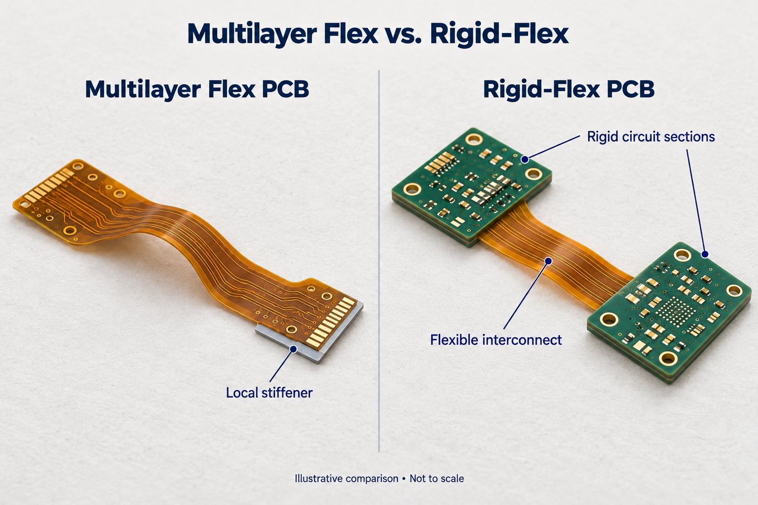
Choose between multilayer flex and multilayer rigid-flex PCB construction according to component support, interconnection and mechanical requirements. Adding an FR4 stiffener to a flex board does not create a rigid-flex circuit: a stiffener provides mechanical support, while rigid-flex includes rigid circuit regions.
| Selection factor | Multilayer flex PCB | Multilayer rigid-flex PCB |
|---|---|---|
| Structure | Flexible circuit layers, with optional local stiffeners | Integrated rigid circuit sections and flexible interconnections |
| Bend requirements | Define bends within the flex construction | Define bends in flex sections and protect rigid-to-flex transitions |
| Space constraints | Assess the flex envelope and any stiffener thickness | Assess rigid-board envelopes and connecting flex lengths |
| Component support | May require local stiffeners and assembly fixtures | Rigid sections provide component mounting areas |
| Manufacturing complexity | Driven by layer count, separation, holes and local thickness changes | Also involves integrating rigid and flexible regions |
| Cost assessment | Evaluate fabrication, stiffeners, fixtures and assembly | Evaluate board construction alongside connector and system assembly needs |
Neither structure is automatically the lower-cost choice. Compare the complete assembled solution, including connectors, mechanical support and inspection, before selecting the PCB architecture.
DFM Review for Multilayer Flex Circuits
BestFPC’s manufacturing review helps identify conflicts between the circuit files, stackup and mechanical requirements before fabrication. This helps your team resolve manufacturing questions while changes can still be made in the design files.
- Gerber and fabrication notes: Check layer identification, outline, coverlay openings and drill information against the drawing. Resolve conflicting dimensions or tolerances before releasing production files.
- Stackup and impedance: Match dielectric thickness, copper and reference layers to the requested impedance. Confirm any proposed material or geometry change with the customer.
- Bend areas and via placement: Identify holes, pads or routing features that may conflict with the intended bend. Review their positions using the actual bend geometry and operating conditions.
- Stiffeners and local transitions: Check stiffener boundaries, adhesive thickness, connector insertion areas and access for assembly. Clarify transitions between thick and thin regions.
For efficient engineering communication, keep each question tied to a drawing location and file revision. A revised stackup or marked-up drawing gives your team a clear approval point before fabrication begins.
Multilayer Flex PCB Manufacturing Case Study for a USA Customer
BestFPC’s US customer project features a four-layer FPC with a 1+2+1 construction and a thinner two-layer region. The design combines multilayer routing with a localized reduction in thickness within a 27.60 × 12.59 mm outline.
Customer Application
As an application example, this construction can serve as an internal sensor-to-controller interconnect in a compact wearable device. The four-layer section provides routing space for electrical connections, while the thinner two-layer section offers a lower-profile path through the enclosure, with bend geometry matched to the installation.
Customer Requirements
| Parameter | Specification |
|---|---|
| Layer structure | Four layers, 1+2+1 |
| Individual board size | 27.60 × 12.59 mm |
| Overall flex thickness | 0.33 ±0.05 mm |
| Two-layer region thickness | 0.11 ±0.03 mm |
| Inner dielectric | 1 mil adhesiveless PI |
| Copper | Inner: ½ oz; outer: 1 oz |
| Surface finish | ENIG, specified gold thickness 1 µin |
| Protective layers | Yellow coverlay and local yellow solder mask |
| Holes | Laser-drilled; all holes copper plated |
Manufacturing Challenges
The key manufacturing challenge is controlling the thickness of both regions while managing their transition. The compact outline also requires accurate alignment of circuit features and laser-drilled holes. Layer registration, plating and coverlay placement need to follow the approved stackup without changing the intended thin-section geometry.
BestFPC’s Manufacturing Solution
- Region-specific stackup: The 1+2+1 structure provides four-layer routing where needed while retaining the designated two-layer section. Clearly defined transition boundaries align the fabrication build with the mechanical layout.
- Material and copper selection: The 1 mil adhesiveless PI inner material supports a thin dielectric build without a separate copper-to-PI adhesive layer. The ½ oz inner and 1 oz outer copper are incorporated into the regional thickness calculations rather than treated as interchangeable options.
- Plated laser-drilled holes: Hole locations and layer connections are reviewed together with registration and plating requirements to support electrical interconnection within the compact board.
- Production-file approval: BestFPC submits the manufacturing files for customer approval against the confirmed stackup, aligning thicknesses, layer transitions and hole details before production.
Customer Benefits
The 1+2+1 construction combines four-layer circuit routing with a thinner two-layer section within a compact 27.60 × 12.59 mm board. This configuration gives engineers greater flexibility when arranging electrical connections and accommodating limited installation space. The defined stackup also provides a clear basis for manufacturing review and downstream assembly planning.
Assembly and Quality Control for Multilayer Flexible PCBs
BestFPC provides flex PCB assembly services covering component sourcing, SMT and prototype-to-volume builds. Bare-board inspection and assembly testing are coordinated around the approved design and order requirements.
Assembly Services
- Component Sourcing: Choose full turnkey, partial turnkey or consigned components. BOM review helps address part-number, package and availability questions before purchasing.
- SMT Assembly: Printing, placement and reflow are planned around the flex construction and component layout. Assembly capability includes 0201 packages for compact designs, subject to layout review.
- Stiffener Integration: Coordinate reinforcement, connector fit and assembly access so supported areas match the mechanical requirements.
- Assembly Fixtures and Handling: Plan carriers and fixtures to support thin flex regions during printing and placement, limiting movement during assembly.
- Prototype and Volume Assembly: Establish the approved files and first-article requirements during prototyping, then carry the agreed build controls into repeat orders.
Quality Control and Testing
BestFPC’s quality control process includes incoming, in-process and final checks. The inspection plan distinguishes bare-board fabrication from PCBA verification; X-ray, ICT and functional testing are selected according to the design and agreed scope.
| Inspection or test | Stage | Purpose |
|---|---|---|
| Incoming material inspection | Bare board and assembly | Check specified materials, component identity and incoming condition |
| Dimensional and visual inspection | Bare board and assembly | Check outline, regional thickness, coverlay, stiffener position and visible workmanship as applicable |
| AOI | Circuit fabrication and assembly | Detect circuit-pattern defects or visible component and soldering issues at the relevant stage |
| SPI | Assembly, after paste printing | Check solder-paste deposits before component placement |
| X-ray inspection | Selected assemblies | Examine hidden solder joints for issues such as bridging or voiding |
| Electrical testing | Bare board | Check continuity and isolation against the circuit netlist |
| ICT and functional testing | Assembly, where specified | Check accessible circuit nodes and agreed operating functions using suitable fixtures and test criteria |
One coordinated fabrication, assembly and inspection plan helps US customers reduce supplier handoffs and keep acceptance requirements consistent. Agreed revision, material-lot and inspection records also support repeat-order quality management.
Multilayer Flex PCB Cost, Lead Time and Shipping to the USA
Multilayer flex PCB pricing and delivery schedules depend on the approved design, quantity and service scope. Obtain a project-specific quotation that separates fabrication, assembly, testing and shipping where applicable.
- Cost drivers: Layer count, separated regions, local thickness changes, copper requirements, hole structures and panel utilization affect the manufacturing route. Stiffeners, components, fixtures and additional testing also belong in the cost comparison.
- Order quantities: Provide prototype quantities and expected production volumes. Ask BestFPC to confirm the minimum order quantity, quantity-based pricing and any material purchasing requirements for the proposed construction.
- Production timing: Confirm material availability, engineering approval, fabrication, assembly and inspection milestones. Prototype and repeat-production schedules should be quoted separately, with the lead-time starting point stated clearly.
- US delivery: Confirm the destination, shipping method, freight charges, trade terms and responsibility for customs clearance and import charges in the quotation or order agreement.
Factory completion and arrival at your US receiving location are separate milestones. Include transit and clearance in the project schedule, and confirm whether a quoted delivery date refers to shipment or receipt.
Why Choose BestFPC as Your Multilayer Flex PCB Manufacturer for the USA?
BestFPC brings custom flex fabrication, engineering review and assembly options into one supplier discussion. For US buyers, the practical value is a clearly agreed manufacturing plan that connects design requirements with inspection and delivery expectations.
- Stackup support: Review the construction against your available space, connections and bend requirements before committing to fabrication.
- Engineering coordination: Resolve manufacturing questions through an agreed contact and approval process, helping your team keep design changes under control.
- PCB and PCBA services: Coordinate bare-board and assembly requirements together, reducing the number of separate technical handoffs your purchasing team must manage.
- Defined quality requirements: Match inspection and documentation to the order so your receiving team knows what evidence to expect.
- US customer project experience: Experience with a US four-layer FPC project involving different regional thicknesses and plated laser-drilled holes supports practical discussions about compact interconnect manufacturing.
- Prototype-to-production support: Establish the approved revision and acceptance criteria during prototyping, then confirm materials, quantities and test requirements for the production release.
FAQs About Multilayer Flex PCB Orders from the USA
What files should I submit for a multilayer flex PCB quotation?
Send Gerber files, drill files, a fabrication drawing, stackup and required quantities. Include bend and impedance requirements where relevant. For assembly, add the BOM, component placement file and assembly drawing, plus any test specification.
Can BestFPC review the project if my fabrication files are not finalized?
Yes. Share the available drawings and requirements for a preliminary review. The review identifies the details needed to develop a complete manufacturing package and a firm quotation.
Can we arrange an NDA before sharing our design files?
Raise the NDA request before sending confidential files. Confirm the contracting entity, terms and execution of the agreement with BestFPC before releasing protected information.
How are engineering questions and file revisions approved before production?
Agree on the approval contact and communication method at the start. Reference each response to the relevant revision, and confirm the final production package in writing so superseded files are not mistaken for approved instructions.
What should we confirm before placing a repeat order?
Confirm the part number and revision, any design or material changes, quantities and acceptance requirements. Identify differences from the previous order explicitly rather than relying only on the old purchase order number.
Can we request inspection reports or a certificate of conformity with the shipment?
List the required documents when requesting a quote. BestFPC will review the requested scope, availability, format and any additional cost as part of the order discussion.
Can we use our own freight forwarder or courier account for US delivery?
Request this arrangement during quotation and provide the proposed carrier or forwarder details. Confirm feasibility, collection instructions and required shipping documents with BestFPC before dispatch.
Send your design files, expected quantities and US delivery requirements to sales@bestpcbs.com. BestFPC can review the project and confirm the manufacturing, inspection and quotation details needed for your next purchasing decision.


.png)
.png)
.png)
.png)

.png)