


 2025-08-27
 BEST
BEST
You face increasing pressure to select the best automobile display flexible circuit board for vehicles that demand reliability and advanced performance. Flexible PCBs have transformed automotive electronics, offering unique advantages in compact, vibration-prone environments. Flexible printed circuit boards excel in infotainment and safety systems, replacing bulky wire harnesses and improving durability. The global market for flexible PCBs in automotive applications is projected to reach $47.9 billion by 2032, underscoring their expanding role in vehicles. Material choice, such as polyimide, directly impacts thermal stability and flexibility, which are essential for electronics exposed to harsh automotive conditions.
Durability and adaptability set flexible PCBs apart in vehicles, making them critical for automotive display flexible circuit boards.
Key Takeaways
- Choose polyimide flexible PCBs for automotive displays to ensure high thermal stability, flexibility, and durability in harsh vehicle environments.
- Design flexible PCBs with proper bend radius and material stack-up to maintain reliability and prevent damage during repeated flexing.
- Select suppliers with automotive certifications like IATF 16949 and IPC-6013 to guarantee quality and compliance with strict industry standards.
- Use pilot runs and process validation to identify and fix production issues before mass manufacturing, ensuring consistent high-quality boards.
- Implement thorough quality control with advanced inspections and environmental testing to confirm your flexible PCBs withstand vibration, temperature, and moisture.
Display Flexible PCBs Selection Criteria
Choosing the right flexible PCB for automotive electronics requires you to evaluate several critical factors. You must ensure that the flexible PCBs you select meet the demanding standards of vehicles, where reliability and durability are non-negotiable. Understanding how to choose the right flexible PCB for your automotive display systems will help you avoid costly failures and maximize performance.
Electrical Performance
Electrical performance stands at the core of flexible PCBs for automotive electronics. You need to ensure that your flexible PCBs comply with IPC-6012 Class 3 and automotive standards like IATF 16949 and AEC-Q100. These standards guarantee long-term reliability, signal integrity, and safety for electronics in vehicles. Polyimide substrates offer low dielectric constants and minimal water absorption, supporting high signal integrity even in harsh automotive environments.
Tip: Always check for EMI shielding layers and proper grounding to prevent electrical noise and interference in automotive electronics.
| Material | Dielectric Constant | Signal Integrity | EMI Shielding | Flexibility |
|---|---|---|---|---|
| Polyimide | Low | High | Optional | Excellent |
| Polyester (PET) | Moderate | Moderate | Optional | Poor |
| FR4 | Moderate | Good | Optional | Limited |
Dielectric thickness directly affects both flexibility and electrical performance. Thinner layers allow tighter bend radii, but may increase capacitance and crosstalk. Thicker dielectrics improve isolation but reduce flexibility. You should balance these factors to maintain optimal performance in automotive electronics.
Mechanical Flexibility
Mechanical flexibility is essential for flexible PCBs used in vehicles, especially in display systems, sensors, and lighting. You must test mechanical flexibility through bend tests, including static and dynamic cycles, to simulate real-world stresses.
- Static bend tests measure tensile and compressive stress, checking for cracks or delamination.
- Dynamic bend tests assess endurance by cycling the PCB over a defined radius.
- Push-to-flex and roll-to-flex tests evaluate multi-directional bending and tight tolerances.
IPC-6013 and IPC-TM-650 standards guide these tests, requiring no visible damage after bending. For automotive displays, engineers recommend a minimum bend radius of 10 times the board thickness. For example, a 0.2 mm thick thermoformed flex PCB should have a minimum bend radius of 2 mm. This guideline ensures that your flexible PCBs maintain reliability and signal integrity under repeated flexing in vehicles.
Note: Rolled-annealed copper foil enhances flexibility and resists cracking, making it ideal for thermoformed flex PCBs in automotive electronics.
Thermal Stability
Thermal stability is a must for flexible PCBs in automotive electronics. You need materials that withstand extreme temperatures, typically from -40°C to +150°C, as required by standards like AEC-Q100 and ISO 26262. Polyimide substrates excel in thermal stability, maintaining performance from -55°C to over 200°C. High-Tg laminates (Tg ≥ 170°C) are recommended for rigid sections to resist deformation during thermal cycling.
Thermal cycling causes expansion and contraction, leading to mechanical stress and potential failure. You should select adhesives and coverlay materials that resist thermal degradation and moisture absorption. Conformal coatings and sealed board edges help reduce moisture ingress, extending the lifespan of your flexible PCBs.
| Feature | Polyimide (PI) | Polyester (PET) | FR4 |
|---|---|---|---|
| Thermal Resistance | Stable up to 200°C | Limited to below 80°C | Degrades above 130°C |
| Mechanical Durability | High, repeated bending | Prone to cracking | Moderate |
| Chemical Resistance | Resistant to solvents and oils | Less resistant | Good |
| Flexibility | Highly flexible | Poor | Less flexible |
Reliability
Reliability defines the success of flexible PCBs in automotive electronics. You must ensure that your thermoformed flex PCBs endure long-term use, vibration, and harsh conditions in vehicles. Polyimide-based flexible PCBs outperform polyester and FR4 in failure rates due to superior thermal resistance, mechanical strength, and chemical durability.
- Thermal cycling tests simulate expansion and contraction, revealing failure modes like microcracking and delamination.
- Moisture absorption can cause short circuits and leakage currents, so you should use high-temperature adhesives and conformal coatings.
- Matching coefficients of thermal expansion between rigid and flexible sections reduces stress and improves reliability.
Flexible PCBs for sensors and lighting in vehicles require robust design and material selection to maintain electrical functionality after mechanical and thermal testing. Adhesiveless substrates further improve flexibility and reliability by reducing thickness and enhancing resistance to delamination.
Callout: Prioritize polyimide substrates and rolled-annealed copper for your automotive electronics to achieve the highest reliability and performance in flexible PCBs.
Material Selection for Flex PCBs
Selecting the right materials for flexible PCBs in automotive electronics is crucial for long-term performance and reliability. You must weigh the benefits of polyimide base materials and flex-rigid PCB options to meet the demanding requirements of automotive environments.
Polyimide Base Material
Polyimide stands out as the preferred substrate for thermoformed flex PCBs in automotive electronics. You gain several key advantages by choosing polyimide:
- Superior heat resistance: Polyimide maintains structural integrity and electrical performance above 250°C, outperforming traditional materials like FR4.
- Excellent flexibility: You can bend, twist, and fold polyimide-based flexible PCBs without damage, making them ideal for tight or curved automotive spaces.
- Strong chemical and moisture resistance: Polyimide withstands solvents, oils, and moisture, which are common in automotive environments.
- High dielectric strength: This ensures stable electrical insulation under high voltage and frequency conditions.
- Lightweight and thin: Polyimide supports miniaturization and compact design, which are essential for modern automotive electronics.
- Mechanical endurance: These flexible PCBs handle vibrations and shocks, which are typical in automotive applications.
Tip: Polyimide flexible PCBs deliver enhanced durability and reliability, making them the top choice for automotive display systems.
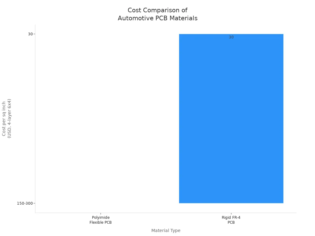
However, you must consider cost. Polyimide is a premium material, often costing 5-10 times more than rigid FR-4 and significantly more than polyester (PET). The manufacturing process for thermoformed flex PCBs with polyimide is complex, leading to higher costs and lower yields. Despite this, the advantages of thermoformed flex PCBs justify the investment for critical automotive electronics.
Flex-Rigid PCB Options
Flex-rigid PCBs combine rigid and flexible sections, giving you the best of both worlds for automotive electronics. You benefit from:
- The ability to bend, fold, or twist the flexible sections without losing electrical performance.
- High resistance to shock and vibration, which is vital for automotive environments.
- Increased packaging density and reduced system weight, supporting compact automotive designs.
- Simplified assembly by reducing connectors and solder joints, which improves reliability.
- Compliance with strict quality and thermal resistance standards, ensuring long lifespan.
However, flex-rigid PCBs come with higher manufacturing costs and longer production cycles. The flexible areas may face material limitations under extreme mechanical stress or temperature. You should use flex-rigid PCBs in automotive applications where reliability, compactness, and environmental resistance are critical, such as dashboard displays and control modules.
| Feature | Single-layer Flexible PCBs | Flex-Rigid (Rigid-Flex) PCBs |
|---|---|---|
| Flexibility | Very high; suitable for dynamic bending and folding | Partial flexibility; bend radius 6-10x flex thickness |
| Durability | Good for dynamic applications | Enhanced durability; withstands high vibration |
| Construction | Single flexible substrate (polyimide) | Hybrid of rigid FR-4 and flexible polyimide layers |
| Applications | Wearables, foldable devices | Automotive, aerospace, medical, complex geometries |
| Cost | High | Higher due to complex fabrication |
When you select materials for flexible PCBs in automotive electronics, always balance flexibility, durability, and cost. Typical applications of thermoformed flex PCBs include infotainment displays, instrument clusters, and advanced driver-assistance systems. These solutions provide the flexibility and reliability needed for modern automotive electronics.
Car FPC Boards Supplier Evaluation
Qualification
When you evaluate suppliers for automotive display flexible circuit boards, you must focus on strict qualification standards. Automotive electronics demand higher reliability than consumer devices. Suppliers must meet certifications such as IATF 16949, ISO 9001, IPC-6013D, and RoHS. These standards ensure that your supplier follows robust quality management systems and delivers consistent products.
| Manufacturer | Relevant Certifications for Automotive Flexible Circuit Boards |
|---|---|
| ASC | IATF 16949, ISO 9001, MIL-PRF-31032, AS9100, ISO 13485 |
| TTM Technologies | ISO 9001, IPC-6013D, AS9100, IATF 16949 |
| Best FPC | ISO 9001, ISO 13485, UL, RoHS, IATF 16949 |
Automotive qualification processes go beyond basic testing. You must verify that suppliers can handle extreme temperatures, humidity, vibration, and electromagnetic interference. Automotive standards like AEC-Q100 require higher ESD withstand voltages and detailed reporting. Suppliers must also provide documentation for traceability and pass rigorous audits before onboarding.
Tip: Always request evidence of certifications and recent audit reports from your supplier. This step helps you avoid costly failures and ensures compliance with automotive requirements.
Quality Assurance
You need suppliers who implement advanced quality assurance protocols. Automotive manufacturers audit suppliers for compliance with IATF 16949 and process control measures. They check for tight tolerance management, high-precision tools, and continuous real-time monitoring during fabrication. Automated Optical Inspection (AOI), including 3D AOI, detects soldering defects and misalignments. Electrical testing methods such as in-circuit testing and boundary scan verify component integrity.
- Suppliers must maintain documentation for traceability, including design files and production logs.
- Continuous improvement programs use Failure Mode and Effects Analysis (FMEA) to reduce defect rates.
- Factory audits assess cleanliness, organization, and risk reduction strategies.
- Statistical Process Control (SPC) monitors production processes for consistent results.
Automotive manufacturers also require suppliers to perform incoming quality control of raw materials and final outgoing inspections. These steps confirm that every flexible PCB meets your specifications and industry standards.
Note: Reliable suppliers invest in regular calibration of testing equipment and maintain compliance with IPC-A-610, ISO 9001, and RoHS. This commitment to quality ensures your automotive display flexible circuit boards perform safely and consistently.
Design for Automotive Display Flexible Circuit Board

Manufacturability
When you design an automobile display flexible circuit board, you must prioritize manufacturability. Flexible PCBs for automotive applications require careful selection of materials and stack-ups. Polyimide substrates offer mechanical strength and thermal resistance, making them ideal for harsh automotive environments. You should collaborate with fabricators early, sharing stackup details and confirming material availability. Place stiffeners at least 50 mils away from vias to prevent cracking, and use thermally cured acrylic adhesives for permanent bonds. Always respect the recommended bend radius—at least 6-10 times the total thickness—to avoid copper trace damage. Provide clear Gerber files and detailed drawings that specify bend radius, impedance, and surface finish. These steps ensure your flexible PCB for sensors and lighting meets quality standards and survives repeated flex cycles.
| Design Aspect | Guideline/Recommendation |
|---|---|
| Stiffener Materials | Polyimide (0.1-0.5 mm), FR4 (0.8-1.6 mm), aluminum/stainless steel for high-stress areas |
| Stiffener Placement | ≥50 mils from vias |
| Adhesive Thickness | ≤10% of total construction |
| Documentation | Gerber files, bend radius, impedance, surface finish |
| Testing | Flex cycle, environmental, IPC-6013, IPC-2223 compliance |
Scalability
Scaling flexible PCBs from prototype to mass production introduces unique challenges. You must optimize designs for manufacturability, using standard component sizes and maintaining proper spacing. Reliable supply chains and buffer stocks help you avoid delays, especially for high-volume automotive production. Automated optical inspection and in-circuit testing maintain quality across thousands of units. Design choices, such as strategic via placement and bend radius compliance, directly impact scalability by reducing defects and improving yield. Advanced manufacturing technologies, including laser processing and automated assembly, enhance precision and repeatability. These strategies ensure your automobile display flexible circuit board performs reliably in tight dashboard spaces and meets the demands of automotive sensors.
Cost Optimization
Cost optimization is essential when designing thermoformed flex PCBs for automotive displays. You can reduce costs by minimizing the number of layers and components, selecting cost-effective substrates, and optimizing trace spacing. Use standard panel sizes to decrease material waste and choose reputable manufacturers with strong supply chain management. Bulk purchasing and automated assembly lower per-unit costs. Arrange components logically to minimize assembly errors and time. Continuous improvement and standardization further reduce variability and expenses. By focusing on these strategies, you maintain high performance without compromising quality in your flexible PCB for lighting and sensors.
Tip: Collaborate with manufacturers on sustainability initiatives to reduce waste and disposal costs, supporting both your budget and environmental goals.
Testing Protocols
Testing for reliability is critical in automotive flexible PCB design. You must conduct flex cycle testing, environmental stress analysis, and adhere to IPC standards. Automated optical inspection, impedance testing, and thermal cycling analysis ensure consistent quality. Modeling and testing, such as paper doll models, help you identify potential issues before prototyping. These protocols guarantee that your automobile display flexible circuit board withstands mechanical stress, thermal expansion, and long-term use in automotive environments.
FPC Prototype to Mass Production
Transitioning from prototype to mass production for automobile display flexible circuit boards requires a structured approach. You must ensure every step in the fabrication process meets the high standards demanded by vehicles. This journey involves pilot runs, rigorous process validation, and overcoming scaling challenges.
Pilot Runs
You begin with pilot runs to bridge the gap between prototype and full-scale production. Pilot runs allow you to test the fabrication process using actual production equipment and materials. These runs help you identify issues in assembly, material handling, and quality control before committing to large volumes. In vehicles, even minor defects in flexible circuit boards can lead to system failures. Pilot runs give you the chance to refine your process, ensuring each board meets the strict requirements of automotive applications.
Process Validation
Process validation stands as a critical step in the fabrication of flexible PCBs for vehicles. You need to follow a detailed plan that outlines objectives, methods, and acceptance criteria for every stage. The validation process includes:
- Installation Qualification (IQ): Verify that all fabrication equipment is installed and calibrated correctly.
- Operational Qualification (OQ): Test equipment and processes under normal conditions to confirm consistent performance.
- Performance Qualification (PQ): Demonstrate that the fabrication process produces boards that meet specifications during real production.
- Document all validation activities, including protocols, test results, and any corrective actions.
You also conduct design rule checks, electrical rule checks, and functional testing. These steps ensure your flexible circuit boards maintain connectivity, mechanical strength, and EMC/EMI performance in vehicles.
Scaling Challenges
Scaling up production introduces new challenges. You must maintain tight control over the fabrication process to ensure every board meets automotive standards. As you increase output, you may encounter issues with material consistency, equipment wear, and process repeatability. Automated optical inspection and strict quality control help you catch defects early. You need to monitor dimensional tolerances and material quality closely. In vehicles, reliability cannot be compromised, so you must address every challenge quickly to keep your production line running smoothly.
Tip: Regularly review your fabrication process and invest in staff training to minimize errors as you scale up for vehicles.
FPC Quality Control and Reliability
Ensuring the reliability of flexible circuit boards in automotive electronics requires you to implement robust quality control measures. Automotive environments expose electronics to vibration, temperature extremes, and moisture. You must use advanced inspection, rigorous environmental testing, and comprehensive traceability systems to guarantee consistent performance and safety.
In-line Inspection
You need to perform in-line inspection throughout the production process to catch defects early and maintain high standards for automotive flexible circuit boards. Modern inspection technologies allow you to detect issues before they reach final assembly. Here are the main in-line inspection methods you should use:
- Dynamic Flex (Bend Cycle) Testing: Simulate repeated bending to confirm copper and adhesive integrity over 10,000+ cycles.
- Flexural Endurance Testing: Test fatigue resistance under cyclic bending loads.
- Peel Strength Testing: Evaluate bond strength between conductive layers and substrates to predict delamination risk.
- Thermal Cycling: Assess solder joint reliability and material expansion under temperature extremes.
- Heat Resistance Testing: Verify circuit stability under high temperature exposure, such as tin furnace at 288°C.
- High Temperature/Humidity Testing (85/85): Identify risks of delamination, corrosion, and dielectric degradation under prolonged heat and humidity.
- Electrical Continuity Testing: Ensure signal integrity before, during, and after mechanical stress.
- Optical & X-ray Inspection: Detect internal cracks, solder voids, and structural fatigue after mechanical tests.
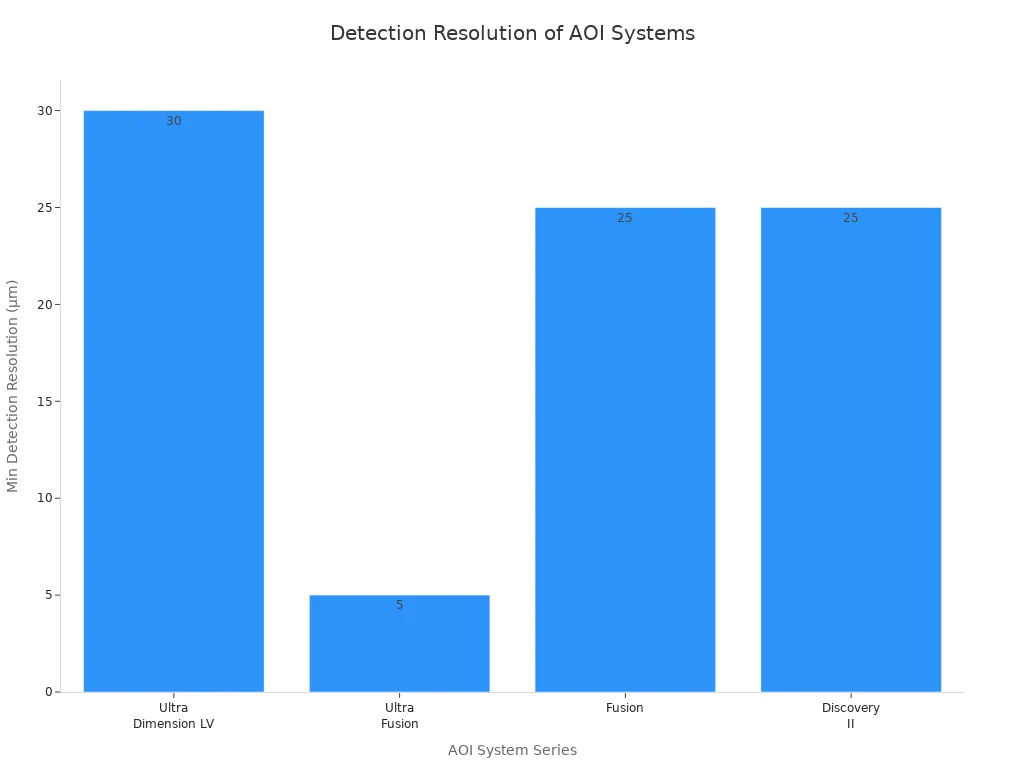
You should also use Automated Optical Inspection (AOI) systems to achieve precise defect detection. AOI systems like Orbotech Ultra Dimension LV and Ultra Fusion™ offer multi-image verification and laser via measurement, reducing false alarms and improving detection accuracy. The table below compares key AOI technologies for flexible automotive electronics:
| AOI System Series | Key Technologies & Features | Application Focus | Detection Resolution / Sensitivity |
|---|---|---|---|
| Orbotech Ultra Dimension LV | 3-in-1 AOI, 2D laser via measurement, multi-image verification | Laser via down to 30μm diameter | 30μm via diameter |
| Orbotech Ultra Fusion™ | Multi-Image™ technology, multi-angle light wavelengths, reduces false alarms by up to 70% | Advanced IC substrates, HDI, flex PCB | Down to 5μm (600P), 10μm (300), 15μm (200) |
| Orbotech Fusion™ | Multi-Image™ technology, red and blue illumination channels, low false alarms | HDI and flex PCB applications | Down to 25μm (Fusion 22, R2R) |
| Orbotech Discovery™ II | SIP™ technology, Smart Setup™, high defect detection, low false alarms | HDI, flex PCB, multi-layer boards, mass production | 25-35μm line and space (various models) |
Tip: Use high-resolution AOI and X-ray inspection to catch microcracks and solder voids that can compromise reliability in automotive electronics.
Environmental Testing
You must conduct environmental testing to verify that flexible circuit boards withstand the harsh conditions found in automotive applications. Environmental tests simulate real-world stresses, helping you identify weaknesses before deployment. The table below summarizes essential environmental tests for automotive flexible electronics:
| Test Category | Specific Test | Purpose | Procedure Summary | Applicable Standards | Typical Failure Modes |
|---|---|---|---|---|---|
| Thermal Testing | Thermal Cycling | Evaluate performance under repeated temperature changes | Cycle PCB between high (+125°C) and low (-40°C) temps for hundreds of cycles | IPC-6013, MIL-STD-202, JEDEC JESD22-A104 | Cracking, solder joint failure, conductor separation |
| Thermal Shock | Assess rapid temperature transitions | Move PCB between extreme hot and cold chambers within seconds | IEC 60068-2-14 | Microcracks in copper traces, adhesive degradation | |
| High-Temperature Aging | Simulate long-term exposure to elevated temperatures | Bake PCB at 85°C–150°C for 168+ hours | IPC-TM-650 2.6.8 | Substrate discoloration, reduced flexibility | |
| Humidity & Moisture | Humidity (Damp Heat) | Evaluate performance in high humidity | 85°C at 85% RH for 500–1000 hours | IPC-TM-650 2.6.3, IEC 60068-2-78 | Swelling, loss of adhesion |
| Pressure Cooker Test | Accelerate moisture penetration | 121°C, 100% RH, 2 atm pressure for 96+ hours | JESD22-A102 | Blistering, electrical leakage | |
| Mechanical Stress | Dynamic Flex | Simulate repeated bending | Bend PCB repeatedly (100,000+ cycles) at defined radius | IPC-6013 (Type 3) | Cracked traces, broken interconnects |
| Static Flex | Check performance when bent and held fixed | Bend PCB to set angle and hold for extended periods | IPC-2223 | Stress fractures, adhesive failure | |
| Chemical Resistance | Chemical Immersion | Assess resistance to solvents, acids, alkalis | Expose PCB to chemicals (e.g., IPA) for 24+ hours | IPC-TM-650 2.3.2 | Discoloration, material degradation |
| Salt Spray | Simulate corrosive marine/automotive environments | Expose PCB to 5% NaCl salt fog for 48+ hours | ASTM B117, IEC 60068-2-52 | Copper corrosion, solder joint failure | |
| Vibration & Shock | Vibration Testing | Ensure survival in high-vibration environments | Subject PCB to random/sinusoidal vibrations (5–2000 Hz) | MIL-STD-810, IEC 60068-2-6 | Broken solder joints, loose components |
| Mechanical Shock | Evaluate resistance to sudden impacts | Apply high-G shocks (e.g., 50G for 11ms) | IEC 60068-2-27 | Fractured traces, component detachment |
You should always test flexible circuit boards for thermal cycling, humidity, vibration, and chemical resistance. These tests help you confirm that your automotive electronics will perform reliably over years of service.
Note: Environmental testing is a critical part of quality testing for automotive flexible electronics. It helps you prevent failures caused by temperature swings, moisture, and vibration.
Traceability
Traceability plays a vital role in maintaining reliability and compliance for automotive flexible circuit boards. You must implement traceability systems that record every step of the manufacturing process. These systems allow you to track each board down to the day of manufacture and every chemical process involved.
You should follow ISO/IATF16949 and PPAP quality assurance systems. These standards require you to document operator details, machine specifications, and manufacturing parameters. You need to maintain full traceability through PPAP level 3 reports and Continuum of Care (COC) reports. Intelligent management systems capture and store all traceability information, ensuring you can quickly identify and address any issues.
Automotive flexible circuit boards must also meet UL and TUV approvals. You need to ensure that your traceability system covers all substrate materials, including flexible and flex-rigid circuits. By following automotive-specific standards like AEC and IPC, you guarantee that your electronics meet the highest reliability requirements.
.png)
.png)
.png)
.png)

.png)

