


 2026-11-09

 BEST
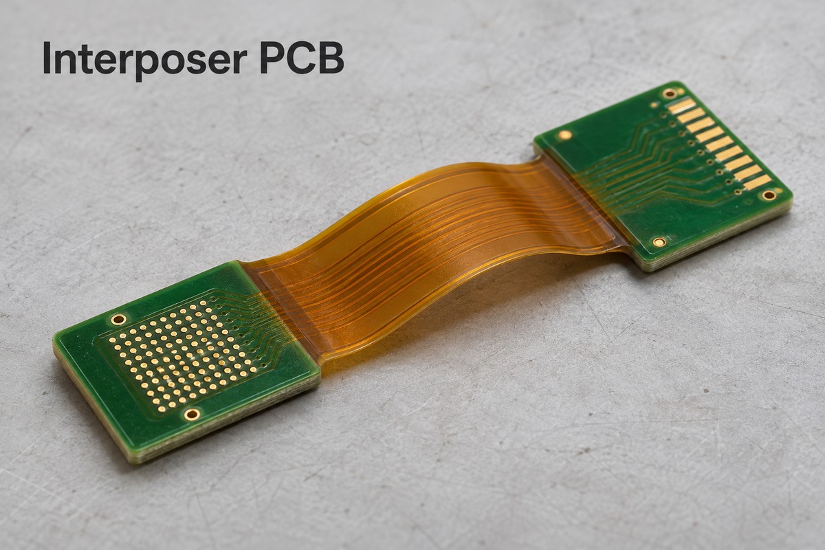
An interposer PCB connects two interfaces whose footprints, pin assignments, or physical positions do not match directly. For compact equipment, a flex or rigid-flex construction can route those connections around an enclosure while providing supported areas for connectors and components.
At BestFPC, we manufacture custom flexible and rigid-flex circuits to your approved drawings, with DFM review and assembly support. Our engineers assess the stack-up, connection areas, and installation requirements together, helping you resolve fabrication issues before production and coordinate bare-board and populated-board requirements. Send your files and quantities to sales@bestfpc.com for a project review and quotation.
What Is an Interposer PCB, and What Can We Manufacture?
An interposer is an intermediate circuit that connects components or boards with different interface layouts. We manufacture custom flex and rigid-flex interposers to your approved design, supplying bare circuits or populated assemblies.
Connection adaptation: PCB traces and vias redistribute signals between specified footprints or pin assignments. Both mating interfaces and the pin map must be defined before fabrication.
Flexible installation: A flexible section can connect modules whose interfaces face different directions or sit at different heights. Specify the installed shape and whether bending occurs only during installation or repeatedly in service.
Supported connection areas: Local stiffeners reinforce contact ends, while rigid-flex construction provides routed rigid sections for connectors and components. The choice depends on the mounting and electrical requirements.
Defined delivery scope: Order bare boards or include component sourcing, assembly, and agreed testing. Identifying the required delivery state helps keep fabrication and assembly responsibilities aligned.
Custom Flex and Rigid-Flex PCB Interposer Options
Choose an interposer board by how its interfaces are supported and positioned. A flexible section is useful when it solves a routing or packaging constraint; it is not automatically necessary for every adapter.
| Construction | Suitable interface arrangement | Main selection check |
|---|---|---|
| FR4 rigid interposer | Fixed, aligned connection points | Footprint and installed clearance |
| Flex with local stiffeners | Offset ends with supported contacts | Finished contact thickness |
| Rigid-flex interposer | Populated rigid sections joined by flex | Transition location and assembly support |
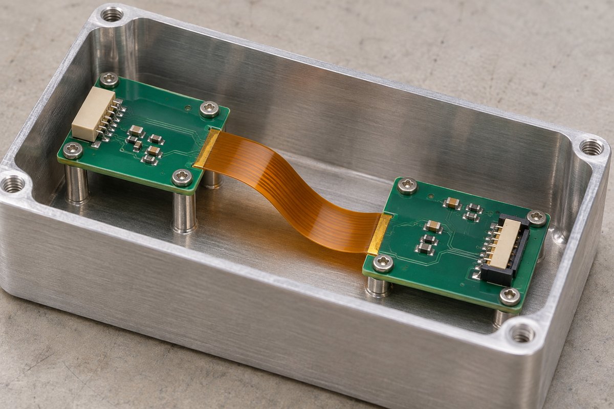
For a PCB to PCB interposer that folds into an enclosure, provide the installed shape as well as the flat outline. A flat drawing alone does not show whether the circuit will pull against a connector or interfere with a housing wall.
Local stiffeners reinforce a flexible circuit but do not create additional routed rigid layers. Choose rigid-flex when the design needs electrically integrated rigid sections for component placement or more complex routing, rather than simply a thicker contact end.
Manufacturing Capabilities for BGA Interposer PCB Projects
A BGA interposer PCB needs a manufacturable path from each required pad to its destination. We assess the pad pattern, routing layers, copper thickness, and via structure together before confirming the build.
The following rigid-flex capabilities provide a starting point for that review:
| Parameter | Standard-process reference | Applicable condition |
|---|---|---|
| Rigid-flex layer count | 2–20 layers | Subject to stack-up review |
| Finished board thickness | 0.3–3.0 mm | Rigid-flex board construction |
| Inner-layer line/space | 3/3 mil | 18 µm finished copper |
| Rigid outer-layer line/space | 3.5/3.5 mil | 18 µm finished copper |
| Impedance tolerance | ±10% | Agreed impedance construction |
Line/space values are before manufacturing compensation and exclude local reduced-feature allowances. Board thickness does not specify the flexible section thickness. These limits must be reviewed as a complete construction, rather than combined into one assumed minimum-feature design.
For dense pad fields, identify the escape-routing bottleneck before adding layers. Pad diameter, clearance, via capture pads, and solder-mask openings all consume space. A stated minimum BGA pad diameter does not establish an allowable ball pitch or prove that the assembly process can handle it.
Interposer PCB Design Review for Interface and Flex Fit
Our interposer PCB design review focuses on whether your supplied layout can be fabricated and assembled within its mechanical and electrical requirements. Include both interface drawings and the installed configuration so the review covers the connection as it will actually be used.
The key review points are:
- Interface mapping: Supply connector part numbers, pin-one orientation, drawing views, and a controlled pin map. Matching contact counts alone cannot establish that the correct nets meet.
- Contact-end thickness: Specify the connector’s permitted insertion thickness. Check the finished flex, adhesive, and stiffener stack together so a nominal stiffener choice does not produce an end that is too thick or too loose.
- Coverlay openings: Identify solderable pads and exposed contacts. Review opening size and registration against nearby conductors so insulation remains where required without obstructing the connection.
- Bend and transition locations: Show the bend direction, available radius, and whether movement is repeated. Keep mounting loads and intended bending away from sensitive terminations and rigid-to-flex transitions through the agreed mechanical layout.
- Signal and return paths: Provide impedance targets and relevant interface requirements. Review reference continuity through the flex section and layer changes; a short adapter still becomes part of the electrical channel.
For PCB interposer design releases, keep the schematic, netlist, fabrication drawing, and panel data on the same revision. A correct individual-board drawing paired with an outdated panel file can still produce the wrong build.
Interposer PCB Assembly and Interface Inspection
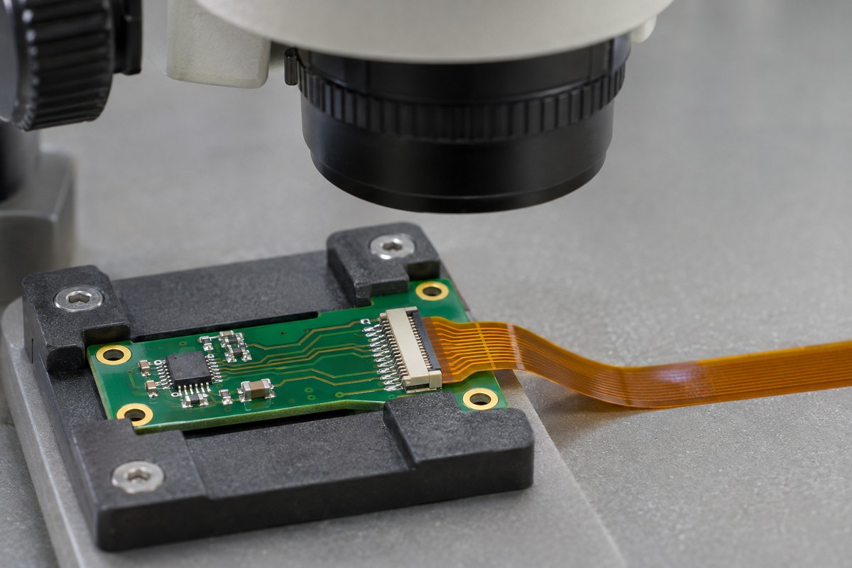
We can coordinate fabrication and assembly requirements for populated interposers, with the inspection scope defined around the actual interfaces. Separate bare-board acceptance from solder-joint inspection and application-level testing when requesting a quote.
Assembly planning should address:
- Support during processing: Identify rigid areas, stiffeners, and fixture contact locations. Thin flexible sections need appropriate support during printing, placement, and reflow to avoid unintended movement.
- Assembly sequence: For parts on both sides, define the build sequence and component thermal requirements. Include connector access and any installation steps that become difficult after the first side is populated.
- Hidden joints: Flag BGA and other inaccessible connections when setting inspection requirements. Agree on suitable inspection methods and acceptance criteria before production, rather than treating a visual check as sufficient.
- Final interface acceptance: Specify which dimensions, electrical connections, and assembled features must be checked. If impedance measurements or a functional fixture are required, include the limits and test responsibilities in the order.
An open/short test checks the manufactured circuit against its netlist. It does not establish that two connected devices have compatible voltage levels, timing, or protocols; those requirements belong in the system validation plan.
Interposer PCB Prototypes, Cost, and Production Orders
Interposer PCB cost depends on the construction and delivery scope, not just the board’s small size. Dense routing, additional lamination steps, special materials, assembly fixtures, and inspection requirements can each change the quotation and schedule.
For prototype orders, distinguish individual pieces from production panels. If the fabrication drawing describes one board while the Gerber and NC drill files describe a panel, state the pieces per panel and the total finished quantity. Also identify who approves panelization and depanelization features.
To obtain a comparable manufacturing quote, provide:
- Released fabrication data: Gerber or ODB++ data, drill files, stack-up, and fabrication drawing, with matching revisions and any special tolerances clearly identified.
- Interface and installation requirements: Mating-part drawings, pin map, finished contact thickness, installed shape, and bend conditions. These establish the constraints that cannot be changed during DFM.
- Assembly and acceptance scope: BOM and placement data for populated boards, plus required inspection reports or customer-supplied testing. State whether the deliverable is bare, assembled, or tested to a specified procedure.
- Order quantities and timing: Prototype quantity, expected repeat-order quantities, and required delivery date. Separate fabrication, assembly, and shipping needs so the proposed schedule covers the complete order.
For US deliveries, confirm the shipping destination and documentation requirements during quotation. Production timing must account for approved manufacturing data, material availability, component procurement where applicable, and the agreed test scope.
Why Choose BestFPC for Custom Interposer Boards?
BestFPC combines engineering support, PCB manufacturing, and PCBA services to help you move a custom interposer from prototype review to repeat production. Our support focuses on the interface details, component choices, and quality requirements that determine whether your design is ready to build.
- Experienced engineering support: Our R&D and PCB/PCBA engineers bring 20 years of experience to DFM analysis and process-adaptation advice. For an interposer, this means reviewing dense connection areas, flex transitions, and assembly constraints together, with proposed changes submitted to your team for approval.
- Actionable DFM and BOM feedback: We provide a DFM pre-review report and a BOM optimization list, giving your engineers specific manufacturing issues and component options to evaluate before release. Proposed substitutions require your approval and a check of footprint, electrical, and application requirements.
- One-stop manufacturing and assembly: We integrate PCB fabrication, component sourcing, PCBA assembly, and agreed testing. Coordinating these stages helps prevent board construction, connector availability, and assembly requirements from being handled as disconnected tasks.
- Prototype and small-batch support: We support sample builds and small production quantities so your team can evaluate interface fit and assembly performance before committing to larger orders. Revision feedback can then be incorporated into the next controlled build.
- Quality-system credentials: Our ISO 9001, ISO 13485, IATF 16949, and AS9100D certifications support supplier qualification for projects with sector-specific quality requirements. Identify the applicable manufacturing scope and required quality documents during quotation so they align with your purchasing specification.
- Digital production traceability: Our digital workshop supports material and product-batch tracking, alongside production-status visibility. This helps connect an interposer build to its manufacturing records when your team needs to investigate a batch or follow an order’s progress.
FAQs about Interposer PCB
1. Interposer vs PCB: how do board-level adapters differ from silicon interposers and IC substrates?
“Interposer” describes an intermediate connection role, while “PCB” describes a circuit-board construction; a board can be both. A silicon interposer is a semiconductor-package structure, and an integrated circuit substrate connects a die or package within its packaging architecture. Our focus here is custom board-level flex and rigid-flex manufacturing, rather than silicon or glass advanced packaging.
2. Can a passive interposer change voltage levels or communication protocols?
No. Passive copper routing can remap connections but cannot perform level shifting or protocol conversion. Where conversion is needed, provide the approved active circuit and components as part of the assembly design.
3. When is an FPC cable sufficient instead of a rigid-flex interposer?
An FPC cable may be sufficient when the task is primarily routing connections between supported endpoints. Rigid-flex becomes relevant when the same assembly also needs routed rigid sections for components or mounting. Compare the complete assembly, including separate boards and connectors, before selecting the construction.
4. Is a compression interposer the same as a flexible PCB?
No. A compression interposer uses a contact system maintained by mechanical compression; a flexible PCB uses patterned conductors on a flexible substrate. They can be parts of the same assembly, but contact force, flatness, and mating requirements must come from the specified contact system. Do not assume that ordering the PCB also includes that system.
5. Can we request a quote with only a sample or an incomplete drawing?
You can send available information for an initial scope discussion. A firm manufacturing assessment needs controlled interface and fabrication requirements; a physical sample alone does not define hidden routing, material construction, or acceptance criteria. Identify the missing files so the required design work is clear before committing to production.
Bring your interface drawings, circuit files, and prototype quantities to BestFPC. Our custom flex and rigid-flex manufacturing supports layouts shaped around your installation, while DFM review helps resolve contact-thickness and transition details before fabrication. With assembly coordination available for populated builds, you can align board construction and final delivery requirements through one project discussion. Email sales@bestfpc.com to request a review and quotation.


.png)
.png)
.png)
.png)

.png)