


 2026-11-06

 BEST
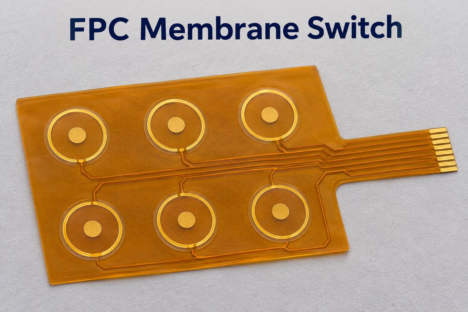
An FPC membrane switch uses an etched copper flexible circuit to connect its switch contacts, tail and any mounted components. This construction is useful when a keypad needs compact routing, soldered LEDs or a connector interface that must fit a defined enclosure. Selecting the circuit means matching its electrical layout to the mechanical stack around it.
At BestFPC, we manufacture custom flex circuits in China for equipment manufacturers and membrane switch integrators. Our fabrication, DFM support and optional component assembly help you source the circuit to match your panel layout and connection requirements. Send your drawings, quantities and assembly scope to sales@bestfpc.com for a review of manufacturing options and a project quotation.
FPC Circuit for Membrane Switch: What We Supply
We manufacture each FPC circuit for membrane switch integration to the approved circuit drawing, supplying bare circuits or assembled FPCs to suit your project.
- Custom circuit fabrication: We produce the copper circuit, contact pads and connection tail to your specified outline and stack-up.
- Optional component assembly: We can supply the FPC with LEDs and other specified components mounted, based on your BOM and assembly files.
- Panel interface coordination: For an FPC circuit for graphic overlay membrane switch applications, provide common datums for key positions, contact centers and mounting features so the circuit aligns with the panel.
FPC membrane switches may also include overlays, spacers and metal domes. Identify which parts your panel integrator will supply so the quotation clearly defines our circuit delivery scope.
Flexible Membrane Switch: PET Silver Ink vs. Copper FPC
A flexible membrane switch can use printed silver-ink circuitry on PET or etched copper circuitry on polyimide. Copper flex circuits are worth evaluating when routing density, soldered components or the tail connection makes a printed circuit less suitable.
| Selection factor | PET silver-ink circuit | Copper FPC |
|---|---|---|
| Conductor formation | Printed conductive ink | Etched copper |
| Component attachment | Conductive adhesives or suitable alternatives | Soldering with a qualified assembly process |
| Routing | Printed traces and crossover structures | Copper traces, vias and multiple layers |
| Cost drivers | Print passes, tooling and layout | Layer count, copper processing and features |
| Typical fit | Simpler switch matrices | Integrated circuitry and component mounting |
Neither construction is automatically the lower-cost choice for every keypad. Compare the complete circuit and assembly requirements: adding layers, finer features or special finishes to an FPC can outweigh savings elsewhere in the panel.
FPC Membrane Switch Customization and Manufacturing Options
FPC membrane switch customization starts with the switch matrix, mounting space and connection method. We use these inputs to define the circuit construction and review whether the selected materials suit fabrication and assembly.
- Layer arrangement: Use the routing requirements to decide whether a single-sided circuit is sufficient or whether a second copper layer is needed for crossings and connections.
- Contact and soldering areas: Identify which exposed pads serve switching, connector mating or component soldering. Their surface requirements may differ.
- Local support: Add reinforcement where the circuit needs insertion support or a stable mounting surface, while keeping the intended bend section flexible.
- Mounting adhesive: Define the adhesive coverage and keep-out areas around exposed contacts, assembly features and the tail.
Specify these functional regions on the fabrication drawing. A single overall thickness or a general note such as “gold finish” leaves too much uncertainty at the interfaces.
Manufacturing Capabilities for Custom Flex Circuits
Our standard flex fabrication options include one to four copper layers, polyimide constructions and local PI reinforcement. The following options provide a starting point for a membrane switch circuit quotation.
| Manufacturing item | Available options |
|---|---|
| Copper layers | 1–4 |
| Flex board thickness | 0.06–0.60 mm |
| Adhesive-based core PI | 0.5, 1 or 2 mil |
| Adhesiveless core PI | 0.5, 1, 2 or 3 mil |
| Adhesiveless core copper | 0.33, 0.5, 1 or 2 oz |
| PI stiffener thickness | 3, 5, 7 or 9 mil |
| Surface finishes | ENIG, electroplated gold, OSP, tin plating |
| Outer-layer line/space at 18 µm finished copper | 3.5/3.5 mil before compensation |
These are individual process options, not a promise that every combination shares the same minimum dimensions. Final stack-up, finished thickness and feature limits are reviewed together.
For connector tails, specify the finished reinforced thickness separately from the PI stiffener material thickness. Adhesive and the underlying flex construction also contribute to the dimension that enters the connector.
Contact, Tail and Stiffener Requirements for Membrane Switch Circuits
A custom FPC membrane switch design needs defined contact geometry, a matched tail interface and reinforcement that supports assembly without obstructing the bend area. These details should be reviewed before the circuit artwork is released.
- Contact geometry: Use the selected dome supplier’s footprint and support requirements. For dome switches, check the exposed contact area, coverlay clearance and alignment with the actuator.
- Tail interface: State the pin assignment, contact pitch, exposed-contact length, insertion direction and contact side. Match the finished thickness to the selected connector specification.
- Stiffener boundary: Locate reinforcement relative to the connector and enclosure. Keep repeated bending away from abrupt stiffness transitions and define the intended bend region.
- Mechanical references: Dimension contacts, holes and the tail from consistent datums. Avoid relying on separate overlay and circuit drawings with unrelated origins.
Our DFM review focuses on how the supplied design can be manufactured. The approved keypad layout, electrical function and mating-part specifications remain essential inputs.
FPC Assembly for LEDs and Other Components
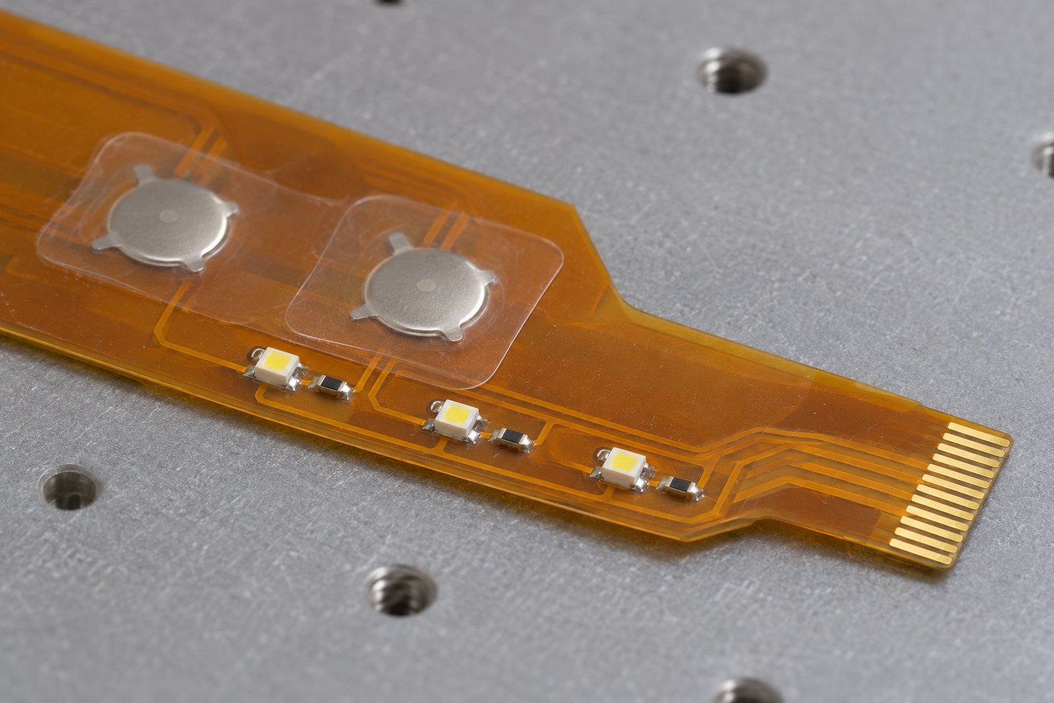
We provide component assembly for switch circuits that include LEDs and other electronic parts. The assembly plan addresses component fit, flexible-board handling and the delivery format required for panel integration.
- Placement and polarity: Supply the BOM, component coordinates and orientation details so each part matches the intended electrical layout.
- LED and panel alignment: SMD LEDs on the FPC circuit must align with the light windows. Check component height against the overlay and spacer clearance.
- Assembly support: Panelization and support tooling must hold the flexible substrate during printing, placement and reflow, with populated areas kept outside the intended bend region.
- Delivery format: Specify panelized or separated circuits so handling and integration requirements can be considered before assembly.
Inspection and Testing for Membrane Switch FPCs
The circuit inspection plan should verify electrical connectivity and the dimensions that control panel integration. For assembled FPCs, component inspection and any specified functional checks extend that plan.
- Electrical continuity and isolation: Check the manufactured circuitry against the intended net connections for opens and shorts.
- Contact areas: Inspect exposed pad geometry, coverlay registration and the specified surface condition.
- Mechanical fit: Check the outline, locating features, tail dimensions and reinforced thickness against drawing tolerances.
- Assembled components: Inspect placement, polarity and solder joints; define functional testing through an agreed procedure and acceptance limits.
Switch actuation force, sealing and operating life depend on the completed assembly. Their acceptance criteria belong in the finished switch test plan rather than being inferred from an FPC electrical test.
Custom Membrane Switch with FPC Circuit: A Manufacturing Case Study
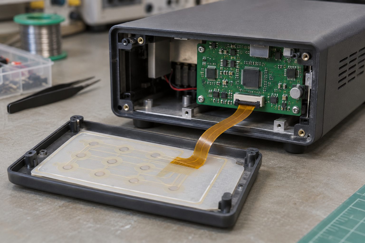
A custom membrane switch with FPC circuit can provide the electrical interface for an instrument’s front-panel keypad, connecting operator inputs to the control electronics. Our two-layer membrane FPC construction below suits this application: a thin circuit fits beneath the panel, backing adhesive supports attachment, and local PI reinforcement provides support where the assembly needs it.
The manufacturing challenge is to accommodate these different mechanical roles within one circuit without treating every region as the same thickness.
- Fitting beneath the keypad: Use the thin adhesiveless PI circuit as the flexible base, then control the finished adhesive-backed thickness against the panel stack-up. This helps the integrator allocate space for the circuit, spacer and overlay.
- Supporting the interface locally: Apply PI reinforcement only in the drawing-defined support region. Control its total finished thickness separately, and position its boundary clear of the intended bend area so the supported interface does not make the entire circuit unnecessarily stiff.
- Aligning the circuit with the panel: Check the artwork, adhesive openings and reinforced areas against the mechanical drawing before release. This project required customer approval of the production stack-up and artwork, providing a review point for the features that determine mounting and connection fit.
| Circuit feature | Project specification |
|---|---|
| Circuit layers | 2 |
| Copper construction | 1/3 oz rolled-annealed copper + 6 µm plating |
| Core dielectric | 1 mil adhesiveless PI |
| Coverlay | 1/2 mil, yellow |
| Backing adhesive | 60 µm 3M 467 |
| Bare circuit thickness | 0.10 ± 0.03 mm |
| Circuit plus PI reinforcement | 0.30 ± 0.03 mm |
| Circuit plus backing adhesive | 0.17 ± 0.05 mm |
| ENIG gold / nickel thickness | 0.03–0.08 µm / 2–6 µm |
For the equipment designer, the value is a circuit construction that combines a thin panel layer, a defined bonding interface and local mechanical support. Specifying these regions separately makes the assembly requirements clearer for both fabrication and final keypad integration.
FPC Circuit for Custom Membrane Switch: Cost, Lead Time and RFQ
The cost of an FPC circuit for custom membrane switch projects depends on its outline, panel utilization, layer structure, contact finish and assembly scope. Lead time is quoted against the approved construction, material availability, quantity and any component sourcing requirements.
A narrow circuit with a long tail can use panel space differently from a compact rectangular board. Custom adhesive shapes, reinforcement placement and additional assembly operations also affect the production route, so dimensions alone are not enough to estimate price.
For a useful quotation, send:
- Fabrication data: Gerber files, drill data, outline drawing, stack-up and finished-thickness tolerances.
- Interface requirements: Contact details, connector specification, tail pinout, reinforcement and adhesive drawings.
- Assembly files: BOM, placement data and component orientation when a populated circuit is required.
- Order scope: Prototype and production quantities, delivery format, inspection requirements and requested delivery date.
For customers importing into the USA, include the destination and distinguish the required shipment date from the required arrival date. This keeps manufacturing scheduling and transit planning separate.
Why Choose BestFPC for Your Membrane Switch Circuit?
BestFPC combines custom flex fabrication, manufacturing review and optional component assembly to help you source a circuit that fits your panel and connection requirements.
- Manufacturing feedback before release: Our DFM support reviews the supplied construction and interface requirements, helping you resolve fabrication questions before production.
- Coordinated fabrication and assembly: We review board construction and assembly files together, so component support, panelization and delivery format are considered as part of the same build.
- Prototype and small-batch support: You can evaluate circuit fit and assembly compatibility during development before committing to production quantities.
- Quality system certifications: Our qualifications include ISO 9001, ISO 13485, IATF 16949 and AS9100D. We can provide the relevant certification information for your supplier qualification review.
- Dedicated engineering coordination: Our technical team supports your project from enquiry through delivery, helping clarify contact geometry, tail interfaces and assembly requirements as your design progresses.
- Production traceability: Our digital workshop supports tracking of material and product batches alongside production progress, helping you investigate quality issues and coordinate subsequent builds.
Frequently Asked Questions About Membrane Switch Circuits
Does an FPC make a membrane switch waterproof?
No. A waterproof FPC membrane switch requires suitable sealing around the overlay, edges, tail exit and enclosure interface. The FPC substrate alone does not establish a protection rating; validate the completed assembly to the required test conditions.
How is the operating temperature range determined?
Evaluate the complete material stack, including adhesives, overlay, contacts and mounted components. Polyimide’s heat resistance or a brief soldering temperature does not establish the continuous operating temperature of the finished switch.
Is ENIG equivalent to hard gold for repeated contact wear?
No. ENIG and wear-oriented electroplated gold systems have different structures and purposes. Select the contact finish using the mating material, contact movement and service requirements, then specify the relevant plating properties.
Can the FPC tail bend repeatedly during use?
Only when the circuit is designed for that motion. Define bend radius, movement, cycle requirements and the location of reinforcement and components. A tail that bends once during installation should not automatically be treated as a dynamic flex circuit.
Can a PET circuit drawing be used directly to order a copper FPC?
It needs a manufacturing review first. Replacing printed conductors with etched copper can change routing, crossover construction, thickness and termination details. Keep the electrical function and mechanical interfaces as the reference while reviewing the new circuit construction.
Can carbon contact areas be included?
If carbon contacts are required, provide their geometry, resistance limits, mating contact and wear requirements for a separate process review. Do not substitute a metal finish without checking its compatibility with the intended contact system.
BestFPC can help you define the fabrication and assembly scope for your next membrane switch circuit. Your project is supported by a dedicated account manager and a multidisciplinary engineering team, providing coordinated support for contact geometry, tail interfaces and assembly requirements from enquiry through delivery. Our engineers with 20 years of PCB/PCBA experience provide a DFM pre-review report and process recommendations, with BOM optimization suggestions for circuits that include LEDs or other components. Send your drawings and quantity requirements to sales@bestfpc.com for a manufacturing review and quotation.


.png)
.png)
.png)
.png)

.png)