


 2026-11-17

 BEST
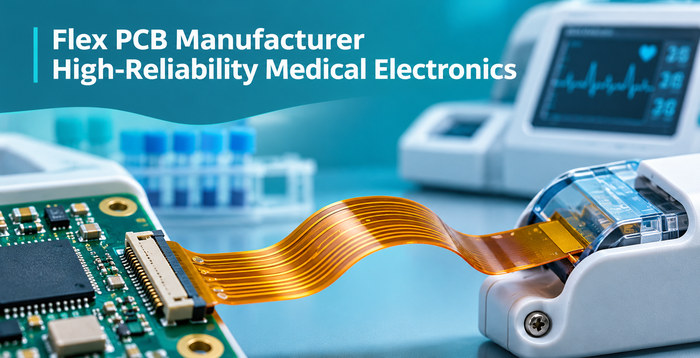
A qualified flex PCB manufacturer for high-reliability medical electronics must deliver more than precision circuit fabrication. Medical OEMs also require consistent material quality, tight dimensional control, and reliable manufacturing processes. BestFPC operates under an ISO 13485-certified quality management system and provides custom flexible PCB manufacturing, prototyping, and volume production services for medical diagnostic equipment, patient monitoring systems, and precision medical electronics.
Are you struggling with cracked copper traces, unreliable connector contacts, inconsistent FPC thickness, or repeated prototype revisions? These problems can delay medical device validation, cause assembly defects, and increase rework costs. Choosing suitable materials, manufacturing processes, and a qualified supplier can help reduce these risks before production begins.
Where Are High-Reliability Flex PCBs Used in Medical Electronics?
High-reliability medical flex PCBs are widely used in equipment requiring compact electrical connections, stable signal transmission, and mechanical flexibility. Their construction depends on the available installation space, bending frequency, and reliability requirements.
-
Wearable Patient Monitoring Devices: ECG monitors, portable physiological sensors, and medical monitoring patches use thin flexible circuits to connect sensors and electronic modules. These applications require compact structures and resistance to mechanical stress during operation.
-
Portable Diagnostic Equipment: Blood glucose meters, point-of-care testing instruments, and handheld diagnostic devices require precise connector dimensions and reliable electrical interconnections within limited spaces.
-
Medical Imaging Equipment: Ultrasound probes and compact imaging modules use flexible circuits for high-density signal routing, where trace accuracy, impedance control, and signal integrity are important.
-
Surgical and Endoscopic Instruments: Narrow or curved instrument structures require thin flexible interconnections with controlled thickness, bending geometry, and electrical insulation.
-
Medical Testing and Sensor Systems: Diagnostic analyzers and medical sensor modules use customized FPCs to connect sensing elements, control circuits, and internal interfaces.
Static and dynamic bending requirements must be distinguished. A flex PCB that remains stationary after installation has different material and fatigue requirements from a circuit that bends repeatedly during device operation.
What Are the Key Design Requirements for High-Reliability Medical Flex PCBs?
Medical flex PCB design must address bending stress, conductor geometry, connector accuracy, and electrical performance. These factors determine whether the circuit can maintain reliable connections after installation and throughout its intended operating life.
-
Bend Radius and Flex Life: Define the installed bend radius, bending direction, movement frequency, and required bending cycles. Dynamic flex areas should minimize stress concentration and keep plated holes and stiffener edges away from repeated bending regions.
-
Trace Width and Spacing: Conductor dimensions must meet current-carrying, signal integrity, and manufacturing requirements. Fine-pitch circuits require controlled etching to prevent excessive conductor narrowing or insufficient insulation spacing.
-
Copper Thickness: Common flexible circuit copper thicknesses include approximately 12, 18, and 35 μm. Thinner copper generally improves flexibility, while higher-current applications may require thicker conductors.
-
Via and Pad Placement: Plated through-holes, solder pads, and abrupt trace-width transitions should be avoided in dynamic bending areas to reduce fatigue cracking and connection failures.
-
Connector Accuracy: ZIF and other FPC connectors require precise contact pitch, contact length, finished insertion thickness, and reinforcement to maintain stable electrical connections.
-
Signal Integrity and Insulation: Medical sensor and imaging circuits may require controlled impedance, suitable grounding, and specified dielectric properties to minimize signal loss and interference.
For medical FPCs exposed to repeated bending, the complete stackup, copper position, and actual operating conditions must be evaluated together. Bend life cannot be determined from nominal substrate thickness alone.
Which Materials Are Suitable for Medical Flexible PCBs?
Polyimide substrates, suitable copper foils, flexible coverlay, and localized stiffeners are commonly used in medical flex PCB manufacturing. Material selection should account for circuit complexity, bending requirements, operating temperature, and connector construction.
-
Polyimide (PI) Substrate: PI offers flexibility, thermal resistance, and electrical insulation. Common core thicknesses include 12.5, 25, and 50 μm.
-
Rolled Annealed (RA) Copper: Frequently selected for dynamic flex applications because suitable RA copper constructions generally provide better resistance to repeated bending fatigue.
-
Electrodeposited (ED) Copper: Suitable for many static flex applications where the circuit is bent during installation and remains relatively stationary afterward.
-
Adhesiveless Polyimide Laminate: Eliminating the adhesive layer between copper and the PI core can reduce overall thickness and improve flexibility, making it useful for thin medical interconnections.
-
Polyimide Coverlay: Protects conductors and provides electrical insulation while leaving specified connector contacts and solder pads exposed.
-
PI or FR4 Stiffeners: Reinforce connector tails and mounting areas. Stiffener thickness must be selected according to the finished connector insertion requirements.
Single-layer FPCs suit relatively simple sensor interconnections, while double-layer FPCs provide additional routing space. Multilayer flexible circuits accommodate more complex electrical connections but generally increase bending stiffness.
For medical devices requiring rigid component-mounting sections and flexible interconnections within the same circuit, a rigid-flex PCB may be more suitable.
What Manufacturing Challenges Affect Medical Flex PCB Reliability?
Copper cracking, delamination, fine-line defects, plated-hole failures, and dimensional variation are major manufacturing challenges in medical flex PCBs. These defects can cause intermittent electrical connections, device malfunction, or assembly rejection.
-
Copper Cracking: Excessive bending stress, unsuitable copper construction, and abrupt trace-width transitions can cause fatigue fractures. Appropriate copper selection, controlled conductor geometry, and suitable bend-region layouts help reduce this risk.
-
Layer Delamination: Moisture absorption, poor material compatibility, or unstable lamination conditions can weaken bonding between layers. Controlled material preparation and lamination improve structural integrity.
-
Fine-Line Defects: Over-etching and imaging deviations can reduce conductor width or insulation spacing. Controlled pattern formation and AOI inspection help identify these defects.
-
Plated-Hole Failures: Inadequate drilling or copper deposition can compromise interlayer connections. Hole preparation, plating control, and electrical testing help verify interconnection quality.
-
Dimensional Instability: PI materials may change dimensions during thermal processing. Process compensation and dimensional inspection help maintain connector positions and board outlines.
-
Connector Contact Problems: Misaligned coverlay openings, unsuitable surface finishes, or incorrect stiffener thicknesses can affect connector mating and contact stability.
For medical OEM projects, manufacturing risks do not end after prototype approval. Consistent material specifications, controlled production files, and defined acceptance requirements are essential for maintaining quality across subsequent production batches.
What Is the Manufacturing Process for High-Reliability Medical Flex PCBs?
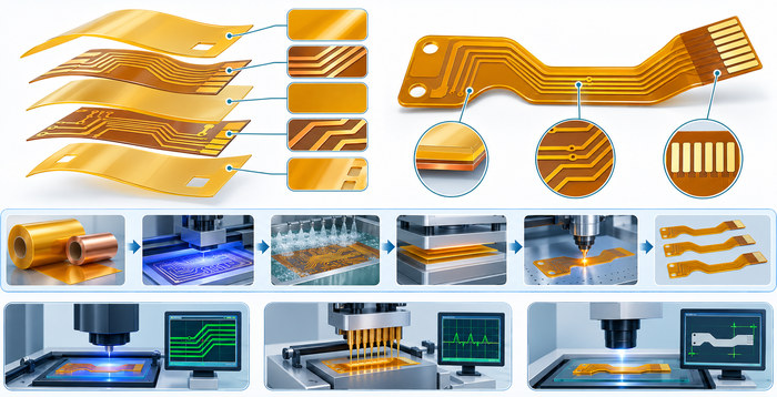
Medical flex PCB manufacturing typically involves DFM review, material preparation, circuit fabrication, coverlay lamination, surface finishing, and final inspection. Double-sided and multilayer constructions also require interlayer connection processing.
-
DFM Review and Material Verification: Review Gerber files, fabrication drawings, stackups, PI thickness, copper specifications, connector dimensions, and critical tolerances to confirm manufacturing feasibility.
-
Drilling and Interlayer Processing: For applicable double-sided and multilayer circuits, perform drilling, hole-wall preparation, metallization, and plating. Hole positioning and interlayer electrical continuity are controlled throughout processing.
-
Circuit Imaging and Etching: Form conductor patterns through photolithography and etching, followed by inspection for trace-width deviations, spacing defects, opens, and shorts.
-
Coverlay Lamination: Prepare coverlay openings for solder pads and connector contacts, then complete lamination with controlled alignment and bonding conditions.
-
Surface Finishing and Stiffener Attachment: Apply the specified surface finish, such as ENIG or gold plating, and bond PI or FR4 stiffeners to designated connector or mounting areas.
-
Profiling and Final Inspection: Complete the board outline using the approved fabrication method, followed by dimensional inspection, electrical continuity testing, and insulation testing. Additional inspections are performed according to project requirements.
Why Choose BestFPC as Your Flex PCB Manufacturer for High-Reliability Medical Electronics?
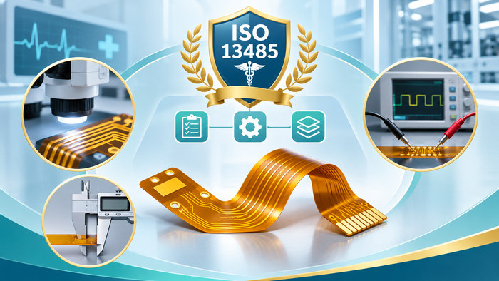
BestFPC combines precision flexible PCB manufacturing, ISO 13485-certified quality management, material processing capabilities, and prototype-to-production support. For medical OEMs, these capabilities help maintain manufacturing consistency, reduce avoidable defects, and simplify supplier coordination.
-
ISO 13485 Certification Supports Medical Supplier Qualification: BestFPC's quality management system supports controlled manufacturing documentation and applicable traceability requirements. Medical OEMs can request relevant certification and quality records during supplier evaluation, helping reduce uncertainty in supplier qualification.
-
Precision FPC and Rigid-Flex Manufacturing Supports Complex Designs: Manufacturing capabilities for thin flexible circuits, fine-pitch routing, and integrated rigid-flex structures allow customers to select suitable constructions for compact medical electronics.
-
Free DFM Check Helps Reduce Rework Costs: BestFPC reviews stackups, trace spacing, bending regions, coverlay openings, vias, and stiffener structures before fabrication. Potential manufacturing problems can be identified before they lead to repeated prototype revisions.
-
Direct Manufacturing Improves Communication and Production Coordination: BestFPC operates flexible PCB manufacturing facilities, allowing customers to communicate manufacturing requirements, fabrication concerns, and production schedules directly with the manufacturer.
-
Prototype and Volume Production Support Reduces Supplier Transition Risks: Customers can move from initial samples to small-batch and repeat production using approved manufacturing files and specifications, reducing the work involved in qualifying another supplier.
-
Inspection and Quality Documentation Support Customer Acceptance: Circuit inspection, electrical testing, dimensional verification, and agreed quality records help medical OEMs establish clear incoming inspection and acceptance requirements.
For projects where dimensional accuracy, mechanical reliability, and production consistency are critical, BestFPC provides manufacturing capabilities and quality management support that help reduce production uncertainty.
What Custom Medical Flex PCB Manufacturing Services Does BestFPC Offer?
BestFPC provides custom bare flexible PCB fabrication, rigid-flex PCB manufacturing, specialized material processing, and prototype-to-volume production services. Customers can specify the required construction according to their approved drawings and product requirements.
-
Custom Flexible PCB Fabrication: Single-sided, double-sided, and multilayer FPC manufacturing for special outlines, thin structures, and precision connection areas.
-
Rigid-Flex PCB Manufacturing: Integrated rigid and flexible constructions for medical electronics requiring rigid component-mounting sections and flexible interconnections.
-
Custom Materials and Special Processes: Specified PI laminates, coverlay processing, localized reinforcement, surface finishing, and HDI structures compatible with the selected manufacturing process.
-
Prototype, Small-Batch, and Volume Production: Manufacturing based on approved fabrication files, material specifications, acceptance criteria, and order quantities.
What Are BestFPC's Medical Flex PCB Manufacturing Capabilities?
BestFPC supports 1–4-layer standard flexible PCB manufacturing and 2–20-layer rigid-flex PCB fabrication. The manufacturing specifications differ according to whether the product requires a fully flexible circuit or an integrated rigid-flex structure.
Standard Flexible PCB Manufacturing Capabilities
| Manufacturing Parameter | Standard Capability |
|---|---|
| Flex PCB Layer Count | 1–4 layers |
| Finished Flex Board Thickness | 0.06–0.60 mm |
| Minimum Inner-Layer Line/Space | 3/3 mil |
| Minimum Outer-Layer Line/Space | 3.5/3.5 mil |
| Minimum Mechanical Drill Diameter | 0.15 mm |
| Adhesive-Based PI Core Thickness | 0.5, 1, 2 mil |
| Adhesiveless PI Core Thickness | 0.5, 1, 2, 3 mil |
| PI Stiffener Thickness | 3, 5, 7, 9 mil |
| Surface Finishes | ENIG, gold plating, OSP, tin plating |
| Impedance Tolerance | ±10% for applicable constructions |
Rigid-Flex PCB Manufacturing Capabilities
| Manufacturing Capability | Standard Process | Advanced Process |
|---|---|---|
| Rigid-Flex Layer Count | 2–20 layers | 2–20 layers |
| Flex Layer Position | Outer or middle layers | Outer or middle layers |
| Finished Board Thickness | 0.3–3.0 mm | 0.3–3.0 mm |
| Board Thickness Tolerance | ±0.1 mm (≤1.0 mm); ±10% (>1.0 mm) | Same as standard |
| Minimum Flex Width | 2.0 mm | 2.0 mm |
| Maximum Finished Board Size | 210 × 1,000 mm | 210 × 1,100 mm |
| Minimum Inner-Layer Line/Space | 3/3 mil | 2.5/2.5 mil |
| Minimum Rigid Outer-Layer Line/Space | 3.5/3.5 mil | 3/3 mil |
| Minimum Flex Outer-Layer Line/Space | 5/4.5 mil | 5/4.5 mil |
| Laser Via Diameter | 3–4 mil | 2–3 mil |
| HDI Structure | 1+n+1 | 2-step / 3-step HDI |
| Impedance Tolerance | ±10% | ±10% |
| Minimum Conductor-to-Rigid/Flex Junction Clearance | 0.3 mm | 0.2 mm |
| Flexible Core Materials | Adhesive and adhesiveless PI | Specified Panasonic RF and DuPont AP materials |
| Surface Finishes | ENIG, gold plating, OSP, tin plating | Standard finishes plus ENEPIG |
For rigid-flex PCBs, the 0.3–3.0 mm finished thickness refers to the overall board construction rather than the thickness of the flexible section. Fine-line routing, laser vias, and HDI structures must be evaluated together with the required copper thickness, dielectric construction, and interlayer connections.
Case Study: Two-Layer Flex PCB Prototyping and Small-Batch Production
Project Background
A customer developing an electronics product required two-layer flexible PCBs, beginning with prototype fabrication and progressing to small-batch production. The customer needed a supplier capable of supporting both stages without disrupting communication or manufacturing coordination.
Project Requirements
The project involved the following manufacturing and delivery requirements:
-
PCB Construction: Two-layer flexible PCB.
-
Production Stages: Initial prototype manufacturing followed by small-batch orders.
-
Manufacturing Consistency: Continued production according to the customer's approved requirements.
-
Supplier Support: Timely responses and consistent communication throughout product development and production.
The customer needed stable manufacturing support to maintain continuity between prototype validation and subsequent production.
Manufacturing Challenges and Solutions
The primary challenge was maintaining a smooth transition from prototype validation to small-batch manufacturing without introducing unnecessary supplier changes or repeated production coordination.
BestFPC initially supported the customer's two-layer FPC prototype requirements and subsequently continued with small-batch production. Both stages were handled through the same supplier, maintaining continuity in technical communication and production coordination.
Project Results
BestFPC successfully completed the two-layer FPC prototype order and subsequent small-batch production, meeting the customer's manufacturing and delivery requirements.
By supporting both production stages, BestFPC maintained consistent manufacturing specifications, streamlined project communication, and ensured a smooth transition from prototyping to small-batch manufacturing.
This project demonstrates BestFPC's capability to support flexible PCB prototyping, small-batch production, and reliable manufacturing coordination.
What Is the Lead Time for Custom Medical Flex PCBs?
Medical flex PCB lead time depends on layer count, material availability, manufacturing complexity, and inspection requirements. BestFPC offers the following typical mass-production lead time ranges for eligible standard flexible PCB constructions:
-
1-Layer Flex PCB: Standard production approximately 1.5–2 weeks; expedited production approximately 1 week.
-
2-Layer Flex PCB: Standard production approximately 2–2.5 weeks; expedited production approximately 1 week.
-
3-Layer Flex PCB: Standard production approximately 2.5–3 weeks; expedited production approximately 1.5 weeks.
-
4-Layer Flex PCB: Standard production approximately 3–4 weeks; expedited production approximately 1.5 weeks.
HDI rigid-flex structures, special PI materials, complex processing, and additional reliability qualification may require longer manufacturing schedules.
To reduce avoidable delays, provide finalized Gerber files, approved stackup information, order quantities, inspection requirements, and the target delivery date before production release. International shipping time should be considered separately from fabrication lead time.
FAQs About Medical Flex PCB Manufacturing
Q1: Does ISO 13485 certification mean a medical flex PCB has received medical device regulatory approval?
A1: No. ISO 13485 is a quality management system standard for medical-device-related organizations. Certification does not mean that an individual PCB or finished medical device has received regulatory approval. Applicable device-level validation and regulatory compliance remain separate requirements.
Q2: Is IPC Class 3 mandatory for every medical flexible PCB?
A2: No. The appropriate IPC acceptance class depends on the device's reliability requirements and the customer's specified standards. High-reliability applications may require IPC Class 3, but it is not automatically mandatory for every medical flexible PCB.
Q3: Can medical flex PCBs withstand steam or chemical sterilization?
A3: Sterilization compatibility must be verified for the actual material construction and sterilization process. Steam, chemical exposure, and radiation may affect PI substrates, adhesives, coverlay, and surface finishes differently. Material heat resistance alone does not confirm sterilization compatibility.
Q4: Can ENEPIG be used on standard flexible PCBs?
A4: ENEPIG is included in BestFPC's advanced rigid-flex manufacturing options. Its availability for a particular all-flex construction requires confirmation of the material structure, surface finish requirements, and applicable fabrication process.
Q5: How are thin medical flex PCBs and connector contacts protected during shipping?
A5: Depending on the order requirements, protective packaging may include antistatic materials, separation layers, and packaging arrangements that prevent excessive bending. Precision connector contacts should be protected against scratches, contamination, and permanent creasing during transportation.
Q6: Can BestFPC sign an NDA before receiving confidential medical device design files?
A6: Yes. Confidentiality arrangements can be discussed before proprietary Gerber files, product drawings, material specifications, or other technical documents are exchanged. The NDA can define the scope of confidential information, permitted use, and confidentiality period.
Q7: Can I request a preliminary medical flex PCB quotation before the Gerber files are complete?
A7: Yes. Available drawings, layer count, finished thickness, material requirements, estimated quantity, and delivery location can be submitted for preliminary evaluation. A final manufacturing quotation generally requires complete circuit patterns, drill information, and critical fabrication dimensions.
Q8: What happens if a material substitution is required during medical flex PCB production?
A8: Material substitutions should be approved by the customer before implementation. Alternative materials must be evaluated for substrate thickness, copper type, adhesive construction, dielectric properties, and mechanical performance. Changes should follow the agreed approval process to avoid affecting the validated product construction.
Are cracked copper traces, connector-fit problems, or inconsistent production quality causing repeated prototype revisions in your medical electronics project? Unsuitable materials, unexpected manufacturing limitations, and dimensional defects can lead to assembly failures, delayed validation, and missed production schedules.
BestFPC provides ISO 13485-certified quality management support, precision medical flex PCB manufacturing, customized material processing, and prototype-to-volume production services. With a free DFM check, we can help identify manufacturing risks before fabrication, reduce unnecessary rework, and manufacture flexible PCBs according to your approved specifications.
Send your Gerber files, technical specifications, required quantity, and target delivery date to sales@bestfpc.com to request a free DFM check and customized quotation for your medical flex PCB project.


.png)
.png)
.png)
.png)

.png)