


 2026-10-28

 BEST
An ECG PCB needs to fit the device, preserve the intended signal paths, and remain consistent as the design moves into production. For US medical OEMs developing portable monitors, wearable patches, Holter recorders, or patient monitoring systems, the right manufacturing partner helps resolve board construction and assembly details before they become expensive revisions.
For US teams, a successful build starts with engineers who understand how an ECG board must fit, connect, and reach production. At BestFPC, our China-based team draws on long-term medical customer relationships and experienced engineering and quality leadership to resolve stackup, bend-zone, and connector questions within a controlled manufacturing process. Send your drawings to sales@bestfpc.com for practical feedback before committing to a build.
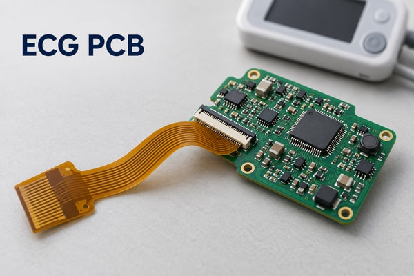
ECG PCB Circuit Fabrication for US Medical Devices
Our ECG PCB circuit fabrication covers custom flexible circuits and rigid-flex boards for device interconnections and compact electronic assemblies. Our standard capabilities include 1–4-layer all-flex PCBs and 2–20-layer rigid-flex PCBs, with the construction selected around your circuit layout, component locations, and mechanical drawing.
- Portable ECG monitors: A flexible connection between the acquisition board and display.
- Wearable ECG patches: Supported component areas joined by thin flexible sections.
- Holter recorders and patient monitors: An FR4 acquisition board with separate interconnects where that arrangement suits the device.
We start with the physical layout rather than assuming every ECG project needs rigid-flex.
For fabrication, identify the board outline, layer stackup, exposed contacts, reinforced areas, and critical dimensions. If assembly is included, the BOM and placement files let us address component sourcing, board support, and inspection alongside fabrication. This brings the mechanical and manufacturing decisions together before tooling begins.
Flexible vs. Rigid-Flex PCB for ECG Monitors
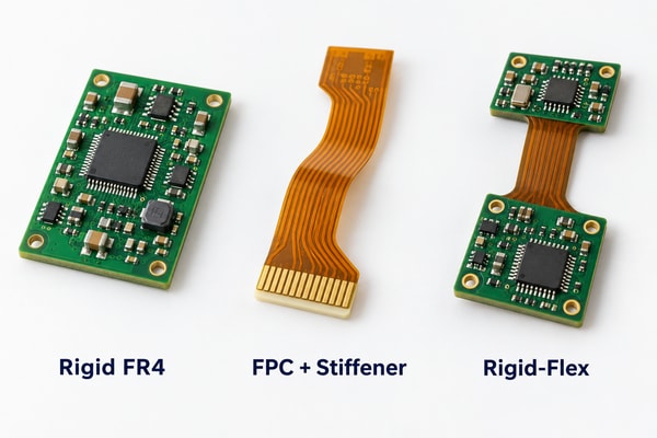
Use rigid FR4 when the electronics can remain on a supported, flat board; use flex where the connection must bend; consider rigid-flex when integrating those sections removes a meaningful assembly constraint. The enclosure and connection layout should drive the choice.
| PCB Construction | Suitable ECG Application | Main Advantage |
|---|---|---|
| Rigid FR4 | ECG acquisition and processing boards | Stable component mounting |
| FPC with stiffeners | Wearable patches and flexible connections | Thin, flexible routing |
| Rigid-Flex PCB | Compact integrated monitoring modules | Fewer separate connectors |
Understand the construction. A stiffened FPC and a rigid-flex PCB are different constructions. A bonded stiffener adds local mechanical support; it does not add routed rigid circuit layers. A rigid-flex PCB design integrates rigid circuit sections with flexible layers in one board.
Compare the installed assembly. For a wearable ECG patch, define where the board bends and where components must remain supported. For a portable monitor, compare the complete assembly—including connectors, cables, and installation labor—before choosing a more complex board. A simple FR4-and-flex arrangement may meet the product requirements without the cost of an integrated rigid-flex design.
ECG PCB Design Checks Before Fabrication
Our free DFM review focuses on whether your ECG PCB design can be manufactured and assembled as intended. We examine conductor geometry, coverlay openings, bend areas, and mating interfaces, then return specific questions or proposed changes for your approval.
- Sensitive signal routing: Identify the analog input paths and any layout features that must remain unchanged during manufacturing preparation. Review conductor spacing and copper construction against the design, while keeping fabrication changes separate from circuit redesign.
- Bend zones and transitions: Mark the installed bend, movement during use, and areas that must stay flat. Keep pads, vias, and abrupt stiffness changes away from the working bend wherever the design allows; evaluate the full stackup before setting a bend radius.
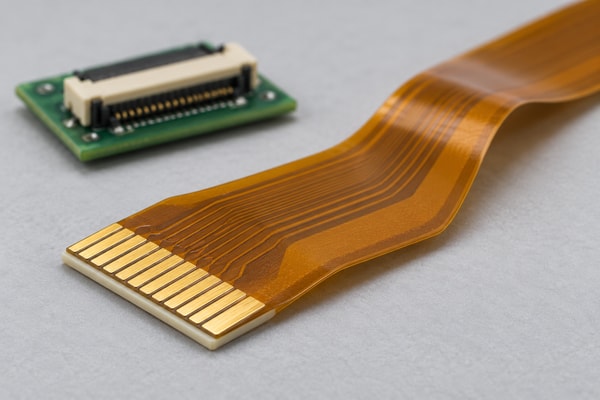
- Connector fit: Check contact pitch, exposed pad length, contact orientation, and finished insertion thickness against the connector drawing. Include both the stiffener and its bonding layer in the thickness calculation.
- Assembly access: Check coverlay clearances, component support, panel rails, fiducials, and test access. Resolve any conflict between the assembly panel and the final folded shape before production.
Low-noise ECG performance also depends on the circuit designer’s layout. Separating sensitive analog inputs from noisy signals and managing return paths are important layout considerations. Our manufacturing review helps preserve your approved layout; device-level noise and signal performance are verified during your product testing.
Materials and Stiffeners for Compact ECG Assemblies
Choose the flex stackup around the required movement, assembled thickness, and connector interface—not simply the thinnest available PI film. We manufacture with adhesive-based and adhesiveless polyimide constructions, with local reinforcement where contacts or components need support.
| Manufacturing Item | Standard Options | Selection Detail |
|---|---|---|
| Finished all-flex thickness | 0.06–0.60 mm | Depends on the complete stackup |
| Adhesive-based PI core | 0.5, 1, 2 mil | PI thickness only |
| Adhesiveless PI core | 0.5, 1, 2, 3 mil | PI thickness only |
| Copper foil | 0.33, 0.5, 1 oz | Selected adhesiveless materials also allow 2 oz |
| PI stiffener | 3, 5, 7, 9 mil | Bonding layer adds thickness |
| Surface finish | ENIG, gold plating, OSP, tin plating | Match soldering or contact requirements |
These are material and process options; the final combination follows the approved stackup. Core-film thickness is not the finished board thickness, and the thinnest construction is not available with every layer configuration.
- Connector tails: The reinforced end must meet the connector’s insertion specification while the adjoining flex remains free to bend.
- Populated flex: The support area should carry assembly loads without moving the bend into solder joints.
- Coverlay openings: Leave enough clearance for soldering while protecting adjacent conductors.
Skin-contact boundaries. For wearable products, distinguish the internal flex circuit from the skin-contact assembly. Enclosure sealing, electrodes, and medical adhesive selection belong in the product specification; standard FPC coverlay or mounting tape does not establish skin-contact suitability.
Quality Control and Traceability for ECG Board Orders
We check ECG boards against the released fabrication data and agreed acceptance criteria, combining circuit inspection, electrical testing, and dimensional checks. For US supplier quality teams, our medical FPC quality management approach also supports ISO 13485-related supplier evaluation and manufacturing documentation.
- Material verification: Match laminates, coverlay, and reinforcement materials to the approved construction.
- Circuit inspection: Use AOI to identify detectable conductor-pattern defects, with electrical testing for opens and shorts.
- Mechanical inspection: Check the outline, connector contact geometry, coverlay registration, and stiffener placement against the drawing.
- Order traceability: Agree the required material, lot, revision, and inspection records before production so the delivery package fits your receiving process.
Assembly testing. For assembled boards, define solder-joint inspection and any additional test coverage with the assembly order. An ECG waveform test needs an agreed procedure, input signal, fixture, firmware, and acceptance limits; a bare-board continuity test cannot establish the monitor’s measurement performance.
Our quality team can help your supplier qualification team identify the applicable certification and supporting records. ISO 13485 concerns the quality management system; it does not certify an individual PCB or finished ECG device.
From ECG Board Prototypes to Repeat Production
A successful prototype becomes a repeatable build when its approved materials, drawing revision, and acceptance criteria are carried into production together. We use the prototype stage to resolve manufacturing questions before a larger order depends on them.
Release the complete revision. After enclosure and electrical testing, update the Gerbers, stackup, stiffener drawing, BOM, and assembly notes as one controlled package. A revised connector or enclosure can affect the board even when the circuit itself has not changed.
Set change-approval rules. Specify which material substitutions, component alternatives, or process changes need your written approval. This gives procurement flexibility without silently changing a qualified construction.
Prepare the production build. Agree panelization, handling, inspection records, and delivery quantities for repeat orders. Where assembly is included, retain the approved placement data and test instructions with the board revision.
Transferring an existing design. If you are replacing an existing supplier, include the previous approved stackup, relevant inspection criteria, and any known fit or yield problems. That gives our engineers a useful starting point and helps your team compare the first build against a defined baseline.
ECG PCB Cost and Lead Times for US Buyers
Your ECG PCB quotation should distinguish board fabrication, assembly, tooling, and delivery costs, with a factory completion date separate from arrival in the United States. We price the released construction and requested quantities so purchasing can compare equivalent builds.
Compare total build cost. The main cost decisions are structural. Extra rigid-flex lamination, specialized materials, tight tolerances, and complicated outlines can increase fabrication effort. A simpler board may cost less, but extra connectors and assembly labor can change the overall comparison. Where practical, request pricing for prototype, pilot, and expected repeat-order quantities together.
We have no fixed minimum order quantity for custom FPC orders. Small builds still carry setup costs, and special materials may have purchasing minimums. Identifying those costs early helps development teams order what they need without mistaking prototype unit pricing for production pricing.
Plan manufacturing and US delivery separately. Lead time depends on material availability, engineering release, fabrication complexity, and inspection. For PCBA, component availability and test preparation also affect the schedule. Give us your required US arrival date at the quotation stage; our sales, engineering, production, and quality teams can then coordinate the build and shipping plan around that deadline.
Identify urgent-order options. For an urgent order, highlight any fixed materials, approved alternatives, and whether a partial shipment would help. This lets us investigate practical scheduling options without making unapproved changes to your design.
Why Choose BestFPC for ECG PCB Manufacturing?
BestFPC brings flex manufacturing experience, medical-sector quality discipline, and coordinated engineering support to ECG projects. For your team, that means a manufacturing partner who can discuss the board’s physical constraints, resolve build questions, and stay involved as the design matures.
Engineering Support for the Actual ECG Assembly
Our DFM discussions connect the circuit artwork to the installed board: the sensitive paths you need preserved, the flex section that must bend, and the connector that must fit. You receive manufacturing feedback tied to your drawings, giving your engineers a clear basis for approving changes.
Experience with Medical Customer Expectations
Long-term work with medical brands has made clear technical communication, manufacturing consistency, and delivery coordination part of our daily work. For an ECG program, we bring that experience to the supplier documentation and acceptance requirements your quality team needs to establish.
An Experienced Team That Stays with the Project
Our engineering, production, quality, and sales leaders each have more than 10 years of industry experience and more than 10 years with BestFPC. Their established working relationships help carry decisions from engineering into production, reducing repeated explanations when a prototype changes or an urgent build needs coordination.
Fabrication and Assembly Coordinated Together
Through our flex circuit assembly services, we coordinate board fabrication, component sourcing, SMT assembly, and agreed inspection or testing. Addressing board support and assembly needs together reduces the handoffs your team must manage between separate suppliers.
Whether you are developing a new ECG device or qualifying a replacement manufacturer, start with the current design package and the problems you need solved. We will help identify the manufacturing decisions needed for a useful quotation.
FAQs About ECG PCB Manufacturing
What files should I send for an ECG PCB quotation?
Send Gerber and drill files, the stackup or fabrication drawing, quantities, and your target delivery date. Include stiffener and mechanical drawings for flex constructions. For assembly, add the BOM, component placement file, and assembly instructions; identify any required testing or supplier documentation.
Can you quote from an ECG schematic alone?
A schematic is useful background, but it does not define the board dimensions, routing, layer construction, or mechanical interfaces needed for a firm fabrication quotation. Send the layout and manufacturing drawings when available, or describe the missing information so we can identify the next engineering inputs.
Can I supply components for assembly?
Yes. We offer consigned, turnkey, and partial-turnkey assembly arrangements. Identify which components you will supply and which we should source, including approved manufacturer part numbers, before pricing and scheduling the build.
Should every ECG interconnect have controlled impedance?
No. Apply controlled impedance to nets that require it under the circuit and interface specifications. Sensitive ECG analog inputs still need careful routing and leakage control, but a controlled-impedance callout alone does not establish low-noise performance.
Can the same flex construction be used for a fixed fold and repeated movement?
Do not assume so. A board folded during installation and a board that moves repeatedly face different mechanical demands. Specify the bend location, radius, movement, and expected cycles so the construction and qualification plan address the actual use.
With nearly 20 years of manufacturing experience and ISO 9001, ISO 13485, IATF 16949, and AS9100D certifications across the applicable management systems, BestFPC gives your team a strong basis for supplier qualification and consistent production. Free DFM, no fixed MOQ for custom FPC orders, and one-stop fabrication and assembly help you resolve build questions and move from samples to repeat orders with fewer handoffs. Send your ECG board files, quantities, and delivery priorities to sales@bestfpc.com for an engineering review and quotation.


.png)
.png)
.png)
.png)

.png)