


 2026-10-16
 BEST
BESTA catheter flex circuit must fit a narrow space while carrying the electrical connections needed at the distal end. Choosing one means balancing circuit width, channel count, length and movement—not simply selecting the smallest available trace width.
Start with the available space and the catheter’s intended motion. Then choose a circuit structure that supports the electrical requirements and can be manufactured consistently.
Planning a long, narrow interconnect? Send your preliminary outline, channel count and connection requirements to sales@bestfpc.com to discuss FPC manufacturing options.
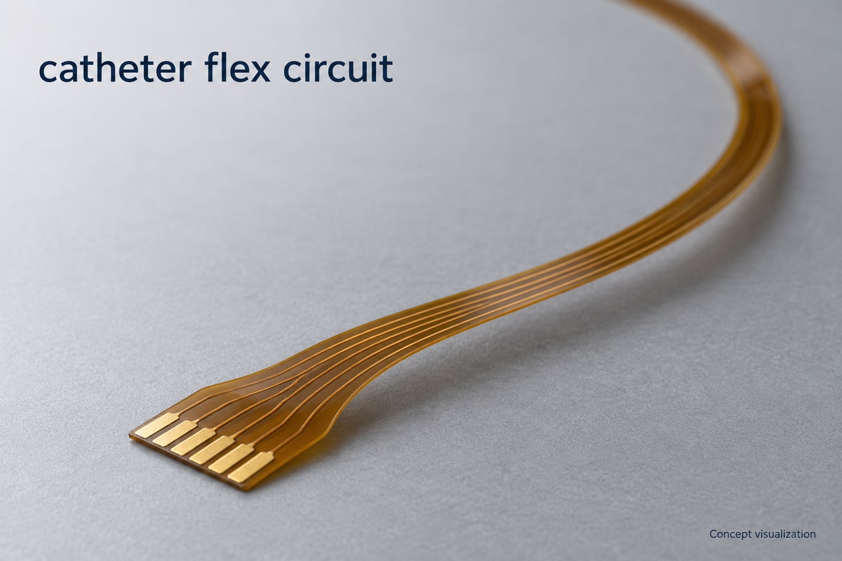
What Does a Catheter Flex Circuit Do?
A catheter flex circuit provides patterned conductive paths between electrical features within a catheter assembly. It can connect distal electrodes, sensors or other electronic components to proximal connections, depending on the device design.
Within the broader category of medical flexible circuits, catheter designs place particular emphasis on length, limited cross-sectional space and movement. Different regions have different jobs:
- Shaft: Carries conductors along the catheter while sharing space with other internal structures.
- Distal region: Routes connections to the functional elements near the tip.
- Proximal end: Provides the transition to a connector, cable or other electrical interface.
The FPC is one part of this assembly. Its outline and connection pattern must work with the catheter’s mechanical structure.
When Can Medical Flex Circuit Cables Replace Wires in a Catheter?
Medical flex circuit cables are worth considering when a defined conductor pattern can simplify routing and termination inside the available space. They are most useful when the benefits of an organized circuit outweigh the constraints of a flat substrate.
Evaluate three practical differences:
- Routing space: A flex circuit keeps conductors in a defined arrangement. Compare its complete insulated cross-section with the wire bundle, including the space needed for bending and assembly.
- Termination layout: Patterned pads can bring multiple connections to a defined interface. The benefit depends on how electrodes, sensors and proximal connections actually attach.
- Movement: A flat circuit has preferred bending directions. A wire-based solution may remain appropriate where the required movement or routing is poorly suited to the proposed flex geometry.
Compare both options inside the intended catheter structure, including their end connections and strain relief.
Which Catheter Flex Circuit Types Suit the Shaft and Distal Tip?
Choose the simplest layer structure that supports routing, electrical performance and assembly. The shaft and distal tip may need different outlines, pad arrangements or local support without requiring different layer counts.
| Structure | Potential benefit | Main trade-off |
|---|---|---|
| Single-layer flex | Simple routing structure | Limited routing freedom |
| Double-layer flex | Additional routing paths | Added thickness and interconnections |
| Multilayer flex | Greater routing capacity | More stackup complexity |
| Local stiffening | Supported termination areas | Less flexibility locally |
Local stiffening is a design feature, not a separate conductor-layer count. Use it where support is needed, while keeping its transition away from areas intended to flex sharply.
At the distal end, leave room for functional components and their connections. Along the shaft, assess the space occupied by the complete circuit stackup, including coverlay and any additional insulation used in the assembly.
How Do Medical Fine Line Flex Circuits Fit More Channels into a Catheter?
Medical fine line flex circuits can place more conductive paths within a limited width by reducing trace width and spacing. The useful density also depends on electrical requirements and whether those features can be reproduced over the full circuit length.
Four choices need to work together:
- Trace width: Narrower conductors save space but increase resistance when length and copper thickness remain unchanged. Evaluate signal and power paths separately.
- Trace spacing: Smaller gaps increase routing density. Select them with the operating voltage, insulation structure and manufacturing process in mind.
- Layer count: Additional layers create routing options but also add thickness and change mechanical behavior.
- Circuit length: A fine pattern must remain accurately formed and aligned across the complete long, narrow part.
For example, adding channels may require a wider circuit, finer features or another layer. Compare these options against the catheter’s available space and movement before committing to a stackup.
A supplier’s minimum line width and maximum circuit length should not be treated as a guaranteed combination. Review the proposed dimensions, copper thickness and layer structure together.
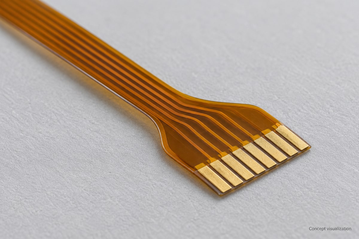
How Do Bending and Twisting Affect a Catheter Flex Circuit?
Bending and twisting place different demands on a flex circuit. The layout should reflect how the circuit moves inside the assembly, including where movement is concentrated.
- Installation bends: A bend formed during assembly needs adequate space and a controlled shape. Avoid forcing a sharp crease to make the circuit fit.
- Repeated bending: A region that moves repeatedly needs a construction and routing pattern suited to that motion. Keep abrupt stiffness changes and vulnerable connection features out of the moving region where possible. For repeated bending, compare RA vs ED copper alongside the foil grade, finished copper thickness and complete stackup.
- Twisting: Shaft rotation can apply torsional loading that a simple bend check does not represent. Assess it in the assembled geometry.
- Transitions: Stiffener edges, component areas and terminations can concentrate strain. Provide a gradual mechanical transition where the design allows it.
A flexible circuit is not automatically stretchable. Designs that require extension need a specifically engineered structure.
Mechanical evaluation should use the intended catheter assembly and motion. A flat-board inspection alone cannot demonstrate performance under repeated movement.
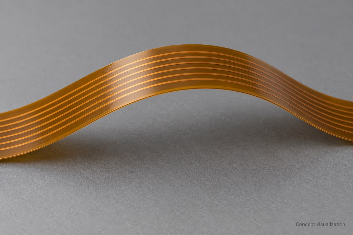
What Makes Long, Narrow Catheter Flex Circuits Difficult to Manufacture?
Long, narrow circuits combine delicate geometry with features that must stay aligned across a large length. Successful catheter flex PCB manufacturing therefore depends on handling, registration and inspection as well as nominal line width.
The main manufacturing challenges are:
- Layer registration: Conductors, openings and interconnections must align throughout the circuit. A demanding stackup can become harder to control as geometry and feature density increase.
- Handling and profiling: Thin, narrow parts can be damaged during processing, separation or packing. Manufacturing support and the release method need attention early in the design.
- Connection areas: Pad geometry, coverlay openings and local support must suit the planned attachment process.
- Inspection access: Electrical continuity and isolation checks should be planned alongside visual and dimensional inspection. Test access becomes more important when the final geometry is difficult to handle.
Discuss subsequent assembly temperatures and chemical exposure when selecting the material system. The substrate, adhesive, coverlay and surface finish need to be considered together.
Once the FPC is integrated, the device team still needs to evaluate the electrical and mechanical behavior of the complete assembly under its intended conditions.
Why Choose BestFPC for Your Catheter Flex Circuit Project?
BestFPC offers single-sided, double-sided and multilayer FPC manufacturing. This range provides a starting point for discussing the circuit structure needed for a catheter interconnect.
For your project, the manufacturing discussion can focus on three concrete decisions:
- An appropriate structure: Compare layer options against the required connections, available width and thickness.
- A manufacturable combination: Review length, copper thickness, trace geometry and openings as one design.
- Usable connection areas: Define pad locations, surface finish and local support around the intended assembly interfaces.
Bring the circuit drawing together with the space and movement requirements. This helps frame the discussion around the actual interconnect. The supply scope and achievable dimensions should be agreed for the specific design.
FAQs about catheter flex circuit
Can every catheter wire bundle be replaced with a flex circuit?
No. The best choice depends on routing space, electrical requirements, termination methods and movement. Some designs may benefit from wires or a combination of interconnects.
Are medical flex circuits always stretchable?
No. Flexibility allows bending, while stretchability involves extension. A catheter that requires the circuit to elongate needs a structure designed and evaluated for that movement.
Is polyimide alone enough to establish suitability for a catheter?
No. The complete material system and its role in the device matter. Patient-contact conditions, assembly processes and any intended sterilization exposure need to be evaluated for the actual construction.
Can I specify one minimum bend radius for every design?
No. The appropriate bend geometry depends on the stackup, thickness, conductor arrangement and whether the bend is static or repeated. Define the motion and assembly conditions before selecting a bend requirement.
Does ordering an FPC include a complete catheter?
An FPC order covers the agreed circuit supply scope. Catheter construction, integration and device-level validation are separate activities unless explicitly included in the supplier agreement.
Ready to develop your catheter flex circuit? Email your drawing, target dimensions and connection details to sales@bestfpc.com to discuss a manufacturing approach suited to your design.


.png)
.png)
.png)
.png)

.png)