


 2025-09-02
 BEST
BEST
You get the most flexibility in dfm flex pcb workflows by picking Valor NPI. This tool is special because it changes to fit your printed circuit board design needs. It also helps you make pcb manufacturing cheaper. Flexibility, efficiency, and reliability are important in design for manufacturability. You may have problems like not enough trace width, bad via strategy, and grounding that is not steady. Other problems are copper that is not spread out well, stack up that is not balanced, and fast heating during assembly. Using dfm helps you fix these problems and reach manufacturability standards.
Key Takeaways
- Valor NPI gives the most flexibility for DFM flex PCB design. It can change to fit different project needs.
- Pick a DFM tool that works with many materials like polyimide and copper foil. This gives you more choices for your design.
- Use strong design rule checks to find mistakes early. This helps save time and lowers costs when making PCBs.
- Find tools with 3D views and real-time feedback. These features help make designs more accurate and easier to finish.
- Talk to manufacturers early to avoid many design changes. This helps make sure your PCB meets production rules.
Flexibility in DFM Flex PCB Tools
What Flexibility Means
When you want flexibility in DFM flex PCB tools, you need more than checking your design. You want a tool that can change for your project. Flexibility means you can change settings and add your own rules. You can make the tool work with your way of designing. You might use different flexible pcbs, so your tool should work with many styles. Some tools let you use new materials or special stackups. Some tools help you use your favorite CAD software. This flexibility saves time and helps you make fewer mistakes.
Tip: Flexible tools help you find problems early. This saves you time and money when making your pcb.
Key Criteria
You should look for some features when picking a DFM tool for flexible pcbs. The tool should work with many materials and ways to make pcbs. For example, lots of flexible pcbs use polyimide because it bends and handles heat well. Your tool should let you set up stackups with polyimide, copper foil, adhesives, and coverlay. Each material needs something different when you design.
Here is a table that shows how materials change your design and how you make pcbs:
| Material Type | Key Properties | Impact on Manufacturing Processes |
|---|---|---|
| Polyimide | Very flexible, handles heat, strong | Good for tight bends, works for moving or still uses |
| Copper Foil | RA copper bends better than ED copper | Can bend tightly, even as small as 0.5 mm if thin |
| Adhesives | Builds without adhesive bend better | Makes pcbs thinner, good for tight bends |
| Coverlay | Polyimide coverlay protects and stays flexible | Thickness changes how much you can bend |
You also want a tool that works with your design process. It should work with your software and let you change checks for what you need. This helps you design flexible pcbs that match your ideas and what you need for manufacturing.
DFM Flex PCB Tool Comparison
Tool 1 Overview
You want a tool that helps you design printed circuit boards for many uses. Tool 1 stands out in the dfm flex pcb world because it supports many materials and design needs. You can use polyimide, which gives your printed circuit boards both flexibility and strength. This tool lets you set up your stackup with copper foil, adhesives, and coverlay. You can change the settings to match your project.
- Tool 1 helps you work with polyimide for flexible printed circuit boards.
- You can design for high accuracy and reliability.
- The tool lets you set the bend radius and choose the right components.
- You can make your printed circuit boards last longer and work better.
Tool 1 gives you strong thermal stability and can handle high heat. You get good results when your printed circuit boards need to bend or move. The main weakness is that you must watch your line width. If you do not keep the right trace width, your signals may not work well. You need to balance how your printed circuit boards bend with how they carry signals. Tool 1 helps you do this, but you must check your design often.
Tool 2 Overview
Tool 2 gives you many features for dfm flex pcb projects. You can use it to design printed circuit boards with special shapes and layers. The tool works well for many projects, but you will see some limits.
- You pay more for flexible printed circuit boards than for rigid ones.
- You cannot use heavy or large parts on the flexible areas. You need stiffeners for those parts.
- You must follow strict rules for trace width and spacing.
- If you need to fix your printed circuit boards, it is harder than with rigid boards.
Tool 2 helps you make complex printed circuit boards, but you must plan your design. You need to think about cost, part size, and repair. The tool gives you options, but you must follow the rules for flexible printed circuit boards.
Tool 3 Overview
Tool 3 gives you a different kind of flexibility for dfm flex pcb work. Many users like how you can change the tool to fit your needs. You can set up your printed circuit boards in many ways.
- You can use logic branching to make your design process easier.
- The tool lets you create paths that change based on your choices.
- You get strong options for data analysis and design feedback.
You will find that Tool 3 works well if you want to try new ideas or need special checks for your printed circuit boards. The tool helps you see problems early and gives you feedback as you work. Many users say it is easy to use and helps them finish their dfm flex pcb projects faster.
Note: Each tool gives you different ways to design flexible printed circuit boards. You should pick the one that matches your project and your way of working.
Key Features
Design Rule Checks
Strong design rule checks help you find mistakes early. These checks look for problems with trace width and spacing. They also check bend areas on your flex PCB. Good DFM tools let you set your own rules. You can change these rules for different materials or stackups. This helps you make better designs and avoid expensive errors. Using design rule checks makes sure your PCB works for you and the factory.
Material and Stackup Support
Your DFM tool should work with many materials and stackup choices. Flexible PCBs use polyimide, copper foil, adhesives, and coverlay. Each material changes how you design and build your board. You need to keep copper even on each layer to stop stress inside the board. A balanced stackup helps keep your board from bending during lamination and soldering. These features help you follow assembly rules and make your design better.
- Even copper on each layer stops stress inside the board.
- Balanced stackup keeps your board from bending during lamination and soldering.
- The material you pick changes how your board handles heat and bending.
3D Visualization & Real-Time Feedback
3D visualization tools let you see your flex PCB before you build it. You can check if parts fit and if the board bends the right way. Real-time feedback shows you problems as you design, so you can fix them fast. This makes your work more accurate and saves time.
| Evidence Description | Impact on Accuracy |
|---|---|
| 3D modeling and teamwork tools let you see harness paths and check fit before building. | Stops design mistakes before manufacturing. |
| Built-in design tools show real-time changes and traceability. | Cuts down on expensive mistakes and makes designs better. |
| Shared 3D space for assembly checks for fit and interference. | Makes designs more accurate by letting you check space. |
User Interface
A clear user interface helps you work faster. You want menus and tools that are easy to find. Good DFM tools let you drag and drop parts, zoom in on details, and switch views quickly. When you can see your design clearly, you make fewer mistakes. A simple interface also helps new users learn the tool faster.
Workflow Integration
Workflow integration lets you connect your DFM tool with other software and team members. You can share your design with engineers and get feedback early. This helps you catch errors, like wrong trace width, before you start building. Consistent DFM rules across your team reduce design changes and speed up your project. You can also check if parts are available, so you do not face delays from missing components.
- Early teamwork helps you find errors before fabrication.
- Consistent rules cut down on design changes.
- Checking parts early avoids delays from obsolete components.
Flexible PCBs: User Experience
Adapting to Design Environments
You work with many design environments when you create flexible pcbs. Some tools let you switch between different CAD programs. You can move your design from one software to another without losing important details. This helps you save time and avoid mistakes. You see how your flexible pcb will look in real life before you build it. Many tools show you a preview of your board and let you check if parts fit. You can spot problems early and fix them fast.
Tip: Try using a tool that works with your favorite design software. You will find it easier to share your work with your team.
You also need to think about how your design fits with manufacturing. Some tools help you match your design to the factory’s process. You can set rules for trace width, spacing, and bend areas. This makes your flexible pcb ready for production.
Customization Options
You want to make your flexible pcb fit your project. Good DFM tools let you change many settings. You can set your own design rules and stackup options. You choose the materials, like polyimide or copper foil, and adjust the thickness. You can add special layers or change the shape of your board.
Here are some ways you can customize your flexible pcb:
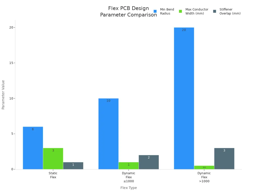
- Set custom bend radius for different parts of your board.
- Pick materials that match your needs for heat and movement.
- Change the size and shape to fit your device.
- Add stiffeners or extra layers for support.
| Customization Option | Benefit |
|---|---|
| Bend radius | Stops cracks and breaks |
| Material choice | Handles heat and bending |
| Shape changes | Fits tight spaces |
| Extra layers | Adds strength |
You get more control over your design. You can make your flexible pcb work better and last longer. Customization helps you solve problems and meet your project goals.
Value and Support
Pricing
You want to spend less money when making PCBs. You also want your DFM flex PCB tool to give you good value. The price changes for different reasons. How hard your design is, how many steps you need, and what your project needs all matter. Simple flex PCBs usually cost less at the start. These are good for easy or normal projects. Rigid-flex PCBs cost more money. They last longer and work better in tough places. You should pick the right type for your project.
Here is a table that shows what makes PCB costs go up or down:
| Factor | Impact on Cost-Effectiveness |
|---|---|
| Design Complexity | Harder designs cost a lot more |
| Manufacturing Steps | More steps make the PCB cost more |
| Application Needs | Special needs make the total price go up |
- Simple flex PCBs cost less for easy jobs.
- Rigid-flex PCBs cost more but last longer.
- If your design needs special things, it can cost more.
Tip: Plan your design early. This helps you save money later.
Support & Community
You need good help and a friendly community when using DFM flex PCB tools. Good help lets you fix problems quickly. Many top tools give you lots of ways to get help. You can watch webinars, try free trials, download products, and use online PCB viewers. Learning hubs and support centers answer common questions. Guides and training teach you new things. Forums let you talk to other users and get advice.
Here is a table with some support and community resources you can use:
| Resource Type | Description/Link |
|---|---|
| Safety & Reliability | Webinar on Strategies, Standards & Tools |
| Free Trials | Access Free Trials |
| Downloads | Download Products |
| Online PCB Viewer | View PCB Online |
| Learning Hub | Explore Learning Hub |
| Support Center | Visit Support Center |
| Documentation | Access Documentation |
| Webinars | Join Webinars |
| Altium Community | Community Forum |
| Bug Crunch | Report Bugs |
| Ideas | Submit Ideas |
| Professional Training | Training Programs |
| Education | Education Programs |
You can use these resources to learn new things, fix problems, and meet other people. This help lets you finish your projects faster and make fewer mistakes.
DFM Flex PCB Tools: Feature Table
When you pick a DFM Flex PCB tool, you want to know how each one compares. A feature table lets you see the main features next to each other. This helps you find the tool that fits your project best. The table shows things like flexibility, design rule checks, material support, 3D views, user interface, workflow integration, price, and support.
Tip: Look at this table to see which tool matches what you need. If you work on lots of projects, choose a tool with good customization and easy integration.
| Feature | Valor NPI | Tool 2 | Tool 3 |
|---|---|---|---|
| Flexibility | ⭐⭐⭐⭐⭐ | ⭐⭐⭐ | ⭐⭐⭐⭐ |
| Design Rule Checks | Advanced, Custom | Standard | Customizable |
| Material Support | Wide (Polyimide, etc.) | Good (Common materials) | Wide (User-defined) |
| Stackup Options | Full, Editable | Limited | Flexible |
| 3D Visualization | Yes, Real-Time | Basic | Yes, Interactive |
| User Interface | Intuitive, Modern | Simple | Visual, Easy-to-learn |
| Workflow Integration | Strong (CAD, ERP) | Moderate | API, Data Export |
| Pricing | Premium | Mid-range | Flexible plans |
| Support & Community | Large, Active | Good | Growing |
- Valor NPI gives you the most flexibility and strong design checks. It also has great material support and works well with other tools.
- Tool 2 is good for normal designs. It has basic features and supports common materials.
- Tool 3 lets you change many settings. You get feedback as you work and can pick a plan that fits your budget.
Note: If you need lots of features for hard flex PCBs, Valor NPI is the best. For easy jobs, Tool 2 might be all you need. Tool 3 is good if you want to try new things or need special checks.
You can use this table to help you decide. Pick the tool that fits your way of designing, your money, and your project. If you want more info, visit each tool’s website for demos and reviews.
Valor NPI is the most flexible tool for DFM flex PCB work. It gives you strong design rule checks. You can use many materials with it. The workflow is easy to use. Professionals need advanced features and good support. Hobbyists and entrepreneurs may want simple tools that cost less. Always pick a tool that fits your project. Place your components in the right spots. Talk to your manufacturer early to avoid mistakes and save money.
| Action | Benefit |
|---|---|
| Early manufacturer engagement | Reduces DFM violations and changes |
| Dedicated DFM reviews | Catches errors before release |
Tip: Think about how flexible the substrate is. Check thermal stability and electrical properties when you pick your DFM tool.
.png)
.png)
.png)
.png)

.png)

