


 2025-09-04
 BEST
BEST
When you design or select a flex circuit, understanding fpc cte is essential. The coefficient of thermal expansion (cte) measures how much a flex material expands as temperature rises. Imagine a flex board in a device that heats up and cools down repeatedly. If your flex material expands more than the attached silicon chip, the flex can crack or delaminate. Polyimide flex, with low cte, resists temperature swings and keeps your circuit reliable. Polyester flex, with higher cte, works best in low temperature flex applications. Your flex choice directly affects durability, stability, and thermal performance.
Key Takeaways
- Understanding CTE is crucial for selecting flex materials. It helps prevent issues like cracking and delamination in circuits.
- Matching CTE values between flex layers and components minimizes thermal stress. This step enhances reliability and performance.
- Use materials with low CTE for high-temperature applications. This choice improves stability and reduces the risk of failures.
- Evaluate CTE compatibility early in the design process. This approach helps avoid costly mistakes and ensures long-lasting circuits.
- Consider industry standards and testing methods to verify material choices. Following best practices leads to better flex circuit designs.
FPC CTE Basics

What Is FPC CTE
You encounter the term coefficient of thermal expansion (CTE) often when working with flex circuits. CTE describes how much a flex material expands as temperature changes. Manufacturers measure CTE in parts per million per degree Celsius (ppm/°C). This value tells you how much a material will stretch or shrink for every degree of temperature shift. For flex applications, controlling expansion is critical because different materials respond to temperature in unique ways.
- CTE values indicate how much a material's volume increases with temperature.
- CTE is measured in ppm.
- Typical CTE range for woven glass around PCB material is 10 to 20 ppm across the X and Y axes.
- For copper, the CTE is approximately 17 ppm/°C.
- For FR4, the CTE is typically 11 ppm along the board surface and 15 ppm perpendicular to it.
- Aluminum nitride has a low CTE value ranging from 4.3 to 5.8 ppm/°C.
Each flex material has its own CTE. Polyimide, for example, expands less than polyester or some other substrates. When you select a flex material, you must consider how its CTE matches with other components, such as copper traces or silicon chips. If the CTEs differ too much, the flex circuit can experience stress, leading to warping or cracking during temperature fluctuations.
Tip: Matching CTE values between flex layers and attached components helps minimize thermal stress and improves reliability.
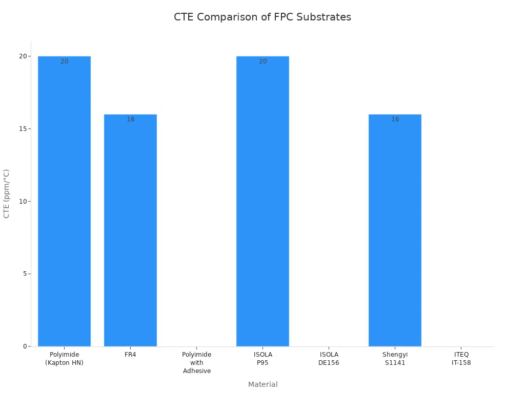
Here’s a comparison of CTE values for common flex substrates:
| Material | CTE (ppm/°C) |
|---|---|
| Polyimide (DuPont Kapton HN) | 20 |
| FR4 | 14-18 |
| Polyimide with Adhesive | 25 |
| ISOLA P95 | 13-14 |
| ISOLA DE156 | 45 |
| Shengyi S1141 | 65 |
| ITEQ IT-158 | 60 |
How CTE Is Measured
You need accurate CTE data to design reliable flex circuits. Several methods exist for measuring CTE in flex materials:
| Method Description | Details |
|---|---|
| ASTM E228 Modification | Modified for flexible materials, measures both long and short specimens to reduce error. |
| Real-time Strain Measurement | Uses thermal cycling instrumentation to monitor CTE changes over time and temperature. |
| Interferometric Techniques | Employs laser diffraction for precise measurements at various temperatures. |
| Strain Gages | Measures localized strain on flex boards, often combined with bulk measurements. |
You should always check the measurement method used by your flex supplier. Reliable CTE data ensures your flex circuit will withstand repeated temperature cycles without failure. Selecting materials with matching CTE values is crucial to minimize thermal expansion issues. Differences in CTE between flex laminate and copper can lead to excess stress, which may cause circuit failures. Flexible printed circuits help mitigate these mismatches, enhancing reliability under temperature fluctuations.
Why FPC CTE Matters
Impact on Performance
You need to understand how fpc cte affects flex pcb performance. When you select materials for flex, you must consider how each layer expands with temperature changes. If you ignore cte mismatch, you risk mechanical stress that can damage your printed circuit board. Flex circuits with high cte values often experience warping, delamination, or cracking. These problems occur because different materials expand at different rates during thermal cycling.
- A mismatch in cte between flex and components causes mechanical stress and cracking.
- Thermal stress failures often result from cte mismatch.
- Post-test inspections should focus on internal structures, especially via wall integrity.
- Microvia reliability is critical in high-density interconnect boards due to thermal stress.
Flex pcb design for high-temperature applications requires careful attention to fpc cte. Advanced materials with lower cte values provide better stability in extreme conditions. FR-4, with a cte of 14-17 ppm/°C, suits many designs, but you should choose materials with even lower cte for high-temperature flex pcbs. When you run thermal cycling tests, you expose flex circuits to repeated temperature extremes. Each cycle includes temperature dwell periods and rapid transitions. These tests reveal issues like cte mismatches, solder joint fatigue, and interfacial delamination.
Note: Matching fpc cte across all flex layers and components helps you avoid costly failures and ensures reliable flex pcb performance.
Reliability Issues
You face reliability challenges when you use flex circuits in high-temperature environments. The mismatch in fpc cte among different materials leads to mechanical stress. Materials expand and contract at different rates when exposed to temperature changes. This stress can cause warping, delamination, or cracking in flex circuits. You must select materials with compatible cte values to maintain high-temperature stability.
| Material Type | Effect at High Temperatures |
|---|---|
| PVC | Softens, decomposes, or melts, leading to insulation failure |
| Metal Contacts | Deform due to thermal expansion, impacting electrical contact quality |
| High-Temperature Materials | Maintain excellent electrical performance and physical stability under high temperatures (e.g., PTFE, silicone rubber) |
You see the importance of fpc cte in industries like aerospace, automotive, and consumer electronics. In aerospace and automotive, low cte materials are essential for circuit stability under temperature fluctuations. Consumer electronics focus on flexibility and transparency, but cte remains important for reliability in varying conditions.
| Industry | CTE Priority |
|---|---|
| Aerospace | Low cte materials are essential for circuit stability under temperature fluctuations. |
| Automotive | Low cte is crucial for maintaining stability in varying temperatures. |
| Consumer Electronics | Flexibility and transparency matter, but cte is still important for reliability. |
You must prioritize fpc cte when designing high-temperature flex pcbs. High-temperature environments impact the long-term reliability of flex circuits with varying cte values. If you use materials with high cte, you increase the risk of insulation failure, electrical contact issues, and physical instability. High-temperature flex pcbs require materials that maintain performance and resist expansion during temperature changes.
Tip: Always evaluate fpc cte for your flex pcb design, especially for high-temperature applications. This step helps you prevent failures and extend the life of your printed circuit board.
FPC CTE in Design

Material Selection
When you design a flex pcb, you must pay close attention to material selection. You want your flex circuit to withstand high-temperature environments and repeated flexing. You should always check the coefficient of thermal expansion for each material. If you choose materials with similar expansion rates, you reduce mechanical stress and improve durability.
You can use several strategies to minimize CTE-related problems in flex pcb design:
- Reinforce high-stress areas with polyimide stiffeners or thicker copper layers.
- Use flexible solder masks to prevent cracking during repeated bending.
- Select materials with compatible CTE values to reduce stress.
- Consider single-layer flex circuits to minimize stress on copper.
- Avoid bends at overlapping sections to enhance durability.
Material innovation continues to improve flex pcb design. Nano-ceramic-filled polyimide now reduces expansion to just 8ppm/°C, making it ideal for high-temperature applications. You can also take advantage of roll-to-roll production, which lowers costs for complex flex circuits.
| Evidence Type | Description |
|---|---|
| Material Innovation | Nano-ceramic-filled polyimide reduces CTE to 8ppm/°C. |
| Process Revolution | Roll-to-Roll (R2R) production cuts 8-layer FPC cost by 28%. |
Engineering Considerations
You need to understand how glass transition temperature (Tg) affects CTE values and circuit stability. Tg marks the point where a flex material shifts from rigid to rubbery. When you use high Tg materials, you get lower CTE values and better high-temperature stability. This choice helps your flex pcb design resist expansion and maintain performance in demanding environments.
| Type of PCB | CTE Value (ppm/°C) |
|---|---|
| High Tg PCB | 10-15 |
| Standard FR-4 | 16-18 |
You should always select materials with high Tg for high-temperature applications. This step ensures your flex circuit remains stable and reliable. If you ignore Tg, you risk expansion problems and reduced printed circuit board lifespan.
Tip: Always match CTE and Tg values to your application's temperature range. This approach gives you the best chance for long-term reliability in flex pcb design.
Practical Tips
Evaluating FPC CTE
You can improve flex reliability by evaluating the coefficient of thermal expansion during the design phase. Start by selecting materials with compatible CTE values. This step helps you minimize warpage and reduce stress during temperature cycling. Matching the CTE of each layer in your flex stack-up ensures your printed circuit board stays stable under high-temperature conditions.
You should also consider using specialized substrate materials, reinforcement fibers, or advanced resin systems. These options help maintain dimensional stability across a wide range of temperature changes. Manufacturers often follow best practices such as:
- Choosing rigid materials with lower CTE and high-Tg adhesives
- Using multi-stage lamination with controlled press cycles
- Designing smooth transitions with fillets and avoiding sharp corners
To verify your choices, you can rely on industry standards and testing methods. The table below highlights key IPC standards for assessing CTE in flex:
| IPC Standard | Scope | Use Cases |
|---|---|---|
| IPC-6013 | Qualification and performance specs | Prototype validation for thermal cycling and bending |
| IPC-2223 | Component mounting and interconnection systems | Hybrid systems, wearables, IoT devices |
| IPC-9204 | Flexibility and stretchability | Foldable smartphones, wearable health monitors |
| IPC-9257 | Electrical testing procedures | Electrical performance verification |
| IPC-TM-650 | Standardized test methods | Consistency and reliability in production |
| IPC-TM-650 2.6.21B | Service temperature of metal-clad flexible laminates | Material selection for heat-intensive, high-temperature applications |
You should also run thermal cycling, thermal shock, aging, and mechanical stress tests to confirm your flex can handle real-world conditions.
When CTE Is Critical
You must pay special attention to CTE in several scenarios. Dynamic flexing, such as in wearable electronics or automotive systems, puts repeated mechanical stress on your flex. High-temperature environments, like under-hood automotive or industrial controls, demand materials that resist expansion and maintain stability.
In these cases, you should use high glass transition temperature materials, such as polyimide films. These materials combine low CTE and high Tg, which helps prevent failures during flexing and temperature swings.
You see CTE become a key factor when:
- Your flex circuit will experience frequent bending or vibration
- The application involves rapid or extreme temperature changes
- You design for high-temperature applications or harsh environments
- Your flex pcb design includes multi-layer assemblies with different materials
Tip: Always evaluate CTE compatibility early in your design process. This approach helps you avoid costly failures and ensures your flex performs reliably in any environment.
You need to understand how the coefficient of thermal expansion shapes the reliability of flexible printed circuit boards. When you select flexible circuit materials for flex pcb design, you must consider high-temperature performance and temperature stability. Matching CTE values across flex layers prevents warping and cracking in flex applications.
| Material Type | CTE Value (ppm/°C) | Implications for Reliability |
|---|---|---|
| Rogers 4000 Series FR-4 | Higher than PTFE | Increased mechanical stress and potential delamination |
| High-frequency PTFE (Teflon) | 10 | Lower expansion, leading to mismatch issues |
Industry standards guide you to choose materials and stack-ups that resist temperature swings and high-temperature stress.
| IPC Standard | Description |
|---|---|
| IPC-2221A | General guidelines for designing printed circuit boards, emphasizing material selection and thermal compatibility. |
| IPC-2223 | Specific guidelines for flexible printed circuits, including layer stack-up and material properties to manage thermal expansion. |
- Focus on compatible flex materials for high-temperature environments.
- Monitor temperature effects on flex and printed circuit board reliability.
- Prioritize CTE in every flex project for long-term performance.
You improve durability and stability when you pay attention to CTE and temperature management in flex applications.
.png)
.png)
.png)
.png)

.png)

