


 2026-10-20

 BEST
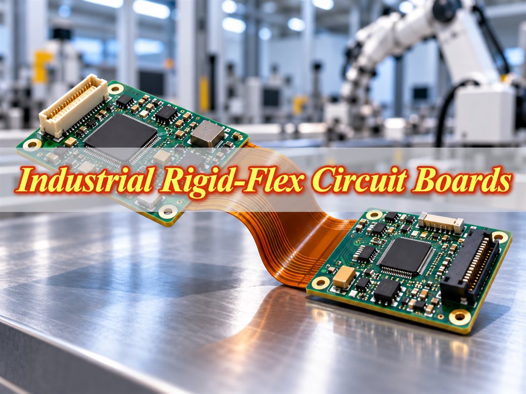
An industrial rigid-flex circuit board joins component-loaded rigid sections through integrated flexible connections. It can replace cable links inside robotic controllers, industrial sensors, and inspection equipment where space and connector access are limited.
BestFPC manufactures custom rigid-flex PCBs and provides assembly services, from initial samples to repeat production orders. Board geometry, materials, and bending requirements are reviewed against the customer's approved files before fabrication.
Where Are Industrial Rigid-Flex Circuit Boards Used?
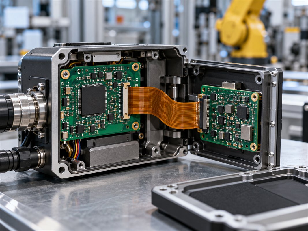
Industrial rigid-flex circuit boards are used where two or more circuit sections must fit at different positions inside the same enclosure. The rigid areas support components, while the flexible areas carry signals or power between them.
| Industrial Equipment | Typical Use | Reason for Rigid-Flex |
|---|---|---|
| Robotic Control Modules | Links compact control and sensor boards | Reduces internal cable and connector space |
| Machine-Vision Cameras | Connects image sensors to processing electronics | Fits circuits around lenses and mounting features |
| Industrial Sensor Heads | Connects a narrow sensing tip to a larger control section | Places electronics inside restricted housings |
| Encoders and Motion Controllers | Joins sensing and interface circuits at different angles | Simplifies fixed internal interconnections |
| Portable Industrial Instruments | Connects displays, controls, and main electronics | Allows folded board layouts |
A flex section that moves during operation needs a different construction from one folded only during installation. The bending cycle requirement must be specified before materials and stackup are finalized.
Why Choose Rigid-Flex PCBs for Industrial Equipment?
Rigid-flex PCBs reduce wiring complexity, save installation space, and simplify assembly in compact industrial equipment. By integrating rigid and flexible sections into one circuit, they eliminate the need for some separate cables and connectors.
- Space Savings: Flexible connections allow rigid circuit sections to fit at different angles inside compact enclosures without extra cable-routing space.
- Simplified Assembly: Integrated interconnections reduce cable installation, connector mating, and manual assembly steps.
- Fewer Connection Failures: Eliminating selected connectors reduces the risk of loose contacts, connector wear, and cable damage.
- Flexible Mechanical Layout: Rigid sections support electronic components, while flexible sections accommodate folded or angled installations.
- Potential Cost Savings: Although rigid-flex PCB fabrication is more complex, fewer connectors, cables, and assembly operations can reduce total product costs.
Rigid-flex PCBs are particularly suitable for compact industrial equipment with fixed internal connections. For products requiring frequent module replacement, separate rigid PCBs with detachable connectors may be more practical.
What Are the Design Parameters for Industrial Rigid-Flex PCBs?
A manufacturable industrial rigid-flex PCB needs a defined mechanical drawing and stackup, not just Gerber files. The bend conditions and rigid-to-flex transitions are as relevant as trace widths and hole sizes.
| Parameter | What to Specify | Practical Consideration |
|---|---|---|
| Rigid and Flexible Layers | Layer count in each rigid area and continuous flex section | Not every rigid copper layer needs to continue through the flex |
| Finished Thickness | Rigid-area thickness and tolerance; flex thickness | Affects enclosure fit, connector engagement, and stiffness |
| Bend Radius | Minimum installed radius in mm, bend angle and direction | Must be checked against the actual flex stackup |
| Bend Type | One-time installation or repeated movement; expected cycles | Dynamic flexing may require a different copper and layer construction |
| Flex Length and Shape | Length, width, fold position, and enclosure clearance | Prevents creasing or tension during installation |
| Rigid-to-Flex Transition | Transition location and nearby component, via, or mounting features | Concentrated strain can damage conductors at the boundary |
| Copper and Circuit Geometry | Copper weight, minimum trace width/spacing, current requirements | Balances routing density, heat, and flexibility |
| Holes and Vias | Finished hole size, via type and position | Plated features should be kept out of bend zones unless specifically qualified |
| Signal and Environment | Impedance targets, operating temperature, humidity, vibration | Determines stackup and acceptance requirements |
There is no single safe bend radius for every industrial rigid-flex circuit board. A thick multilayer flex section and a thin single-layer flex tail behave differently. Radius and cycle life must be assessed for the approved construction.
What Materials and Stackup Options Are Available for Industrial Rigid-Flex PCBs?
Polyimide forms the flexible sections; FR-4 commonly supports the rigid mounting areas. Copper type, bonding material, and protection are selected around the intended bend and assembly conditions.
| Material or Feature | Common Options | Selection Guidance |
|---|---|---|
| Flexible Base | Adhesive or adhesiveless polyimide (PI) | Adhesiveless PI can reduce thickness in bend areas |
| Rigid Laminate | Standard or high-Tg FR-4 | Match assembly temperature and service environment |
| Flex Copper | Rolled-annealed (RA) or electrodeposited (ED) | Evaluate thickness, grain structure, and required bend life together |
| Bonding | Compatible low-flow prepreg | Limits unwanted resin flow into exposed flex sections |
| Flex Protection | Polyimide coverlay | Protects traces without using rigid-area solder mask over active bends |
| Surface Finish | ENIG, ENEPIG, and other approved finishes | Choose for solder joints and contacts; keep unsuitable finishes away from bend zones |
| Specialized Features | EMI shielding, controlled impedance, blind/buried vias | Check their placement and compatibility with the layer construction |
A typical construction may use four copper layers in the rigid sections and two in the flexible connection. The actual stackup depends on electrical routing, bend space, and manufacturing approval; it should not be chosen from layer count alone.
How Are Industrial Rigid-Flex PCBs Manufactured and Assembled?
Fabrication combines flexible-circuit processing with rigid-board lamination; assembly adds components after the finished board passes inspection. The flexible sections need support during handling, solder printing, placement, and reflow.
Step 1: Fabricate the Flexible Circuits. Copper patterns are formed on the selected PI material. Coverlay protects the conductors, leaving the required connection pads exposed.
Step 2: Build the Rigid Sections. Approved rigid materials are laminated around the flexible construction. Drilling, plating, and circuit processing establish the specified interconnections.
Step 3: Finish and Inspect the Boards. The outline and exposed flexible regions are processed, followed by surface finishing, dimensional checks, and electrical continuity/isolation testing.
Step 4: Assemble the Components. SMT and, when required, through-hole components are mounted on supported areas. Carriers or fixtures hold irregular outlines and flex tails in position. AOI and any customer-specified functional testing follow the agreed assembly plan.
Assembly drawings should identify component-free flex areas and any required support points. These details affect fixture design and handling more than the number of components alone.
What Affects Industrial Rigid-Flex PCB Cost and Lead Time?
Layer construction, special processes, component availability, and order quantity have the greatest effect on the quotation. A comparable price requires the same fabrication revision, stackup, and assembly scope from each supplier.
| Factor | Cost Impact | Lead-Time Impact |
|---|---|---|
| Layer Count and Lamination | More materials, registration, and processing | Additional fabrication stages |
| Flex Geometry and Board Outline | More complex tooling and handling | Extra profiling and dimensional checks |
| Fine Traces, Microvias, or Impedance Control | Specialized processing and inspection | Engineering review and additional operations |
| Materials and Surface Finish | Different laminate and finish costs | Nonstock materials may require sourcing |
| Order Quantity and Panel Utilization | Setup cost spread over different quantities | Capacity and material allocation change by lot size |
| PCB Assembly and Testing | Component sourcing, fixtures, soldering, testing | BOM availability and test preparation affect the schedule |
Provide both prototype quantities and expected repeat-order volumes in the RFQ. The factory can then assess panel utilization, material procurement, and assembly needs against your actual purchasing plan.
Why Choose BestFPC for Industrial Rigid-Flex PCB Manufacturing?
BestFPC manufactures custom rigid-flex circuits in China and offers SMT assembly support. Its published manufacturing options include flexible PI cores, high-Tg FR-4, low-flow prepreg, RA/ED copper, and multilayer rigid-flex constructions.
- Custom Rigid-Flex Stackups: Rigid and flexible layer arrangements tailored to the supplied drawings, including bonded and air-gap flex constructions where applicable.
- DFM Review: Checks of bend positions, transition areas, via placement, material compatibility, and tolerances before fabrication. BestFPC supports manufacturing review rather than taking ownership of circuit design.
- Advanced Fabrication Options: Controlled impedance, EMI shielding, blind/buried vias, and surface finishes including ENIG and ENEPIG, subject to the approved stackup.
- Fabrication Plus Assembly: Bare-board manufacturing and SMT assembly can be coordinated under the same project, including agreed inspection and testing requirements.
- Prototype and Repeat Orders: Samples, small batches, and volume orders can be quoted against the approved revision. IPC-6013 Class 2/3 manufacturing options are listed in BestFPC's published capabilities; the required class must be agreed for each project.
- For an industrial rigid-flex circuit board with unusual folds, materials, or assembly requirements, send the mechanical drawing with the PCB files so feasibility and quotation can be checked together.

What Information Is Needed for an Industrial Rigid-Flex PCB Quote?
Send the circuit files, mechanical drawing, stackup, and requested quantity together. Omitting the bend details or flexible-area thickness can result in a quotation for the wrong construction.
- Fabrication Files: Gerber or ODB++, drill data, fabrication notes, and revision number.
- Mechanical Details: Rigid/flex outlines, thicknesses, bend radius and direction, hole positions, and dimensional tolerances.
- Materials and Electrical Requirements: Layer stackup, copper weights, surface finish, impedance targets, and environmental requirements.
- Assembly Files, If Required: BOM, pick-and-place data, assembly drawings, supplied/approved parts, and testing instructions.
- Purchase Details: Prototype quantity, expected production quantities, requested delivery date, and destination.
If a particular material, IPC acceptance class, or report is mandatory, include it in the RFQ rather than adding it after the quotation has been approved.
FAQs About Industrial Rigid-Flex Circuit Boards
Q1: Can a rigid-flex assembly be folded after soldering?
A1: Yes, if the bend is specified and the assembled components are outside the stressed area. Follow the approved folding direction and radius; do not force a crease.
Q2: Can a rigid-flex PCB be supplied in panels for automated assembly?
A2: Yes, where the outline and support features allow panelization. Agree on panel rails, fiducials, support points, and depaneling before fabrication.
Q3: Can customers supply their own components for SMT assembly?
A3: This can be arranged by agreement. Confirm the component list, packaging, quantities, and how shortages or damaged parts will be handled.
Q4: Can one purchase order contain different PCB revisions?
A4: Yes, if each revision is clearly identified with its own fabrication files and quantity. Do not combine revisions under an indistinguishable part number.
Q5: Can serial numbers or lot codes be added to the boards?
A5: Labeling or serialization can be specified. Provide the marking content, location, size, and required traceability format.
Q6: How should exposed flexible tails be protected during shipment?
A6: Packaging should keep them from being crushed, kinked, or bent below the approved radius. The packing method should match the outline and surface finish.
Q7: Can functional testing or firmware programming be included with assembly?
A7: It depends on the test fixture, firmware, access points, and agreed scope. Supply the test procedure and acceptance criteria before quotation.
Q8: Can an approved material be replaced if it becomes unavailable?
A8: Only with customer authorization where the material is controlled by the specification. A replacement may change flex thickness, bending performance, or assembly behavior and should be reviewed before use.
Conclusion
An industrial rigid-flex circuit board should be specified around the enclosure, bend conditions, and assembly requirements—not layer count alone. Clear fabrication data helps avoid mismatched materials, mechanical-fit problems, and unnecessary quotation revisions.
BestFPC provides custom rigid-flex PCB manufacturing and assembly for prototype, small-batch, and volume orders. Send your Gerber files, mechanical drawing, stackup, BOM (if needed), and quantities to sales@bestfpc.com for a project-specific quotation.


.png)
.png)
.png)
.png)

.png)