


 2026-11-19

 BEST
A high current flex PCB must carry substantial electrical current within limited space while controlling heat generation, voltage drop, and long-term reliability risks. Copper thickness, trace width, and stackup construction directly affect electrical performance and manufacturing feasibility. BestFPC provides custom high current flex PCB manufacturing, including heavy copper options, fast prototyping, and batch production according to customer-approved specifications.
Are you struggling with overheating traces, excessive voltage drop, or unreliable connections in your high-current flexible circuit? Simply increasing copper thickness may not solve these problems and can make fabrication and installation more difficult. BestFPC helps identify manufacturing constraints before production and manufactures flexible circuits using suitable materials, controlled fabrication processes, and confirmed mechanical specifications.
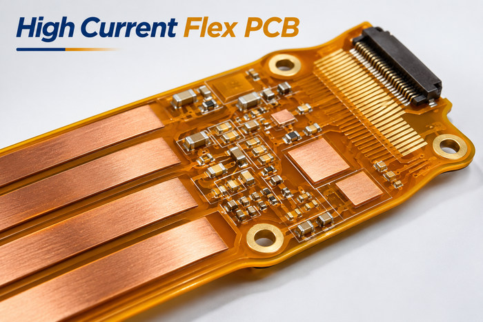
What Is a High Current Flex PCB and Where Is It Used?
A high current flex PCB is a flexible printed circuit designed to transfer electrical power while meeting specific current, temperature, and mechanical requirements. Compared with conventional signal FPCs, it generally requires a larger copper conductor cross-section and greater attention to power connections and operating conditions.
Typical applications include:
-
Battery and power systems: Electrical connections between battery management modules, power controllers, and internal power interfaces.
-
Industrial power equipment: Compact interconnections between power modules, control units, and electrical assemblies with limited installation space.
-
Automotive electronics: Power connections for auxiliary electrical systems, actuators, and selected automotive control modules.
-
Medical electronic equipment: Customized power interconnections for compact monitoring, diagnostic, and portable medical devices.
-
Robotics and automation: Power connections requiring specific installation geometries or controlled movement, provided the flexible construction meets the mechanical requirements.
A high current flex PCB can integrate multiple power paths into a thin, customized circuit, reducing the need for certain individual wires and connectors. However, applications involving continuous high current, frequent movement, or significant vibration require careful evaluation of both electrical and mechanical conditions.
How Much Current Can a High Current Flex PCB Carry?
The current-carrying capacity of a high current flex PCB depends on conductor cross-sectional area, allowable temperature rise, and operating conditions—not copper thickness alone. Two flexible circuits with identical copper thickness may have significantly different current ratings because of their conductor dimensions and thermal environments.
The main factors include:
-
Finished copper thickness: Thicker copper provides a larger conductor cross-section and generally reduces electrical resistance at the same trace width.
-
Trace width: Wider conductors reduce resistance per unit length but require additional routing space.
-
Conductor length: Longer current paths increase total resistance, voltage drop, and resistive power loss.
-
Allowable temperature rise: Applications with strict temperature limits generally require more conservative conductor sizing.
-
Operating environment: Enclosed housings, nearby heat sources, airflow, and surrounding materials affect heat dissipation.
-
Current profile: Continuous current, short-duration peaks, and periodic loads require different thermal evaluations.
For example, a 70 µm copper conductor has approximately half the theoretical resistance of a 35 µm conductor when both have the same width, length, and temperature. However, this does not mean its safe current capacity automatically doubles.
IPC-2152 provides guidance for evaluating conductor dimensions, current, and temperature rise. For high current flex PCB applications, the final conductor dimensions should also account for the actual stackup, installation environment, and maximum permitted operating temperature.
What Copper Thickness and Stackup Are Suitable for High Current Flex PCBs?
1 oz and 2 oz copper are common starting options for high current flex PCB designs, while 3 oz and 4 oz copper may be suitable for specialized heavy copper constructions. The appropriate choice depends on current requirements, available trace width, overall thickness, and installation geometry.
Common copper thickness options include:
-
1 oz (approximately 35 µm): Suitable when wider power traces can provide sufficient current-carrying capacity.
-
2 oz (approximately 70 µm): Provides a larger conductor cross-section within the same trace width, helping reduce electrical resistance.
-
3 oz (approximately 105 µm): An option for specialized high-current applications requiring greater attention to etching accuracy and conductor spacing.
-
4 oz (approximately 140 µm): Used in selected heavy copper flex PCB constructions, generally where mechanical bending requirements are less demanding.
These are nominal copper thickness values. Finished conductor thickness and manufacturing tolerances must be specified separately where required.
Stackup selection depends on the electrical connections and mechanical arrangement:
-
Single-layer FPC: Suitable for relatively simple power connections and single-sided conductor layouts.
-
Double-layer FPC: Provides additional routing options for power and signal circuits in more complex assemblies.
-
Multilayer FPC: Supports multiple power and signal layers but increases overall thickness and bending stiffness.
-
Adhesiveless polyimide construction: Can reduce adhesive-related thickness compared with certain adhesive-based laminates, making it suitable for applications with strict thickness requirements.
Thicker copper is not always the best solution. Where routing space permits, increasing trace width may be preferable to increasing copper thickness.
For circuits requiring installation bending, the specified bend radius, bending cycles, and overall construction must also be considered. Heavy copper generally increases stiffness and should not automatically be assigned the same bending limits as conventional thin-copper flexible circuits.
How Can High Current Flex PCBs Reduce Heat and Voltage Drop?
Reducing resistance throughout the complete current path is essential for limiting heat generation and voltage drop in a high current flex PCB. Connector interfaces, narrow conductor sections, and poorly arranged transitions can create additional losses even when the main power traces have sufficient copper.
Effective improvements include:
-
Shorten power paths: Reduce unnecessary routing length to lower total conductor resistance.
-
Eliminate narrow bottlenecks: Check trace-to-pad transitions, power branches, and connector areas for insufficient conductor width.
-
Reduce connection resistance: Select suitable contact areas, termination structures, and connection methods for the required current.
-
Use parallel current paths where appropriate: Multiple conductors can share current when their connections and current distribution are properly considered.
-
Improve thermal conditions: Account for enclosure design, nearby heat sources, airflow, and surrounding materials to minimize localized heat accumulation.
Connection areas deserve particular attention. A circuit with adequately sized power traces can still experience localized overheating if connector contact resistance is excessive.
When conductor resistance remains constant, doubling the current produces four times the resistive power loss. Therefore, a high current flex PCB should be evaluated against its actual continuous operating current and temperature limits rather than conductor dimensions alone.
What Are the Main Manufacturing Challenges of High Current Flex PCBs?
The main manufacturing challenges of high current flex PCBs involve heavy copper etching, coverlay insulation, interlayer connections, and dimensional accuracy around termination areas. If these requirements are not addressed before fabrication, the finished circuit may suffer from conductor deviations, insulation defects, or poor connector fit.
-
Heavy copper etching: Thicker copper makes lateral etching more significant. When wide power traces and fine signal traces share the same circuit, achievable trace width, spacing, and tolerances must be confirmed for the selected copper weight.
-
Coverlay bonding: Heavy copper creates larger height differences between conductors. Coverlay materials and adhesives must provide adequate coverage around copper edges to prevent insulation gaps or poor bonding.
-
Interlayer connections: Vias and plated through-holes in double-layer or multilayer FPCs must meet the specified electrical and mechanical requirements. Signal-via dimensions should not be assumed suitable for substantial continuous current.
-
Termination accuracy: Connector tails and solder terminals require controlled finished thickness, contact dimensions, and surface finishes to ensure proper assembly.
-
Localized mechanical stress: Reinforcement edges, abrupt copper transitions, and nearby bend areas require careful construction to reduce stress concentration.
For special heavy copper applications, manufacturing feasibility must be evaluated against the complete stackup. Fine-line and bending capabilities available for conventional thin-copper FPCs may not apply to thicker copper constructions.
What Custom High Current Flex PCB Manufacturing Services Does BestFPC Offer?
BestFPC manufactures custom high current flex PCBs according to customer-approved Gerber files, stackups, copper specifications, and mechanical drawings. Available options include conventional polyimide flexible circuits and selected specialized heavy copper constructions.
Our main manufacturing capabilities include:
| Manufacturing Item | BestFPC Capability |
|---|---|
| Standard pure-flex PCB layers | 1–4 layers |
| Standard finished FPC thickness | 0.06–0.60 mm |
| Adhesiveless PI core thickness | 0.5, 1, 2, 3 mil |
| Standard adhesiveless PI copper options | 0.33, 0.5, 1, 2 oz |
| Special heavy copper options | Up to 4 oz, subject to construction review |
| Reference external trace width/spacing at 70 µm finished copper | 8/8 mil before manufacturing compensation |
| PI stiffener thickness | 3, 5, 7, 9 mil |
| Surface finishes | ENIG, electroplated gold, OSP, immersion tin |
Special heavy copper projects require confirmation of conductor dimensions, material availability, layer construction, and mechanical requirements.
BestFPC provides the following custom manufacturing services:
-
Custom high current flex PCB fabrication: Manufacture flexible circuits to approved conductor patterns, board outlines, and dimensional requirements.
-
Heavy copper FPC manufacturing: Evaluate and fabricate suitable thick-copper constructions for specialized power interconnections.
-
Custom PI and coverlay processing: Produce specified insulation structures, coverlay openings, and protective layers.
-
Custom outlines and local reinforcement: Manufacture connector tails, irregular board shapes, and reinforced regions according to mechanical drawings.
-
Prototype and batch manufacturing: Support custom prototypes and subsequent production orders using approved fabrication documentation.
-
Free DFM check: Evaluate copper weight, trace spacing, material combinations, and structural manufacturing constraints before production.
For special high-current constructions, customers are encouraged to provide their operating-current requirements and mechanical drawings together with the fabrication files.
Engineering Example: How Can a 10 A High Current Flex PCB Reduce Voltage Drop and Power Loss?
Consider a compact industrial power module that requires a flexible circuit to connect two internal power interfaces. Installation space is limited, and the FPC is bent once during assembly before remaining fixed in position.
The objective is to compare the electrical performance of 1 oz and 2 oz copper without increasing the available conductor width.
Project requirements
-
Operating current: 10 A continuous
-
Conductor length: 100 mm
-
Conductor width: 5 mm
-
Copper options: 1 oz and 2 oz
-
Base material: Polyimide
-
Bending condition: Static installation bend
-
Target voltage drop for one conductor: No more than 60 mV, as an illustrative design target
Electrical performance comparison
Using nominal copper thickness and copper resistivity at approximately 20°C, the calculated results for a single conductor are:
| Parameter | 1 oz Copper | 2 oz Copper |
|---|---|---|
| Nominal copper thickness | 35 µm | 70 µm |
| Conductor resistance | 9.85 mΩ | 4.93 mΩ |
| Voltage drop at 10 A | 98.5 mV | 49.3 mV |
| Resistive power loss at 10 A | 0.985 W | 0.493 W |
These calculations exclude connector contact resistance, return-path resistance, manufacturing tolerances, and the increase in copper resistance at elevated temperatures.
Manufacturing challenges and solutions
The 1 oz construction exceeds the illustrative voltage-drop target at the calculation temperature. Increasing copper thickness to 2 oz provides a lower-resistance option without widening the conductor.
However, the thicker copper introduces additional manufacturing considerations:
-
Conductor dimensions: Confirm achievable finished trace width and copper thickness under the selected etching conditions.
-
Coverlay construction: Select a suitable insulation structure to accommodate the thicker copper profile.
-
Power terminations: Avoid unnecessary conductor narrowing at connection pads and verify termination dimensions.
-
Installation geometry: Position reinforcement features appropriately relative to the fixed bending area to reduce localized mechanical stress.
Engineering result
At the same conductor dimensions and calculation temperature, 2 oz copper reduces theoretical conductor resistance, voltage drop, and resistive power loss by approximately 50% compared with 1 oz copper.
The calculated voltage drop decreases from 98.5 mV to 49.3 mV, meeting the illustrative 60 mV target at approximately 20°C.
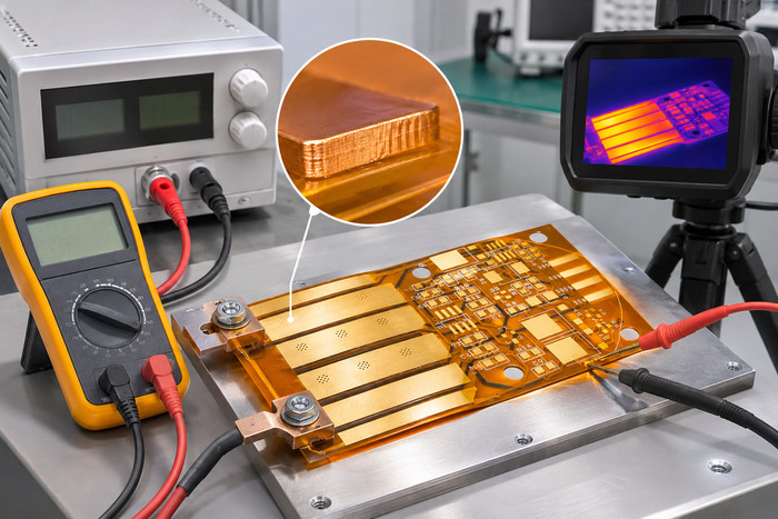
However, copper resistance increases with temperature. The result does not establish a verified continuous 10 A rating or prove that the circuit meets the voltage-drop target at its actual operating temperature. Final approval requires consideration of thermal conditions, connector resistance, the return path, and the complete installation environment.
Why Choose BestFPC for Custom High Current Flex PCB Manufacturing?
BestFPC combines fast delivery options, quality-controlled fabrication, and custom manufacturing capabilities to help customers reduce production defects, assembly problems, and unnecessary delays. Whether you need prototypes for an upcoming evaluation or are preparing an approved design for batch production, we provide manufacturing support tailored to your project requirements.
-
Fast prototyping to keep projects moving: BestFPC offers expedited manufacturing for eligible conventional FPC orders, including rapid prototype services and a 72-hour rush option for qualifying projects. Special heavy copper orders require individual confirmation based on materials, fabrication complexity, and available production capacity.
-
Consistent quality to reduce defective boards: Quality control covers incoming materials, fabrication, and finished-board inspection. AOI, bare-board electrical testing, and applicable dimensional and visual inspections help detect shorts, opens, fabrication defects, and deviations from approved drawings before shipment.
-
Custom heavy copper manufacturing for demanding applications: We evaluate suitable copper weights, polyimide materials, and fabrication structures to manufacture power interconnections according to your approved electrical and mechanical specifications.
-
Free DFM check to avoid costly rework: Manufacturing feasibility reviews help identify potential problems with heavy copper trace spacing, coverlay openings, connector thickness, and reinforcement features before production begins.
-
Prototype-to-production support for consistent specifications: Approved manufacturing files, material requirements, and acceptance criteria provide a common reference for prototype and subsequent batch orders, reducing the risk of specification mismatches.
BestFPC has extensive experience in flexible PCB fabrication and provides quality management documentation, including applicable ISO 9001 and ISO 13485 certification information, for customer review. Project-specific inspection requirements and acceptance criteria can be confirmed before an order is placed.
Frequently Asked Questions About High Current Flex PCBs
Q1: Can I request a manufacturing feasibility review before my Gerber files are complete?
A1: Yes. You can provide preliminary mechanical drawings, expected copper thickness, layer count, board dimensions, and major requirements for an initial discussion. Complete, approved fabrication files are required before production.
Q2: Can I order bare high current flex PCBs without component assembly?
A2: Yes. BestFPC provides custom bare flexible PCB manufacturing. Customers can arrange electronic component assembly and final equipment integration separately.
Q3: Can I specify a particular polyimide material brand and grade?
A3: Yes. Customers can submit preferred material brands, grades, and technical specifications for review. Final material selection depends on availability and compatibility with the required construction.
Q4: What happens if I modify the Gerber files after prototype approval?
A4: Submit the updated fabrication files with a clear revision description. Changes affecting copper patterns, holes, board outlines, or materials require confirmation of the revised manufacturing specifications.
Q5: Can BestFPC manufacture flexible PCBs according to customer-defined acceptance standards?
A5: Customers can specify applicable inspection and acceptance requirements before ordering, including relevant IPC-A-600 acceptance criteria. The applicable class, inspection scope, and any special requirements should be agreed upon before production.
Q6: Is special packaging available for irregularly shaped flexible PCBs?
A6: Special packaging requirements can be discussed during quotation. Suitable support, separation, and protective packaging can be arranged according to the board geometry and transportation requirements.
Q7: Can customers request an NDA before submitting confidential design files?
A7: Yes. Customers can discuss confidentiality requirements with BestFPC and confirm the applicable NDA arrangements before submitting proprietary design documents.
Q8: Can overseas customers request split deliveries or specify shipping destinations?
A8: Yes. Customers can provide their delivery country, shipping address, total quantity, and preferred delivery schedule during the RFQ process. The available arrangements are confirmed for each order.
Are overheating traces, excessive voltage drop, or difficult-to-manufacture heavy copper structures delaying your high current flex PCB project? BestFPC can help assess the manufacturing feasibility of your copper thickness, trace geometry, stackup, and connection features. Our custom fabrication services and quality controls help reduce manufacturing defects, connector-fit problems, and avoidable rework.
Looking for a reliable high current flex PCB manufacturer with fast delivery options and consistent quality? Send your Gerber files, operating current, copper requirements, order quantity, and target delivery date to sales@bestfpc.com. BestFPC provides custom high current flex PCB manufacturing, rapid prototyping, batch production, and a free DFM check to help move your approved design into production with fewer manufacturing complications.


.png)
.png)
.png)
.png)

.png)