


 2025-11-28
 BEST
BEST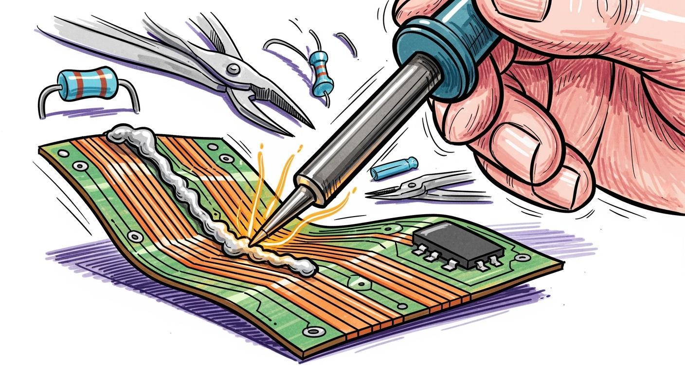
You want strong, reliable connections when working with thick copper soldering flexible pcb. Temperature control matters. Flux usage helps you avoid weak joints. If you ignore heat management, you risk damaging the flexible substrate. Specialized techniques protect your board and improve results. > Use best practices and proven steps to create durable, high-power connections every time.
Key Takeaways
- Control heat carefully to avoid damaging flexible substrates. Set your soldering iron between 330°C and 400°C for optimal results.
- Use a compatible flux pen to clean copper surfaces. This improves solder flow and prevents oxidation, ensuring strong connections.
- Pre-tin copper pads before soldering. This step creates a protective barrier against oxidation and enhances bond strength.
- Inspect solder joints for quality. Look for smooth, shiny surfaces to confirm reliable connections and prevent future failures.
- Store flexible PCBs flat and handle them with care. This practice maintains circuit integrity and prevents damage during assembly.
Challenges in Thick Copper Soldering Flexible PCB
Heat Control and Substrate Protection
You face significant risks when you apply too much heat during thick copper soldering flexible pcb projects. Polyimide substrates can handle high temperatures, but excessive heat can still cause delamination, weaken solder joints, and degrade the material. You must use precise thermal management to avoid these issues. Set your soldering iron between 330°C and 400°C. Use a flux pen to help the solder flow quickly and reduce the time heat stays on the board.
Tip: Always follow guidelines for thermal management to protect your flexible substrate and ensure long-term reliability.
- Overheating can lead to:
- Delamination of the polyimide substrate
- Weakened solder joints
- Material degradation and reduced performance
Solderability of Thick Copper Circuit Layers
Thick copper layers bring unique challenges. You need a solder mask at least 0.8 mils thick to protect copper traces from moisture and chemicals. If the mask is too thick, you risk reducing pad gaps, which can cause soldering defects. Uneven copper thickness can also cause warping during lamination, lowering your yield rates.
Follow guidelines for solder mask thickness and copper uniformity to improve solderability and reduce production issues.
| Challenge Description | Implication |
|---|---|
| Difficulty in solder mask adhesion due to high copper thickness | Insufficient coverage and registration accuracy, affecting PCB quality and reliability. |
| Stress on solder mask leading to cracking and peeling | Poor solder joint quality and reduced reliability during thermal cycling. |
| Challenges in exposure and development of thick solder mask | Potential undercut problems if exposure energy is inadequate. |
Mechanical Stress and Pad Bending
Mechanical stress can damage your pads and traces. Thermal expansion mismatches, installation stress, and heavy components all create pressure on the copper-dielectric bond. If you use an overpowered soldering iron or apply too much pressure, you risk thermal shock and pad bending. Aggressive reflow profiles can also weaken the dielectric layer.
- Common mechanical stress factors:
- Thermal expansion mismatches during soldering
- Over-tightening screws during installation
- Heavy components causing leverage on pads
- Excessive or repeated rework
- Incorrect soldering iron use
You must use careful thermal management and proper handling to prevent these issues. Always design your flex circuits with smooth bends and avoid sharp kinks to reduce stress concentrators.
Preparation for High-Power PCB Soldering
Selecting Solder and Flux Pen
You need to choose the right solder and flux pen for thick copper soldering flexible pcb projects. Low-temperature solder paste works best because it reduces the risk of overheating your flexible substrate. Avoid using too much solder. Excess solder can cause bridging and make inspection difficult. You want clean, reliable joints every time.
The right flux pen makes a big difference. It cleans and etches oxides from the copper surface. This improves solder flow and prevents copper oxidation after heating. The flux pen also reduces tension on the welded surface, so molten solder spreads and penetrates easily. You should always select a flux that matches your solder type and PCB materials. This ensures strong bonds and prevents oxidation.
| Best Practice | Description |
|---|---|
| Select Compatible Flux | Choose a flux that enhances the soldering process by preventing oxidation and improving solder flow. Ensure compatibility with solder type and PCB materials. |
| Use a Flux Pen | A flux pen helps clean and etch oxides on the surface of the flex PCB, improving solder flow and preventing copper oxidation after heating. It also reduces tension on the welded surface, allowing molten solder to spread and penetrate easily. |
Tip: Always check the specifications of your solder and flux pen before starting. This step prevents costly mistakes and improves your results.
Setting Soldering Temperature
You must set your soldering iron to the correct temperature. Thick copper circuit layers absorb heat quickly, so you need a higher temperature than standard PCBs. Set your soldering iron between 330°C and 400°C. This range allows the solder to melt and flow without damaging the flexible substrate. If you use a temperature that is too low, the solder will not bond properly. If you use a temperature that is too high, you risk delamination and substrate damage.
- Recommended temperature range: 330°C to 400°C
- Use a temperature-controlled soldering station for best results
- Monitor the heat closely during soldering
Note: Always preheat your soldering iron and test on a scrap piece before working on your actual PCB.
Surface Cleaning and Pre-Tinning
You must clean the surface of your thick copper circuit layers before soldering. Dust, oil, and oxidation can block solder flow and weaken joints. Use isopropyl alcohol and a lint-free cloth to wipe the copper pads. After cleaning, you should pre-tin the copper pads. Pre-tinning means applying a thin layer of solder to the pads before assembly. This step creates a protective barrier against oxidation and ensures a strong bond during soldering.
- Pre-tinning provides a protective barrier against oxidation, which is crucial for maintaining the integrity of thick copper layers on flexible PCBs.
- The solder coating from pre-tinning ensures a strong bond during assembly, enhancing the reliability of solder joints.
Callout: Clean and pre-tin every pad before you start. This step saves time and prevents rework later.
You want every connection to be strong and reliable. Careful preparation sets the foundation for successful thick copper soldering flexible pcb work.
Soldering Process for Thick Copper Circuit Layers
Applying Solder Paste and Flux
You want every circuit connection to last. Start by applying solder paste with precision. Use stencil printing for accurate placement on each circuit pad. Dispensing works well for direct application, especially on complex circuit layouts. Always use a small amount of solder paste. Too much paste can cause bridging and lead to circuit defects. Select a flux that matches your solder alloy and the requirements of your assembly process. The right flux ensures compatibility and clean results.
Tip: Choose a flux that leaves minimal residue and matches your circuit materials. This step prevents future cleaning challenges.
Flux plays a vital role in creating strong solder joints. It removes oxides from the metal surface, exposes clean copper, and prevents new oxidation during heating. Flux also lowers the surface tension of molten solder, helping it spread and penetrate the base metals of your circuit. This action increases the mechanical strength and conductivity of your joints. Proper flux use minimizes defects like bridging and cracks, boosting your soldering pass rates.
| Effect of Flux | Description |
|---|---|
| Remove Metal Surface Oxides | Flux ingredients dissolve metal oxides, exposing clean metal for proper solder wetting, preventing poor adhesion. |
| Prevent Secondary Oxidation | Flux forms a protective film at high temperatures, maintaining clean metal surfaces and inhibiting new oxide formation. |
| Reduce Solder Surface Tension | Surfactants in flux lower solder surface tension, allowing better spreading and penetration of solder into base metals. |
| Enhance Mechanical Strength and Conductivity | Flux improves wetting, leading to strong intermetallic compounds, increasing joint strength and reducing electrical resistance. |
| Minimize Welding Defects | Proper flux use prevents defects like bridging and cracks, improving soldering pass rates significantly. |
You can also pot the joints with epoxy after soldering. This step adds structural integrity to your circuit, but you must avoid mechanical stress that could cause failure.
Hand Soldering and Hot Bar Techniques
You have two main options for thick copper soldering flexible pcb: hand soldering and hot bar soldering. Hand soldering gives you control over each circuit joint. Use a temperature-controlled iron and work on a clean, flat surface. Stabilize your circuit with clamps to prevent movement. Always check that the soldering pads remain flat and free from bending. This practice prevents stress on your flexible circuit.
Hot bar reflow soldering works well for thick copper circuit layers. This method uses a heated bar to apply both heat and pressure to the circuit. You can choose from air, servo, or manual pedal systems to control pressure. Select a solder alloy that fits your needs, such as tin-lead or lead-free SAC305. For best results, design your circuit with trace widths at least 50% of the pitch. Equal trace sizes help distribute heat evenly across the circuit.
| Equipment Type | Description |
|---|---|
| Hot-Bar Reflow Soldering | Effective for soldering thick copper layers on flexible PCBs. |
| Pressure Application | Options include AIR, SERVO, and MANUAL PEDAL for applying pressure. |
| Solder Alloys | Common alloys include tin-lead and lead-free options like SAC305. |
| Design Considerations | PCB trace width should be 50% of pitch; equal trace sizes improve heating. |
Note: Always stabilize your circuit during soldering to avoid pad bending and ensure reliable joints.
Managing Heat and Pressure
You must manage heat and pressure carefully to protect your circuit. Start by baking your circuit before soldering. For single and double-sided circuits, bake for 2 to 3 hours at 105 to 115°C. Three-layer polyimide circuits need 3 to 4 hours. For four layers or more, bake at least 4 hours. Rigid-flex circuits require longer baking times as thickness increases.
Control your reflow profile to prevent thermal shock. Ramp up the temperature slowly, about 1–2°C per second. Keep the peak temperature below 260°C for polyimide-based circuits. This approach prevents delamination and protects the resin in your circuit.
Avoid shock heating. Ramp temperature gradually and stay within resin limits. Avoid sharp thermal transitions in reflow soldering. Rapid heating or cooling causes materials to expand or contract at different rates. If the resin can’t keep up, it will delaminate.
Always use a temperature-controlled soldering station. Monitor the heat closely and adjust as needed. Apply pressure evenly during hot bar soldering. Do not use excessive force, as this can damage the circuit and cause pad lifting.
Component and Stiffener Handling
Handle every component and stiffener with care to protect your circuit. Work in a cleanroom environment and wear ESD-safe gloves. Store your flexible circuits flat in antistatic bags at controlled temperature and humidity. Avoid bending the circuit before assembly. Flat storage prevents weakening of the substrate and maintains circuit integrity.
Use precise thermal profiles during soldering to avoid damaging components. For surface-mount technology, keep the peak temperature between 245–260°C for no more than 10 seconds. Low-temperature solder alloys reduce the risk of damage to your circuit. Use custom fixtures or jigs to hold the circuit flat during soldering. These tools prevent excessive pressure and keep your circuit stable.
- Use cleanroom protocols to avoid contamination.
- Store circuits flat in antistatic bags.
- Minimize bending before assembly.
- Solder with controlled thermal profiles.
- Use low-temperature solder alloys.
- Employ custom fixtures for stability.
Callout: Careful handling and precise soldering protect your circuit investment and ensure long-term reliability.
You can achieve strong, reliable solder joints on thick copper circuit layers by following these steps. Every action you take improves the durability and performance of your circuit. Apply these techniques to every project and see the difference in your results.
Post-Soldering Care and Inspection
Cleaning Residues
You want every high-current pcb to perform at its best. After soldering, cleaning flux residues is essential. Residues can cause corrosion, electrical leakage, and reliability issues. You should use low-residue or no-clean flux materials to minimize residue formation. Always follow optimized reflow profiles and recommended temperature settings to activate flux completely. For effective cleaning, select high-purity Isopropyl Alcohol (IPA) and use a brush or cotton swab to dissolve flux residues. Water washing with pure or deionized water offers a simple and cost-effective method. Solvent cleaning works quickly for stubborn residues. Regular cleanliness inspections and performance testing help you verify cleaning effectiveness.
| Solvent | Effectiveness | Safety Level |
|---|---|---|
| Isopropyl Alcohol (IPA) | Best for removing post-soldering residues | Relatively safe with proper ventilation |
| Acetone | Effective for tough residues | Riskier, not generally recommended for PCBs |
Tip: Brush the circuit board with IPA or soak it in a suitable solvent for thorough cleaning. Clean boards last longer and deliver better performance.
Checking Connection Reliability
You need to confirm that every joint on your high-current pcb is solid. Reliable connections prevent failures and keep your circuits running smoothly. Start by inspecting solder joints for a smooth, shiny surface with a concave fillet. Dull, grainy, or cracked joints signal problems. Gently wiggle each component; if it moves or feels loose, the joint may be weak. Use a multimeter to check for continuity. Resistance above 1 ohm often indicates a faulty joint.
| Inspection Method | Key Benefits |
|---|---|
| Automated Optical Inspection (AOI) | Fast, non-destructive, accurate for surface defects |
| X-Ray Inspection | Non-destructive, detects hidden/internal defects, essential for complex boards |
| Solder Paste Inspection (SPI) | Prevents defects, precise 3D measurement, reduces rework |
Callout: Reliable inspection ensures your high-current pcb meets performance standards and avoids costly failures.
Troubleshooting Common Issues
You may encounter cold solder joints, solder bridging, or pad lifting during thick copper soldering flexible pcb work. Identify cold solder joints by checking for insufficient melting or bonding. Control heat precisely with a soldering iron set between 260°C and 300°C. Avoid overheating to prevent substrate damage. Heat the joint, apply fresh solder, and keep it stable while cooling. For solder bridging, use a narrow tip solder iron and wet it with solder paste. Heat the bridge and gently drag out the melted solder. Test with a multimeter to ensure pads are no longer shorted.
| Strategy | Description |
|---|---|
| Increased Land Spacing | Wider gaps impede capillary flow between pins. |
| Rounded Pad Corners | Discourage corner wetting initiation points. |
| Lower Peak Temperature | Reduces alloy fluidity. |
| Improved Cooling Ramp | Faster setup increases viscosity quicker before bridges solidify. |
Note: Quick troubleshooting keeps your high-current pcb reliable and ready for demanding applications.
You can achieve reliable results with thick copper soldering on flex pcbs by following proven steps. Control heat during assembly, use high thermal conductivity materials, and avoid stacking copper busbars. Clean every joint and use SMT stencils for precise solder paste application. Never bend flex pcbs while soldering. Clean off all flux residues to prevent corrosion. Test your high-power pcb with dynamic flex and thermal cycling for long-term reliability. Thicker copper busbars boost current-carrying capacity and lower resistance, making heavy-copper pcbs and rigid-flex pcbs ideal for demanding environments. For best results, follow this checklist:
- Set the correct temperature for high thermal conductivity.
- Apply compatible flux and clean copper busbars.
- Inspect every high-power pcb connection.
- Store flex pcbs and copper busbars flat.
- Use industry standards like UL 796F and IPC 6013.
You can trust these techniques to deliver high-power pcb performance. If you want expert support or have questions about flex pcbs, copper busbars, or rigid-flex pcbs, send us your inquiry through our contact form or email. Your next project deserves the best.
.png)
.png)
.png)
.png)

.png)

