


 2025-11-27
 BEST
BEST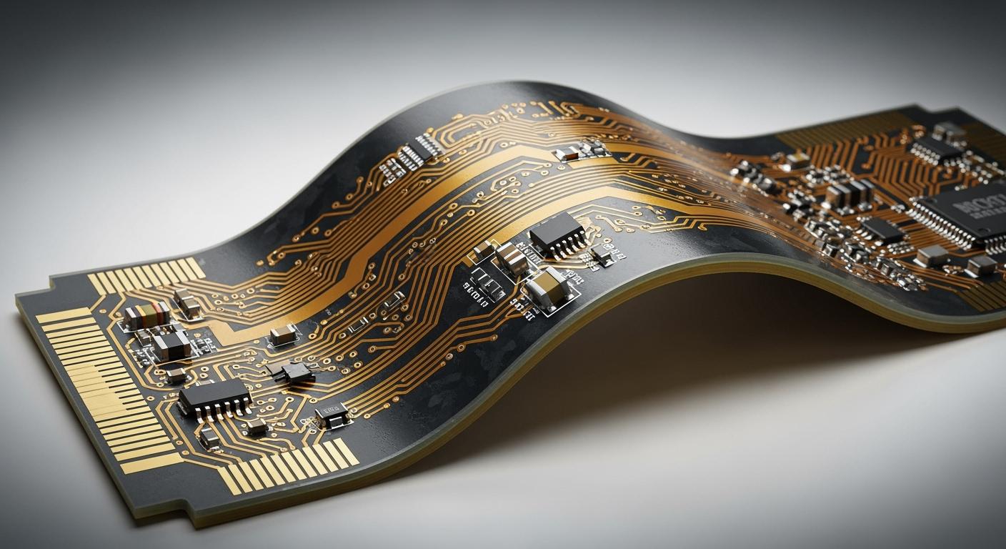
You can add rigid layers to a flex PCB by integrating solid board sections into flexible circuits. This process increases mechanical strength and shields sensitive areas from bending. When you reinforce critical zones, you prevent cracks and extend the life of your electronic assemblies.
Tip: Rigid sections support connectors and components, reducing stress on flexible parts.
Key Takeaways
- Adding rigid layers to flex PCBs increases mechanical strength and protects sensitive areas from bending.
- Use FR-4 for rigid areas and polyimide for flexible sections to ensure durability and flexibility in your design.
- Design smooth transitions between rigid and flexible zones to reduce stress and prevent cracks.
- Communicate clearly with your manufacturer about your design to avoid costly mistakes and ensure quality.
- Consider rigid-flex designs for improved reliability, simplified assembly, and reduced risk of signal loss.
Rigid-flex PCB basics
Structure and definition
Rigid-flex PCBs combine the benefits of both rigid and flexible circuit boards. You use these hybrid boards when you need durability and flexibility in one design. The rigid sections provide a stable base for mounting components. The flexible sections allow the board to bend and fit into tight spaces. This structure helps you create compact and reliable electronic devices.
You often see rigid-flex PCBs in medical devices, aerospace systems, and consumer electronics. These boards reduce the need for connectors and cables, which can fail over time. By using fewer interconnections, you improve signal integrity and lower the risk of mechanical failure.
Note: Rigid-flex PCBs can handle repeated bending in specific areas while protecting sensitive parts from stress.
Integration of rigid and flex layers
When you design a rigid-flex PCB, you integrate flexible circuits with one or more rigid boards. You can position the rigid sections on the outside or inside, depending on your application. The flexible layers run through the rigid areas, creating a continuous electrical path. This method allows you to add rigid layers where you need extra support, such as under connectors or heavy components.
The typical stackup includes several layers of flexible polyimide and rigid FR-4 material. You bond these layers together during manufacturing. The flexible layers remain unbonded in the bendable regions, so they can move freely. In the rigid areas, all layers are laminated to form a solid structure.
- Key integration methods:
- Attach flexible layers to rigid sections during lamination.
- Use continuous flex layers through rigid zones for uninterrupted signals.
- Select materials that match your mechanical and electrical needs.
You can add rigid layers to improve durability and extend the life of your PCB. This approach gives you the freedom to design complex shapes without sacrificing strength.
How to add rigid layers
Design stackup and materials
You start by planning your rigid-flex PCB in design software. Most tools let you define rigid and flexible zones, so you can visualize the final product. You select the stackup, which is the arrangement of layers in your board. The stackup determines how you add rigid layers and where you place flexible sections.
Choose materials that match your application. For rigid areas, FR-4 is common because it provides strength and stability. For flexible regions, polyimide works well due to its bendability and heat resistance. You must ensure that the flexible layers run continuously through the rigid sections. This design keeps your signals uninterrupted and improves reliability.
Tip: Use a table to compare material properties before you finalize your stackup.
| Material | Rigid Area | Flex Area | Key Benefit |
|---|---|---|---|
| FR-4 | Yes | No | Mechanical support |
| Polyimide | No | Yes | Flexibility |
| Adhesives | Yes | Yes | Layer bonding |
You export Gerber files from your design software. These files guide the manufacturer during production. Double-check your stackup and layer assignments before you send your files.
Flex-to-rigid transitions
You need to pay special attention to the transition zones between rigid and flexible areas. These regions often experience mechanical stress. If you design smooth transitions, you reduce the risk of cracks and delamination.
Avoid sharp corners where the flex meets the rigid section. Rounded edges distribute stress more evenly. You can add rigid layers under connectors or heavy components to prevent damage. Make sure the flexible layers remain continuous through these transitions.
Note: Reinforce transition zones with extra coverlay or stiffeners if your application requires frequent bending.
Manufacturing steps
Manufacturing a rigid-flex PCB involves several precise steps. You begin with lamination, where you bond the rigid and flexible layers together. The manufacturer uses heat and pressure to create a solid structure in the rigid zones while leaving the flexible areas unbonded.
Next, you drill holes for vias and component leads. The process must not damage the flexible layers. After drilling, you plate the holes with copper to ensure electrical connectivity. Routing shapes the board and separates the rigid and flexible sections.
- Key manufacturing steps:
- Laminate rigid and flexible layers.
- Drill and plate vias.
- Route the board outline.
- Apply coverlay to protect flexible regions.
You must communicate your design intent clearly to the manufacturer. Provide detailed drawings and notes about where you want to add rigid layers and how you expect the board to bend.
Quality control
Quality control ensures your rigid-flex PCB meets reliability standards. You test the board for electrical continuity and inspect for defects like cracks or delamination. Manufacturers use automated optical inspection (AOI) to check layer alignment and solder mask coverage.
You should request mechanical testing for boards that will bend repeatedly. Flex-to-rigid transitions need extra scrutiny. If you find any weak points, you can adjust your design or material choices before mass production.
Alert: Always verify that the flexible layers remain continuous through the rigid sections. This step is critical for signal integrity and long-term durability.
You improve your product’s lifespan and performance when you add rigid layers with careful design, manufacturing, and quality control.
Benefits and challenges
Durability and support
When you add rigid layers to your flex PCB, you increase the board’s mechanical strength. Rigid sections protect sensitive components from bending and vibration. You can mount connectors and heavy parts on these areas without worrying about cracks or damage. The rigid zones act as shields, absorbing stress and extending the lifespan of your device. You also reduce the risk of signal loss because the board maintains its shape under pressure.
Tip: Place rigid layers under connectors to prevent solder joint failures during repeated use.
Assembly advantages
Rigid-flex PCBs simplify your assembly process. You can fold or shape the board to fit tight spaces, which reduces the need for extra cables or connectors. This design lowers the number of assembly steps and minimizes errors. You save time and money because you handle fewer parts. The rigid sections provide stable mounting points, making soldering and inspection easier.
- Benefits during assembly:
- Fewer interconnections
- Faster installation
- Improved reliability
You also streamline testing since the board combines flexible and rigid areas in one unit.
Common issues and solutions
You may face challenges when you add rigid layers to a flex PCB. Stress often builds up at the junctions between rigid and flexible zones. This can lead to delamination or cracks if you do not design smooth transitions. Cost is another concern because rigid-flex boards require specialized manufacturing.
| Issue | Solution |
|---|---|
| Stress at junctions | Use rounded corners, add coverlay |
| Delamination | Select quality adhesives |
| High cost | Optimize design, reduce layers |
Alert: Always communicate your design intent with your manufacturer. Clear instructions help avoid costly mistakes and ensure your board meets durability standards.
You can overcome most challenges by planning your stackup, choosing the right materials, and working closely with your fabrication partner.
You can boost your PCB’s durability by adding rigid layers to key areas. Start with careful stackup planning, select the right materials, and design smooth flex-to-rigid transitions. Rigid-flex designs give you strength and flexibility in one board. Consider this approach for your next project to improve reliability and simplify assembly. If you have questions or want expert advice, send us an inquiry or use our contact form. Invest in quality now and build electronics that last.
.png)
.png)
.png)
.png)

.png)

