


 2026-10-26

 BEST
Limited enclosure space often means mounting circuit sections in different positions while keeping power and signal connections organized. A 4 Layer Rigid Flex PCB brings those sections together, but successful manufacturing requires the rigid thickness, flexible connection, copper construction, and assembly support to work as one structure.
BestFPC is a China-based 4 layer rigid flex PCB manufacturer serving US and global customers with custom fabrication, engineering support, and coordinated assembly. Our engineering team reviews stackups and transition areas, while our fabrication and assembly teams coordinate board production, component sourcing, and SMT assembly. This gives buyers one manufacturing partner for both PCB and PCBA requirements. Send your drawings to sales@bestpcbs.com for an engineering review and quotation.
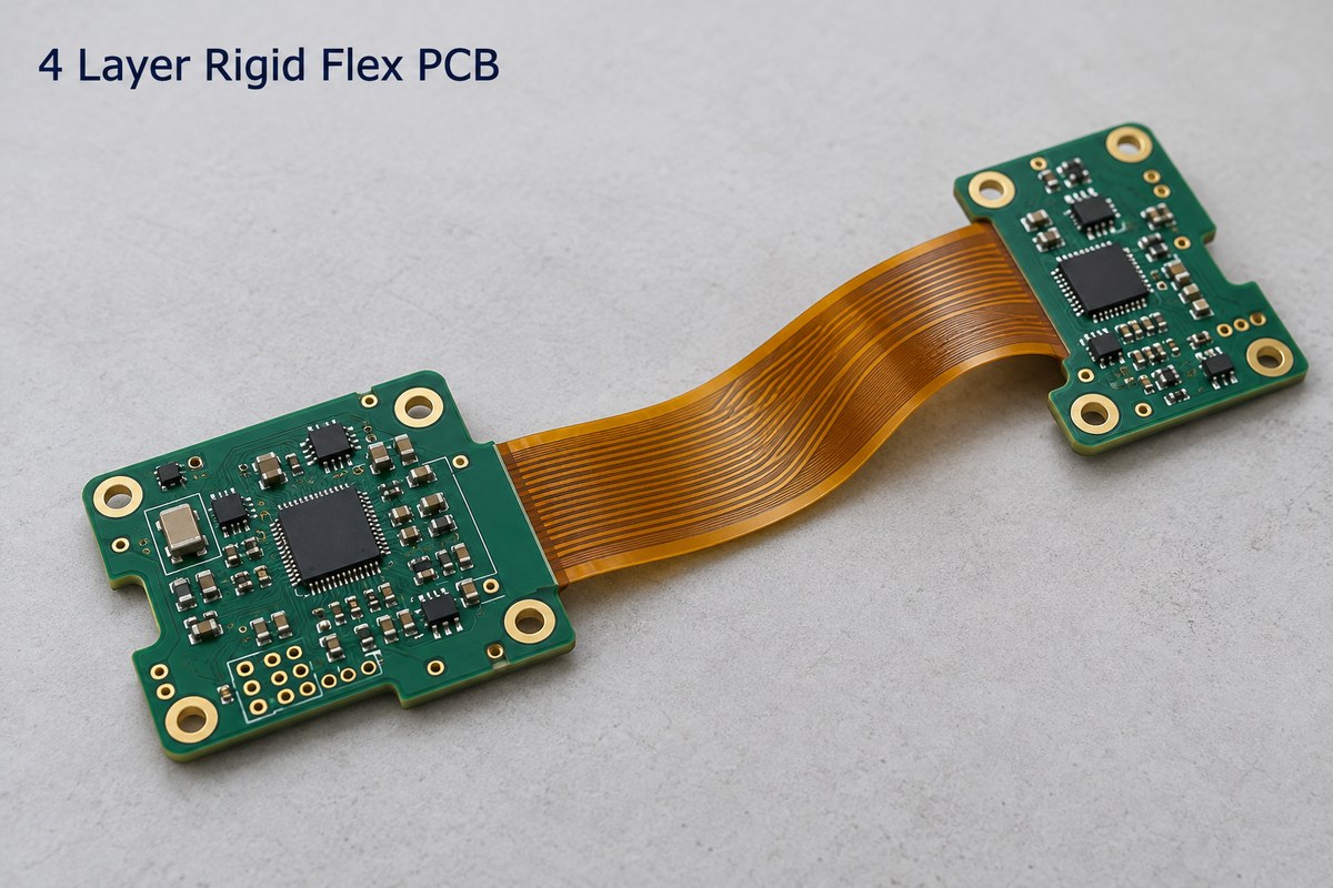
4 Layer Rigid-Flex PCB Manufacturing Capabilities
BestFPC provides custom four-layer rigid-flex fabrication using FR-4 rigid sections and polyimide flexible regions. Separate control of rigid and flex thicknesses supports stable component mounting and flexible interconnections within the same board.
| Manufacturing Parameter | Capability / Condition |
|---|---|
| Construction | Four conductive layers in the rigid region; flex-region layer count follows the approved stackup |
| Finished board thickness | 0.3–3.0 mm; specify rigid and flex thicknesses separately |
| Board thickness tolerance | Above 1.0 mm: ±10%; at or below 1.0 mm: ±0.1 mm |
| Adhesiveless PI options | 0.5, 1, 2, or 3 mil; laminate combination subject to review |
| Inner-layer line / space | 3 / 3 mil at 18 μm finished copper; 4 / 4 mil at 35 μm |
| Outer rigid-layer line / space | 3.5 / 3.5 mil at 18 μm finished copper; 4 / 4 mil at 35 μm |
| Controlled impedance tolerance | ±10%, subject to the agreed stackup and test requirements |
These capabilities give engineers practical starting points for routing, material selection, and mechanical fit. Line and space values are before manufacturing compensation; the engineering review checks the selected combination of copper, thickness, and geometry together. Flex thickness and tighter product-specific tolerances receive separate review.
The flex-region layer count follows the connection and bending requirements rather than automatically matching all four rigid-region layers. BestFPC reviews where each layer continues or terminates so the finished construction supports the intended installation.
How Does BestFPC Review a 4 Layer Rigid Flex Stackup?
BestFPC’s engineers review the stackup against fabrication and mechanical files to identify construction conflicts before production. The review connects electrical requirements with the way the board will be manufactured and installed.
- Layer construction review: The team checks conductive layers, dielectric materials, copper weights, and regional thicknesses together, helping resolve mismatches between the drawing and the proposed material buildup.
- Installation geometry review: Engineers examine bend locations, direction, mounting points, and enclosure clearance to identify interference and distinguish static installation needs from repeated movement.
- Rigid-to-flex transition review: The review covers rigid edges, coverlay termination, conductor clearance, and adhesive or reinforcement areas, helping keep the intended bend zone free from unwanted constraints.
- Impedance and material review: The team checks impedance requirements against reference planes, dielectric construction, target values, and tolerances so material selection and testing support the same electrical specification.
When a manufacturing conflict appears, BestFPC explains the issue and proposes an adjustment for customer approval. Buyers receive a clearer production specification before committing to tooling and fabrication.
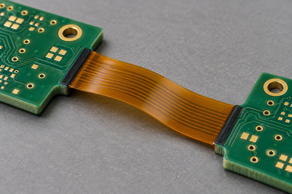
4 Layer Rigid-Flex PCB Assembly from Prototype to Production
BestFPC coordinates rigid-flex fabrication, component sourcing, and assembly for prototypes, low-volume orders, and production. Full turnkey, partial turnkey, and consigned-component options let customers choose how much of the purchasing and assembly work to place with one supplier.
| Assembly Parameter | Available Scope |
|---|---|
| Minimum package | 0201 |
| Maximum component dimensions | 45 × 45 mm |
| Placement height | Up to 15 mm |
| Assembly processes | SMT and mixed SMT / through-hole |
| Component supply | Full turnkey, partial turnkey, or consigned |
- Board support during assembly: Assembly planning addresses panel support, fixture needs, and flex-tail handling so the rigid mounting areas remain stable during printing and placement. Component clearance and access are reviewed against the actual layout.
- Fabrication-to-SMT coordination: Board delivery format, panel handling, BOM, and placement data are aligned before assembly, reducing handoffs between separate PCB and SMT suppliers.
- Prototype-to-production continuity: The approved board revision and assembly requirements provide a common baseline for pilot and repeat orders. Findings from the first build can be incorporated before quantities increase.
For buyers, this means coordinating bare boards, components, and assembly through one manufacturing partner, with a clearer division of supply responsibilities.
How Does BestFPC Control Rigid-Flex PCB Quality?
BestFPC combines bare-board inspection with assembly-stage checks to address both circuit integrity and populated-board quality. The inspection scope follows the product’s acceptance requirements, keeping PCB and PCBA checks distinct.
Quality Control for Bare Boards and Assembled PCBs
- Bare PCB Inspection: BestFPC checks electrical continuity and isolation, board dimensions, surface finish, and specified copper requirements. Cross-section inspection and impedance testing can be included in the approved quality plan to assess internal construction and controlled-impedance features.
- PCBA Inspection and Testing: First-article inspection, SPI, AOI, X-ray, ICT, and functional testing are available as applicable to the build. These methods address solder-paste deposition, component placement, solder joints, and electrical performance at the relevant stages. Functional testing uses project-specific procedures, fixtures, and acceptance limits.
Quality documentation is matched to the order and can include conformity records, electrical test results, microsection reports, solderability results, and copper-thickness reports. These records support incoming acceptance and provide a reference for managing repeat orders.
What Determines the Cost of a 4 Layer Rigid Flex PCB?
The cost of a four-layer rigid-flex PCB is driven by its construction, panel utilization, quantity, and test scope. BestFPC reviews these factors together to identify practical cost options while preserving the design’s required function.
- Outline and panel utilization: Long flex tails and irregular shapes affect material use. BestFPC evaluates the production layout and panel restrictions to identify opportunities to improve utilization without changing essential mounting or connection features.
- Materials and process complexity: Specialized laminates, additional lamination steps, tight tolerances, and complex via structures increase manufacturing work. Engineering review helps distinguish necessary requirements from features that add cost without supporting the application.
- Prototype, pilot, and production quantities: Setup and tooling costs have a greater effect on small orders. Quantity-based quotations help buyers compare development costs with repeat-production pricing using the same design revision.
- Assembly and inspection scope: Component sourcing, assembly preparation, fixtures, and test requirements contribute to the total. A coordinated PCB and PCBA quotation makes these costs easier to assess together.
For US orders, the comparison also includes packaging, freight, and applicable import charges. Delivery planning separates manufacturing and assembly time from transit, giving buyers a more useful basis for evaluating total cost and arrival dates. Material or layout changes are implemented after customer approval.
4 Layer Rigid Flex PCB Manufacturing Case Study for a USA Customer
This USA customer case study centers on a compact power-distribution and control module for industrial automation equipment. Its manufacturing requirements bring together rigid mounting sections, a thin flexible connection, and controlled copper construction within a restricted enclosure.
Customer Application
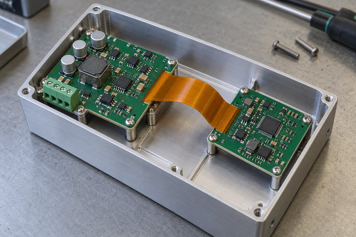
The rigid regions carry power-management components, control circuitry, and connectors. The flexible section connects these regions around the enclosure geometry, allowing the mounting areas to sit in different positions rather than forcing every circuit onto one plane.
Four conductive layers provide routing space for power, return paths, and control signals. The integrated flex connection replaces the need for a separate cable assembly between the connected board sections and supports a static installation layout.
Customer Requirements
The board combines a 2.0 ± 0.2 mm rigid region with a 0.25 ± 0.03 mm flex region. The construction must accommodate the mounting interfaces while preserving the flexible connection path, with the following material, copper, finish, and flatness requirements.
| Product Parameter | Specification |
|---|---|
| Layer count | 4 |
| Rigid-region materials | FR-4 Tg 180 and polyimide |
| Rigid-region thickness | 2.0 ± 0.2 mm |
| Flex-region thickness | 0.25 ± 0.03 mm |
| L2 / L3 copper | 1 oz |
| L1 / L4 copper | ½ oz base copper + 20 μm plating |
| ENIG finish | Au: 2.0 μin; Ni: 120–200 μin |
| Warpage requirement | Less than 0.75% |
| Transition treatment | Black adhesive at the rigid-flex junction |
Manufacturing Challenges
- Regional thickness control: The rigid section must seat correctly at its mounting interfaces, while the flex section must fit the installation path. Each region needs its own thickness control to avoid mechanical interference.
- FR-4 / PI bonding and transition geometry: Lamination must bond the materials while preserving the free-flex area. Resin flow, coverlay termination, and the adhesive boundary influence where the board can bend.
- Copper construction and registration: The 1 oz inner layers and plated outer layers require coordinated imaging, etching, and plating allowances. Layer alignment must preserve the intended conductor geometry and interconnections.
- Warpage and assembly fit: The less-than-0.75% requirement supports board seating and assembly handling. Copper distribution, lamination, and panel support all contribute to controlling flatness.
BestFPC’s Manufacturing Solution
BestFPC’s 4 layer rigid flex PCB solution addresses these requirements through coordinated stackup preparation, rigid-to-flex transition processing, and copper and thickness control:
- Regional material buildup: The production stackup combines FR-4 Tg 180, PI, bonding materials, and coverlay against the separate rigid and flex thickness targets. Copper buildup is included in the finished-thickness calculation.
- Controlled transition treatment: The rigid edge, coverlay termination, and black-adhesive boundary are coordinated with the installation geometry. This preserves the intended flex length while applying the specified junction treatment.
- Copper and flatness control: Imaging and etching allowances account for the copper construction, while outer-layer plating addresses the specified copper buildup. Copper balance and panel support are considered alongside dimensional and warpage checks.
- Fabrication and assembly coordination: DFM findings are resolved before production release, and the approved construction is carried through to panel handling, fixture support, component clearance, and installation access.
Customer Benefits
The integrated connection reduces separate board-to-board connectors and wiring, freeing space otherwise needed for cable routing and mating interfaces. Rigid mounting areas can follow the enclosure layout while the flexible section maintains the connection between them.
For the buyer, coordinated fabrication and assembly also reduce supplier handoffs. Questions about board thickness, mounting clearance, and assembly support can be addressed within one manufacturing discussion rather than passed between separate vendors.
When Should US Buyers Choose BestFPC Over a Local Rigid Flex PCB Manufacturer?
BestFPC is a strong RFQ candidate for US buyers seeking custom four-layer rigid-flex fabrication with engineering support and coordinated assembly. With our manufacturing facilities in China, we offer US buyers an alternative to local suppliers, combining custom fabrication, engineering support, and assembly services under one roof.
| Project Need | BestFPC Support |
|---|---|
| Custom rigid and flex construction | Regional thickness, copper, and material review |
| Manufacturing questions before release | Stackup, transition, and DFM support |
| PCB and PCBA from one partner | Fabrication, component sourcing, and assembly coordination |
| Prototype through repeat production | Shared design baseline across order stages |
| Defined acceptance requirements | Separate PCB and PCBA inspection planning |
| US delivery and budget planning | Quantity-based quotes and cross-border delivery coordination |
For engineering teams, the value is access to manufacturing input before the build. For purchasing teams, it is the ability to discuss fabrication, assembly, inspection, and delivery in one quotation process. This is particularly useful when replacing a fragmented supply chain or evaluating a second source for repeat orders.
BestFPC manufactures in China and serves US customers through cross-border supply. For projects that permit overseas production, an RFQ provides a concrete comparison of unit pricing, setup costs, inspection scope, and delivered cost—without assuming that geography alone determines value.
What Files Are Needed to Quote a Custom 4 Layer Rigid Flex PCB?
BestFPC reviews your fabrication and mechanical files to establish the manufacturing scope, identify open engineering questions, and prepare a project-specific 4 layer rigid-flex PCB quotation. A consistent file package helps the team respond with relevant technical feedback and pricing.
The quotation package includes:
- Fabrication files: Gerber data, drill files, outline drawing, layer identification, and stackup.
- Mechanical requirements: Rigid and flex thicknesses, tolerances, bend locations, installation geometry, and reinforcement or adhesive areas.
- Electrical and material requirements: Copper specifications, materials, surface finish, impedance targets, and permitted alternatives.
- Order and delivery details: Prototype or production quantities, quantity breaks, required arrival date, and US delivery address or postal code.
- Quality requirements: Acceptance criteria, electrical testing, required reports, and marking or packaging instructions.
- Assembly files, if needed: BOM, component placement file, assembly drawings, component supply arrangement, and programming or test requirements.
If the stackup or a material choice is still open, BestFPC can explain the manufacturing and cost implications of the available options. You can begin the discussion with the current design package and work with the team toward a production-ready specification.
FAQs about 4 Layer Rigid Flex PCB
Does a four-layer rigid-flex PCB have four flexible layers?
Not necessarily. The rigid region has four conductive layers, while the flexible region follows the approved stackup and may use fewer layers.
Can I supply components for assembly?
Yes. BestFPC supports consigned components as well as full and partial turnkey arrangements, allowing customers to retain control of selected parts or sourcing channels.
Can prototype findings be incorporated before a repeat order?
Yes. Approved changes can be incorporated into the controlled fabrication and assembly files before the next build, keeping production aligned with the updated design.
Is this construction suitable for continuous bending?
The power-module construction discussed here is intended for static installation. Repeated movement requires a separate review of flex thickness, copper, bend geometry, and expected movement.
Does every order include functional testing?
Functional testing is a project-specific service. BestFPC works with the required test procedure, fixture, and acceptance limits when it is included in the assembly scope.
Can I obtain an estimate before the stackup is finalized?
Yes. BestFPC can prepare a preliminary estimate with the construction assumptions identified, then finalize pricing once the stackup and manufacturing scope are settled.
At BestFPC, our DFM support helps identify stackup conflicts, rigid-to-flex transition issues, and assembly constraints before production, reducing the risk of avoidable revisions. Our ISO 9001 and ISO 13485 certifications demonstrate our commitment to quality management and consistent manufacturing processes, supporting customers' supplier qualification processes. Bring your four-layer rigid-flex project to BestFPC for coordinated engineering support, fabrication, and assembly. Send your drawings, quantities, and US delivery requirements to sales@bestpcbs.com to request a 4 layer rigid-flex PCB quotation tailored to your project.


.png)
.png)
.png)
.png)

.png)